Current Language
×
Japanese (Japan)

言語の選択:

トグル・メニュー
Current Language
×
Japanese (Japan)

言語の選択:

ダウンロード

マニュアル、データシート、ソフトウェアなどのダウンロード:

ダウンロード・タイプ
型名またはキーワード

フィードバック

4200A-SCSパラメータアナライザでのMOSFETのゲート電荷測定


はじめに

パワーMOSFETは、高速スイッチングデバイスを含む様々な用途で使用されている。デバイスのスイッチング速度は、内部容量によって影響を受け、通常その容量値は入力ゲートCgsおよびドレイン容量Cgdから導出されるCissおよびCossという項目でデータシートに記載される。それらの容量を特定することに加えて、ゲート電荷(QgsおよびQgd)でもMOSFETのスイッチング性能を評価することができ

MOSFETのゲート電荷を測定する1つの方法がJEDEC JESD24-2規格 「Gate Charge Test Method」に記載されている。この方法では、ゲート電流を与えた状態で、ゲート・ソース間電圧を時間の関数として測定し、ゲート電圧波形の結果からゲート-ソース電荷(Qgs)、ゲート-ドレイン電荷(Qgd)、およびゲート電荷(Qg)を導出する。

4200A-SCSパラメータアナライザの2つのソース・メジャー・ユニット(SMU:source measurement unit)と、システムに含まれるゲート電荷測定用テストライブラリを使用し、MOSFETのゲート電荷測定を行 う こ と が で き る。ま た、 こ の テ ス ト は、4200A-SCS Clarius+ Software Suiteで提供される多くのテストライブラリの1つである。本アプリケーション・ノートでは、4200A-SCSパラメータアナライザを用い、JEDECに準拠したゲート電荷測定に基づく、MOSFETのゲート電荷測定方法を解説する。

ゲート電荷測定の概要

ゲート電荷測定法は、一定のテスト電流(Ig)をMOSトランジスタのゲートに流し、ゲート-ソース電圧測定値(Vgs)とゲートに流入する電荷値に対してプロットする。ドレイン端子には一定の電圧バイアスを印加する。図1に、パワーMOSFETのゲート電圧対ゲート電荷を示す。

ゲート電荷(Q)は、印加したゲート電流および時間(Igdt)から導出される。ゲート-ソース電荷(Qgs)は、図1に示すように、電圧(Vgs)がほぼ一定である平坦領域の始まりに達するまでに必要な電荷である。平坦(またはミラー)電圧(Vpl)は、JEDEC規格に従い、dVgsが最小のときのゲート-ソース間電圧で定義される。トランジスタがオフ状態からオン状態にスイッチングしている時にその電圧が平坦となる。また、このスイッチングを完了するのに必要なゲート電荷、すなわち、デバイスを平坦領域の開始から終了に切り替えるのに必要な電荷は、ゲート-ドレイン電荷(gate-drain charge)(Qgd)として定義され、ミラー電荷として知られている。ゲート電荷(Qg)は、原点からゲートVgsが指定した最大値(Vgs)が指定した最大値(VgsMax)と等しくなるまでの電荷である。

 
パワーMOSFETの電圧対ゲート電荷を示すMOSFETゲート電荷測定グラフ
図1. 典型的なパワーMOSFETのゲート電圧対ゲート電荷
 

S1は、原点から最初の平坦点までの傾きで、S2は、最後の平坦点から指定した最大ゲート電圧(VgsMax)までの傾きである。それらの傾きは、JESD24-2規格に規定されるように、QgsおよびQgdを計算するために使用される。

図2に、典型的な時間に対するゲートおよびドレイン波形を示す。電流をゲートに与えると、Vgsは閾値電圧に達するまで増加する。このとき、ドレイン電流(Id)が流れ始める。時刻t1でCgsが充電されると、Idは一定となり、ドレイン電圧(Vd)は低下する。Vgsは、平坦領域の終わりまで一定のままである。Cgdが時間t2で充電されると、ゲート-ソース電圧(Vgs)は、指定された最大ゲート電圧(VgsMax)に達するまで再び増加し始める。
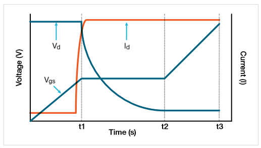
 
ゲートとドレインの波形を時間の関数として示すグラフ
図2. MOSFETの時間に対するVgs、Vd、およびId
 

4200A-SCSを使用したゲート電荷測定

4200A-SCSの2つのSMUを使用してパワーMOSFETのゲート電荷を測定する。図3にゲート電荷測定の基本回路図を示す。SMU1のフォースHI端子をMOSFETのゲート端子に接続し、ゲート電流(Ig)を印加し、ゲート-ソース電圧(Vgs)を時間の関数として測定する。SMU2は、特定の電流コンプライアンス(Ids)を設定し一定の電圧(Vds)をドレインに印加する。4200-SMUの最大コンプライアンス電流は0.1Aで、4210-SMUの最大コンプライアンスは1Aである。

ゲート電荷試験中、ゲート電圧は増加し、トランジスタをオンにする。平坦領域の間、電流が特定のコンプライアンスレベルに達するため、ドレインSMU(SMU2)は、電圧制御から電流制御モードに切り替わる。ソフトウェアは、オフ状態からオン状態への遷移の間、ドレイン電流過渡現象およびドレイン電圧の結果を返す。

MOSFETのソース端子は、4200A-SCS筐体のForce LO端子またはGNDUに接続する
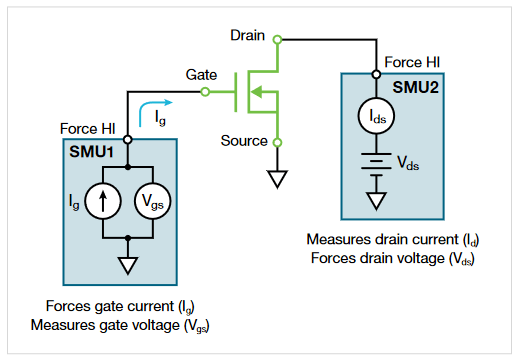
 
2つのソースメジャーユニット(SMU)機器を使用したMOSFETゲートチャージテスト構成
図3. 2つのSMUを使用したゲート電荷測定の構成
 

クラリウス+ ソフトウェアでのゲート電荷測定の設定

ゲート電荷測定は、テストライブラリとプロジェクトライブラリの両方に置かれ、これは、“gate charge” というキーワードで検索することによって選択枠から見つけることができる。テストライブラリでテストが見つかると、それを選択しプロジェクトツリーに追加することによって、プロジェクト上で運用できる。このテストは、gate_chargeユーザライブラリのgate_charge ユーザモジュールから作成されている。

入力パラメータ

テスト実行前に、クラリウスソフトウェアのConfigure画面(図4)で入力テストパラメータを入力する。入力パラメータはデバイスおよび、どのモデルのSMUが使用されるかに依存する。
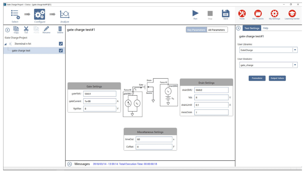
 
Keithley Clarius ソフトウェアの構成ビューで MOSFET ゲートチャージテストを設定する
図4. Configure画面のゲート電荷測定
 

表1に 入 力 パ ラ メ ー タ の 説 明 を 示 す。 ま ず、MOSFETの ゲ ート(gateSMU)とドレイン(drainSMU)に接続されたSMU番号を入力する。ソース端子を常にGNDUまたはForce LOに接続する。

gateCurrent (Ig) パラメータは、ゲートSMUによってゲートに印加される電流の大きさを示す。ドレイン電圧(Vds)は、ドレインに印加されるバイアス電圧であり、drainLimitIはドレインSMUのコンプライアンス電流である。

Coffsetは、オフセットキャパシタンスを補正するために使用され、次にそれを解説する。

表1. gate_charge ユーザモジュールの入力パラメータ

入力パラメータ 値の範囲 デフォルト値 概要
gateSMU SMU1-SMU9 SMU1 ゲート端子に接続されたSMU番号
drainSMU SMU1-SMU9 SMU2 ドレイン端子に接続されたSMU番号
ソース GNDU GNDU ソース端子は常にGNDUのForce LO端子に接続
Vds ±200V 10 V ドレインSMUのドレインバイアス電圧の大きさ
drainLimitI 4200-SMU: 0.1A
4210-SMU: 1 A
0.1 A ドレインSMUの電流コンプライアンス
gateCurrent ± 1E-5 A 1e-7 A ゲートSMUのゲート電流の大きさ
VgsMax ±200V 10 V ゲートSMUの最大電圧
タイムアウト 0~300 s 60 s タイムアウト時間
measDrain 1 (yes) or 0 (no) 1 ドレイン電流値を返す
Coffset 0 or Ceff 0 オープン回路でテストを実行し、シートに返された


オフセット容量の補正

測定システムのケーブル配線および接続に応じて、一桁pFから数百pFの範囲でオフセット容量が存在する。これらの容量は、オープン回路でgate_charge ユーザモジュールを実行し、オフセット容量を求め、補償用ソフトウェアのオフセット容量値に入力することで補正することができる。これらのステップの実行方法を次に示す。

  1. オフセット容量を測定する. 入力ゲート電流を含むテストパラメータを、あたかもデバイスがSMUに接続されたかのように設定する。Ceff 測定に対しVgsMaxを増加させる。試験を行う前に、プローブを持ち上げるか、テストフィクスチャーからデバイスを取り外す。オープン回路でゲート電荷測定を実行する。
  2. オフセット容量を求めるテストの実行後、オフセット容量値が計算され、シートのCeff 列に表示される。Ceffは、最大ゲート電圧、ゲート電流、および時間から導出される。このステップ中はオープン回路が測定されるため、テストが実行された後、シートに-9または-12のテストステータス値が表示される。これは、デバイスが測定されないことにより平坦領域が存在しないためである。しかし、そのCeff 値は正しく、Configure画面にCoffsetとして入力する。
  3. 測定されたオフセット容量を入力し、実行する. Configure画面にCoffsetの測定オフセット容量Ceff を入力する。デフォルトでは、Coffsetは0Fである。後に続く読み取り処理でオフセット容量に対して補償が行われる。

テストの実行

入力パラメータを入力し、画面上部のRunを選択してテストを実行する。テストが実行されると、ゲート電荷波形はAnalyze画面のグラフにリアルタイムで更新され、計算された出力パラメータはシートに表示される。

出力パラメータ

テスト完了後、いくつかのパラメータがシートに返される。表2にそれらのパラメータを解説する。

表2. gate_charge ユーザモジュールの出力パラメータ

 
出力パラメータ 概要
gate_charge テストステータス値-説明については表3を参照
timeArray 計測時間(秒)
VgArray ゲート・ソース間電圧測定値(ボルト)
VgCharge ゲート電荷測定値(クーロン)
VdArray ドレイン電圧測定値(ボルト)
IdArray ドレイン電流測定値(アンペア)
スロープ ゲート電圧の動的傾き(dVg/dt)
Ceff 最大ゲート電圧に対するゲート電荷の比率
Vpl 平坦またはミラー電圧(ボルト)
T1 平坦領域が開始するタイムスタンプ(秒)
T2 平坦領域が終了するタイムスタンプ(秒)
Qgs 原点から最初の変曲点、すなわち電圧平坦領域までのゲート電荷(クーロン)
Qgd ゲート電荷曲線の2つの変曲点間のゲート電荷(クーロン)
Qg 原点からVgsMaxまでのゲート電荷(クーロン)


結果のグラフ化

結果として得られるゲート-ソース電圧は、ゲート電荷の関数としてプロットすることができ、また、ドレイン電流およびドレイン電圧は、時間の関数としてプロットすることができる。図5は、4200A-SCSによって生成される典型的なゲート電圧波形である。
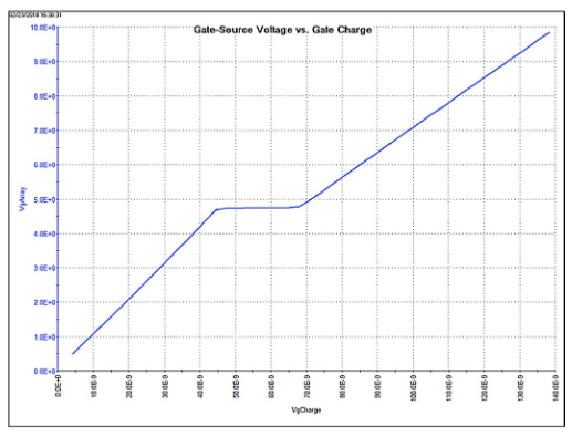
 
Keithley 4200A-SCSパラメータアナライザによって生成されたMOSFETゲート電圧波形
図5. 4200A-SCSによって生成される典型的なゲート電圧波形
 

Vgsのプロットに加えて、VdsおよびIdも、ゲート電荷または時間の関数としてプロットすることができる。図6に、ゲート電荷の関数として3つのパラメータの全てがプロットされたクラリウスソフトウェアのAnalyze画面におけるグラフを示す。この場合、電圧はY1軸上に示され、電流はY2軸上にプロットされる。
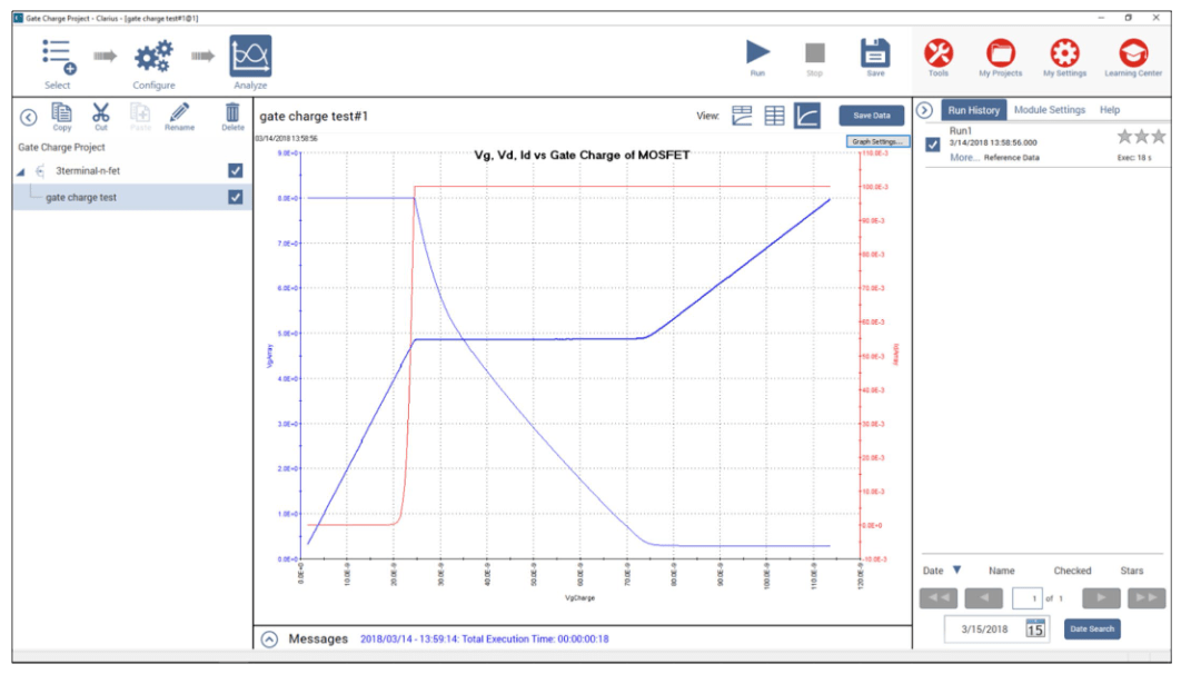
 
MOSFETゲート電荷の経時的関数としてのVgs、Vds、およびId
図6. ゲート電荷に対するVgs、Vdsおよび Idのプロット
 

テストステータスの確認

テストが実行されるたびに、テストステータス値が “gate_charge” と名付けられたシートの第1列に返される。表3に“gate_charge” 列に返されたテストステータス値と、それらの説明および注釈を示す。

表3. テストステータス値

テスト状況 概要
1 エラーなし。 テストは成功。
-1 ゲートSMUなし。 正しいSMUを指定する。
-2 ドレインSMUなし。 正しいSMUを指定する。
-3 VgsMax > 200 V ゲート電圧が200V 未満であることを確認する。ゲート電圧を下げる。
-4 ドレイン電流制限が1A(4210-SMU)を超える。
ドレイン電流制限が0.1A(4200-SMU)を超える。
ドレイン電流が1A(中電力SMUでは0.1A)未満であることを確認する。ドレイン電流制限を下げる(drainLimitI)。
-5 電力の制限を超える。 V>20Vの場合、電流上限を<0.1Aとする。ドレイン電流制限(drainLimitI)またはドレイン電圧(Vds)を減らす。
-6 入力条件のエラーチェック。タイムアウトを200秒に制限する。 タイムアウトを<200秒に指定する。
-7 試験時間が規定のタイムアウト(timeOut)を超える。 タイムアウトを増やす。最大値は200秒。gateCurrentを増やしてデバイスをより高速に充電するように試みる。
-8 反復回数 > 10000 ゲート電流(gateCurrent)を増加させる。
-9 反復回数 < 5 ゲート電流(gateCurrent)を小さくする。デバイス、テストセットアップ、および正しいSMUを確認する。
このエラーが、オフセット補正のオープン回路測定時に発生した場合無視することができる。Ceff 値は有効。
-10 原点から最初の平坦点までの点数が< 10 ゲート電流(gateCurrent)を減らす。
-11 傾きS1の計算エラー。相関係数< 0.9。原点から最初の平坦点までの曲線が直線ではない。 デバイスとテストの設定を確認。
-12 傾きS2の計算エラー。相関係数< 0.9。最後の平坦点からVgsMaxまでの曲線が直線ではない。 デバイスとテストの設定を確認。VgChargeまたはVdArrayが高い場合は、gateCurrentを減らしてテストを繰り返す。
このエラーが、オフセット補正のオープン回路測定時に発生した場合無視することができる。Ceff 値は有効。
-13 Vds > 200 V ドレイン電圧を下げる。
-14 gateCurrent > 10 µA ゲート電流(Ig)を減らす。


結論

トランジスタのゲート電荷測定は、4200A-SCSパラメータアナライザを用いて容易に行うことができる。デバイスのゲートおよびドレインにそれぞれSMUを接続し、クラリウスソフトウェアを使用し、ゲート電荷波形を容易に導出する。

Find more valuable resources at TEK.COM

電子戦装備/レーダ解析に関する参考資料

fig-18
パンフレット

レーダ信号の生成

最高周波数で複雑なレーダ・テスト信号を生成するのに最適なソリューションはどのようなものでしょうか。当社のアプリケーション・ノートでは、レーダ・システムを欺く信号の最適な生成方法を解説しています。

smu
ブログ

高度なレーダ解析:最新レーダの測定用ツール

設計プロセスにおけるテストの不確かさが低減され、複雑化する設計の信頼性を高めることができます。当社のアプリケーション・ノートでは、最新のレーダに必要なツールをご紹介しています。

SMU Group
ブログ

電子対策の検証技法

このウェブ・セミナでは、RSA5100B型やRSA7100B型など、テクトロニクスのリアルタイム・スペクトラム・アナライザを使用して、電子対策(ECM)システムを検証するためのアプローチを詳細に見ていきます。

Noisey gate drive
ブログ

電子対策の検証技法

このウェブ・セミナでは、RSA5100B型やRSA7100B型など、テクトロニクスのリアルタイム・スペクトラム・アナライザを使用して、電子対策(ECM)システムを検証するためのアプローチを詳細に見ていきます。

Mosfet Gate Charge Frequently Asked Questions

What is the drain-source on-resistance of a MOSFET?

MOSFET switching devices operate in the on and off states. In the “on” state, the impedance of the switch is theoretically zero and no power is dissipated in the switch no matter how much current is flowing through it. In the “off” state, the impedance of the switch is theoretically infinite, therefore no current is flowing and no power is dissipated.

Thedrain-source on-resistance (RDS(on)) is the effective resistance between the drain and the source of a MOSFET when it’s in the on state. This occurs when a specific gate-to-source voltage (VGS) is applied. In general, as the VGS increases, the on-resistance decreases. The lower the MOSFET on-resistance, the better because a low resistance reduces undesired power dissipation, improving the power efficiency of the device.

How can I test a MOSFET for drain-source on-resistance on my curve tracer?

Answer: Drain-Source On-Resistance - RDS(on)

What is drain-source on-resistance?

Drain-source on-resistance (RDS(on)) is the resistance between the drain and the source of a MOSFET when a specific gate-to-source voltage (VGS) is applied to bias the device to the on state. As the VGS increases, the on-resistance generally decreases. The measurement is made in the ohmic (i.e. linear) region of the device. Generally speaking, the lower the MOSFET on-resistance, the better.

One of the ways to trace this resistance is to use a curve tracer. On a curve tracer, the so called “Collector Supply” drives the drain while the “Step Generator” drives the gate. For step-by-step instructions on how to test a MOSFET for drain-source on-resistance using a curve tracer, see below. For instructions on how to use an oscilloscope or SMU to measure MOSFET on-resistance, see our “What is the drain-source on-resistance of a MOSFET?” FAQ.

What the display shows:

The display shows VDS on the horizontal axis, and the resulting ID on the vertical axis. The specification is met when at the specified VDS, VDS/ID is less than or equal to the specified maximum.

How to test a MOSFET for drain-source on-resistance on a curve tracer:

1. Under Controls, set:

            A:Max Peak Volts to the lowest setting above the specified VDS

            B: Max Peak Power Watts to the lowest setting that satisfies (ID x VDS)

            C: Collector Supply Polarity to (+DC) for N-channel or (-DC) for P-channel  

            D: Horizontal Volts/Div to display VDS between the 5th and 10th horizontal divisions

            E: Vertical Current/Div to display ID between the 5th and 10th vertical divisions

            F: Number of steps to minimum (zero)

            G: Step Generator to Voltage

            H: Step Generator Polarity to apply forward bias (+ for N-channel), (- for P-channel)

            I: Step/Offset Ampl to approx 50% of the specified VGS

            J: Pulse to Long       

            K: Configuration to (Base/Step Gen, Emitter/Common)

            L: Variable Collector Supply to minimum % (full ccw)

            M: DotCursor ON

2. Apply power to the MOSFET:

            A: Position the Left/Right switch as appropriate

            B: Slowly increase the Variable Collector Supply until the specified VDS is reached

3. Compare to data sheet specifications:

            A: Check that VDS/ID is less than or equal to the specified minimum

Tektronix Curve Tracers are discontinued products. More efficient and accurate methodologies and solutions have been designed to support curve tracing functionality on a much more compact form factor. One such solution is based on using a dual channel SMU or two single channel SMUs and software to control the bias voltage step generation and the relative drain to source voltage drop. To learn more, see our “What is the drain-source on-resistance of a MOSFET?” FAQ.

How do you find the transconductance of a MOSFET?

Transconductance is a key test for validating the MOSFET performance in power electronics designs. It ensures that a MOSFET is functioning properly and helps engineers choose the best one when voltage gain is a key spec for their circuit designs. This, in turn allows companies to take power semiconductor devices to market faster while minimizing failures in the field.

Transconductance is the ratio of drain current (ID) to gate-source voltage (VGS) when a constant drain-source voltage is applied. The current to voltage ratio is commonly referred to as gain. Transconductance is a critical parameter strictly connected with the threshold voltage (VTH) of MOSETs and both are related to the size of the gate channel. The formula for deriving the transconductance of a MOSFET from I-V measurements is:

gm = ΔID / ΔVGS

How to measure transconductance of a MOSFET?

The approach shown in the first configuration calls for three source measure units (SMUs), allowing every node to be held at a feedback-controlled voltage and every current to be measured simultaneously. If you don’t have enough SMU channels to cover each device channel connection, it is possible to proceed as shown in the second configuration. It should be noted that this configuration is more susceptible to a noisy ground connection and can produce ground loops if long cables are used. Also, the current and voltage at the source terminal cannot be measured, which can lead to errors in calculations.

Measuring transconductance

  1. Sweep the gate voltage (VGS) over the desired range, while maintaining a constant drain/source voltage (VDS)
  2. Measure the drain current (ID) at each increment step of VGS.
  3. Calculate transconductance (gm) by dividing the small changes in the current ID by the small changes in VGS.

The red plot line shown here illustrates the transconductance (gm) and the maximum transconductance value (Vth).

Learn more about safe, precise and fast MOSFET device characterization tests.

How can I test a MOSFET for Zero Gate Voltage Drain Current on my curve tracer?

Answer: Zero Gate Voltage Drain Current - IDSS

What is Zero Gate Voltage Drain Current? 

Zero gate voltage drain current is the ID that flows when VGS=0.  It’s the on-state current in a depletion mode MOSFET and the off-state current in an enhancement mode MOSFET.

On the IV curve tracer, the Collector Supply drives the drain and the gate is shorted to the source so that VGS=0.

What The Display Shows:

The display shows VDS on the horizontal axis, and the resulting ID on the vertical axis.  The specification is met when with VGS=0 and the specified VDS applied, ID is less than or equal to the specified maximum.

How To Do It:

1. Set controls:

            A:Max Peak Volts to the lowest setting above the specified VDS

            B: Max Peak Power Watts to the lowest setting that satisfies (ID x VDS)

            C: Horizontal Volts/Div to display VDS between the 5th and 10th horizontal divisions

            D: Vertical Current/Div to display the ID between the 5th and 10th vertical divisions

            E: Collector Supply Polarity to (+DC) for N-channel or (-DC) for P-channel

            F: Configuration to (Base/Short, Emitter/Common)

            G: Variable Collector Supply to minimum % (full ccw)

            H: DotCursor ON

2. Apply power to the MOSFET:

            A: Position the Left/Right switch as appropriate

            B: Slowly increase the Variable Collector Supply % until the specified VDS is reached

3. Compare to data sheet specifications:

            Check that at the specified VDS, ID is less than or equal to the specified maximum

How can I test a MOSFET for Gate Threshold Voltage on my curve tracer?

Answer: Gate Threshold Voltage - VGS(th)

What is Gate Threshold Voltage? 

Gate threshold voltage is the lowest VGS at which a specified small amount of ID flows.  The test is run with VGS = VDS.

On the curve tracer, the Collector Supply provides VDS.  Patch cords are used to short the gate to the drain so that VGS=VDS.

What The Display Shows:

VGS is displayed on the horizontal axis, and the resulting ID is displayed on the vertical axis.  The specification is met when, at the specified ID, VGS is within the min/max limits.

How To Do It:

1. Set controls:

            A: Max Peak Volts to the lowest setting above the specified VGS

            B: Max Peak Power Watts to the lowest setting that satisfies (ID x VDS)

            C: Horizontal Volts/Div to display VGS between the 5th and 10th horizontal divisions

            D: Vertical Current/Div to display the specified  ID between the 5th and 10th vertical divisions

            E: Collector Supply Polarity to (+DC) for N-channel or (-DC) for P-channel

            F: Configuration to (Base/Open, Emitter/Common)

            G: Variable Collector Supply to minimum % (full ccw)

            H: DotCursor ON

2: Attach patch cords:

            A: Connect a patch cord between the base and collector terminals on the unused side of the interface area

            B: Connect a second patch cord between the base sense and collector sense terminals on the unused side of the fixture area

3. Apply power to the MOSFET:

            A: Position the Left/Right switch to Both

            B: Slowly increase the Variable Collector Supply % until either the specified ID or the maximum threshold voltage is attained – whichever comes first

4. Compare to data sheet specifications:

            Check that the gate threshold voltage is within the specified min/max limits

How can I test a MOSFET for Transconductance (gFS) and Forward Admittance on my curve tracer?

Answer: Transconductance (gFS) and Forward Admittance

What is Transconductance and Forward Admittance? 

Transconductance is the ratio of ID to VGS.  The I/V ratio is commonly referred to as gain.

On the curve tracer, the Collector Supply drives the drain and the Step Generator drives the gate.

What The Display Shows:

The display shows VDS on the horizontal axis, and the resulting ID on the vertical axis.  With the Step Generator providing gate drive, the curve will be displaced upward from the horizontal axis as the gate drive causes a proportional ID.  The specification is met when, at either the specified VGS or the specified ID, the ratio of ID to VGS is equal to or greater than the specified minimum.

How To Do It:

1. Set controls:

            A:Max Peak Volts to the lowest setting above the specified VDS

            B: Peak Power Watts at the lowest setting to satisfy (ID x VDS)

            C: Collector Supply Polarity to (+DC) for N-channel or (-DC) for P-channel

            D: Horizontal Volts/Div to display the specified VDS between the 5th and 10th horizontal divisions

            E: Vertical Current/Div to display the specified ID between the 5th and 10th vertical divisions

            F: Number of steps to minimum (zero)

            G: Step Generator to Voltage

            H: Step Generator Polarity to apply forward bias  (+ for N-channel),  (- for P-channel)

            I: Step/Offset Ampl to approx 1% of the specified VDS

            J: Pulse to Long       

            K: Configuration to (Base/Step Gen, Emitter/Common)

            L: Variable Collector Supply to minimum % (full ccw)

            M: DotCursor ON

2. Apply power to the MOSFET:

            A: Position the Left/Right switch as appropriate

            B: Slowly increase the Variable Collector Supply % until the specified  VDS is reached

3. Adjust to parameters:

            Press and hold Offset Aid until an appreciable vertical displacement of the   curve occurs. It will be necessary to readjust Variable Collector % to maintain VDS.  Continue adjusting Step Offset and VDS alternately until the specified operating point is reached.

4. Calculate transconductance (gFS):

             Read gFS directly from the cursor readout

5. Compare to data sheet specifications:

              Check that the value is equal to or greater than the specified minimum

Forward admittance is an alternative way of expressing transconductance and is measured by setting the curve tracer up to measure transconductance (as above), switching Horizontal Volts/Div to STEP GEN, using SWEEP to complete the curve, then changing the cursor to F line and positioning the slope of the F line until it’s tangent to the curve.

How can I test a MOSFET for On-State Drain Current on my curve tracer?

Answer: On-State Drain Current - ID(on)

What is On-State Drain Current?

On-state drain current is ID with a specified VGS to bias the device to the on-state.  The measurement is made in the ohmic (i.e. linear) region of the device.

On the curve tracer the Collector Supply drives the drain and the Step Generator drives the gate.

What The Display Shows:

The display shows VDS on the horizontal axis, and the resulting ID on the vertical axis.  The specification is met when at the specified VDS, ID is greater than or equal to the specified minimum.

How To Do It:

1. Set controls:

            A:Max Peak Volts to the lowest setting above the specified VDS

            B: Max Peak Power Watts to the lowest setting that satisfies (ID x VDS)

            C: I: Collector Supply Polarity to (+DC) for N-channel or (-DC) for P-channel  

            D: Horizontal Volts/Div to display VDS between the 5th and 10th horizontal divisions

            E: Vertical Current/Div to display ID between the 5th and 10th vertical divisions

            F: Number of steps to minimum (zero)

            G: Step Generator to Voltage

            H: Step Generator Polarity to apply forward bias (+ for N-channel),  (- for P-channel)

            I: Step/Offset Ampl to approx 50% of the specified VGS

            J: Pulse to Long       

            K: Configuration to (Base/Step Gen, Emitter/Common)

            L: Variable Collector Supply to minimum % (full ccw)

            M: DotCursor ON

2. Apply power to the device:

            A: Position the Left/Right switch as appropriate

            B: Slowly increase the Variable Collector Supply until the specified VDS is reached

3. Compare to data sheet specifications:

            A: Check that ID is equal to or greater than the specified minimum

How can I test a MOSFET for drain-source breakdown voltage on my curve tracer?

Answer: Drain-Source Breakdown Voltage - V(br)DSS

What is Drain-Source Breakdown Voltage?

Drain-source breakdown voltage is the VDS at which a specified value of ID flows, with VGS=0.  Since it's the reverse current through a pinched-off channel, ID exhibits a knee shaped rise, increasing rapidly once breakdown occurs.

On the curve tracer, the Collector Supply drives the drain and the gate is shorted to the source so VGS=0.

What The Display Shows:

The display shows VDS on the horizontal axis, and the resulting ID on the vertical axis.  The specification is met when, at the specified ID, VDS is greater than or equal to the specified minimum.

How To Do It:

1. Set controls:

A: Max Peak Volts to the lowest setting above the specified minimum

     VDS

            B: Max Peak Power Watts to the lowest setting that satisfies (ID x VDS)

            C: Horizontal Volts/Div to display VDS between the 5th and 10th horizontal divisions

            D: Vertical Current/Div to display ID between the 5th and 10th vertical divisions                  

            E: Collector Supply Polarity to +Leakage (for N-channel) or -Leakage (for P-channel)

            F: Configuration to (Base/Short, Emitter/Common)

            G: Variable Collector Supply to minimum % (full ccw)

            H: DotCursor ON

2. Apply power to the MOSFET:

            A: Position the Left/Right switch as appropriate

            B: Slowly increase the Variable Collector Supply % until the specified ID is attained

3. Compare to data sheet specifications:

            Check that at the specified ID, VDS is greater than or equal to the specified minimum

How can I test a MOSFET for Forward Gate Body Leakage Current on my curve tracer?

Answer: Zero Gate Voltage Drain Current - IDSS

What is Zero Gate Voltage Drain Current?

Zero gate voltage drain current is the ID that flows when VGS=0.  It’s the on-state current in a depletion mode MOSFET and the off-state current in an enhancement mode MOSFET.

On the curve tracer, the Collector Supply drives the drain and the gate is shorted to the source so that VGS=0.

What The Display Shows:

The display shows VDS on the horizontal axis, and the resulting ID on the vertical axis.  The specification is met when with VGS=0 and the specified VDS applied, ID is less than or equal to the specified maximum.

How To Do It:

1. Set controls:

            A:Max Peak Volts to the lowest setting above the specified VDS

            B: Max Peak Power Watts to the lowest setting that satisfies (ID x VDS)

            C: Horizontal Volts/Div to display VDS between the 5th and 10th horizontal divisions

            D: Vertical Current/Div to display the ID between the 5th and 10thvertical divisions

            E: Collector Supply Polarity to (+DC) for N-channel or (-DC) for P-channel

            F: Configuration to (Base/Short, Emitter/Common)

            G: Variable Collector Supply to minimum % (full ccw)

            H: DotCursor ON

2. Apply power to the MOSFET:

            A: Position the Left/Right switch as appropriate

            B: Slowly increase the Variable Collector Supply % until the specified VDS is reached

3. Compare to data sheet specifications:

            Check that at the specified VDS, ID is less than or equal to the specified maximum