Introduction
Capacitance-voltage (C-V) and AC impedance measurements are commonly performed on many types of devices for a wide variety of applications. For example, C-V measurements are used to determine these device parameters:
- Gate oxide capacitance of MOSCAPs
- MOSFET input and output capacitance
- Built-in potential of solar cell
- Majority carrier concentration of a diode
- Capacitance between terminals of a BJT
- Oxide thickness, doping density, and threshold voltage from a MIS capacitor
Both the 4215-CVU and 4210-CVU are multi-frequency (1 kHz to 10 MHz) AC impedance measurement modules for the 4200A-SCS Parameter Analyzer (see Figure 1) that enables the user to make C-V measurements easily.The differences between the two CVUs are the number of test frequencies and the AC drive voltage. The 4215-CVU has 10,000 discreet frequencies with 1 kHz resolution and the 4210-CVU has 37 discreet frequencies. The AC drive voltage range of the 4215-CVU is 10 mV to 1 V rms and the range of the 4210-CVU is 10 mV to 100 mV rms.

formulator, filtering, timing controls, and the ability to switch the AC ammeter terminal in the software. These tools, along with using proper cabling and C-V measurement techniques, allow the user to make highly sensitive capacitance measurements.
This application note describes how to make optimal capacitance measurements using proper measurement techniques and the CVU Capacitance Voltage Unit.
CVU Measurement Overview

Figure 2 shows a simplified model of the 4210-CVU and 4215-CVU. The capacitance of a device is determined by sourcing an AC voltage and measuring AC current and phase while a DC voltage is applied or swept across the device.
The time domain AC values are processed into the frequency domain to produce the phasor form of the impedance. The device capacitance is calculated from the AC impedance and the test frequency using this equation:

The CVU measures capacitance using the auto-balance bridge (ABB) method. The ABB is used to nullify an AC signal of known frequency on one terminal (LPOT if the AC ammeter is on LCUR) of a DUT to guard out stray impedances. This AC ground keeps the LPOT terminal of the CVU at 0 VAC, so that all the AC current in the test circuit flows to the AC ammeter and not through any parallel capacitances in the test circuit.
Depending on the test settings, which include the frequency, AC drive voltage, and current range, the CVU can measure capacitances in the sub-picofarad to millifarad ranges. The user-specified test frequency depends on the device being tested and the parameters being derived. The range of test frequencies is from 1 kHz to 10 MHz. The DC bias function is ±30 V (60 V differential).
Measurement Models and Parameters
Typical models of a measurement DUT are usually a series or parallel resistancecapacitance (RC) circuit. As shown in the simplified models in Figure 3, the CVU can measure the DUT as a series configuration (RSCS) or as a parallel configuration (RPCP).

The CVU can measure and display these parameters:
- Impedance and phase angle (Z, Theta)
- Resistance and reactance (R+jX)
- Parallel capacitance and conductance (CP–GP)
- Series capacitance and resistance (CS–RS)
- Parallel capacitance and dissipation factor (CP–D)
- Series capacitance and dissipation factor (CS–D)
- Admittance and phase angle (Y, theta)
By using the built-in Formulator tool in Clarius, other parameters such as inductance can be easily extracted from the measured data. The vector diagram for Impedance in Figure 4 shows the fundamental equations for impedance.

AC Impedance Measurement System
A C-V measurement system, as shown in Figure 5, can be quite complicated because the configuration includes the measuring instrument and software, the cabling of the signal path, test fixturing, and the device. To make optimal measurements, the test settings and timing parameters of the CVU need to be set appropriately. Proper cabling, probers, and test fixtures must be used, and then connection compensation must be performed. Finally, the device itself can cause problem measurements. The next few sections will discuss hardware and software considerations for making good capacitance measurements.

Cabling and Connections
This section describes using the proper cabling and connections, AC guarding of the chuck and device terminals, and configuring the AC ammeter terminal.
Proper Cabling
For the best measurement results, use only the supplied red SMA cables for making connections to the CVU. The following accessories are supplied:
(4) CA-447A SMA to SMA 1.5 m cables (red)
(4) CS-1247 SMA to BNC Adaptors
(2) CS-701A BNC Tees
(1) Torque wrench to tighten SMA cable connections
The supplied accessories allow connecting to a test fixture or prober with BNC or SMA connections. The CVU, as well as the supplied accessories configured for two-wire sensing, are shown in Figure 6. A CS-1247 SMA-to-BNC Adaptor is connected to each CA-447A SMA-to-SMA Cable. HCUR and HPOT terminals are connected by a CS-701A BNC tee to form CVH, and LCUR and LPOT are connected together to form CVL. Using the supplied torque wrench, tighten the SMA cable connections to ensure good contacts. The red SMA cables are 100 Ω. Two 100 Ω cables in parallel are 50 Ω, which is standard for high frequency sourcing and measuring applications.

An example of four-wire sensing to the DUT is shown in Figure 7. In this case, the HCUR and HPOT terminals are connected to one end of the device, and the LPOT and LCUR terminals are connected to the other end of the device. To improve the bandwidth, connect the outside shields of the coax cables to the metal test fixture. Use four-wire connections to the device to facilitate sensitive measurements by sensing the voltage as close as possible to the device. The outside shields of each of the four coax cables must be connected as close as possible to the device to minimize the loop area of the shields. The outside shields of the coax cables also get connected to the metal test fixture to reduce noise and coupling from external sources. This reduces the inductance and helps to avoid resonance effects, which can be burdensome at frequencies higher than 1 MHz.

Figure 8 shows a ground jumper connecting the commons of two prober cable assemblies. Keithley Instruments has a series of 4210-MMPC Multi-Measurement Cable Kits for various probers that enable the common connections of various manipulators.

In general, proper cabling is crucial to making successful capacitance measurements. Here are some potential cabling problems:
- Mismatched length on different CVU terminals
- Improper cable impedance (not using red SMA cables)
- Shield connections of all the cables not connected or not connected close enough to the DUT
- Bent, crimped or flattened cables
- SMA cable connectors not making good contact
- Not choosing the proper cable length in the Configure view of the Clarius software
Guarding the Chuck
Guarding can reduce the effects of parallel impedance, or stray capacitance, on capacitance measurement accuracy. The guard terminal is the outside shield of the coax connectors of the CVU. This guard terminal of the CVU should not be confused with the 4200A-SCS’s GNDU terminal, which is connected to chassis ground.
When making C-V measurements between two terminals on the top of the wafer, it may be necessary to guard the chuck to reduce parallel capacitance between the terminals of the DUT and the chuck. In Figure 9, the stray capacitance is reduced by connecting the guard, the shields of the coax cables, to the chuck. For C-V measurements on devices that use the backside of the wafer as a contact, such as is the case for MOSCAPs, the chuck cannot be connected to guard.

Guarding Device Terminals
To measure the capacitance between two terminals on a device with three or more terminals, it is important to guard the third terminal to prevent unwanted capacitances from affecting the measurement accuracy. This is best illustrated through an example. As shown in Figure 10, the CVU is connected to measure the capacitance between the Base and Emitter (CBE) of a BJT.

However, the series combination of capacitance between the other terminals (CBC and CCE) is in parallel with CBE and creates an AC leakage path that can lead to erroneous readings. This parallel capacitance from the other terminals will affect the measurement (CMEAS) as follows:

To prevent the stray capacitance from affecting the measurement accuracy, the Collector is guarded by connecting it to the outside shield of the coax cable, which is at 0 VAC. This is illustrated in Figure 11. This AC guard routes the leakage capacitance current away from the AC current measurement terminal (LCUR), so that only the AC current due to CBE is measured.

Using the 4200A-CVIV Multi-Switch to Guard Device Terminals
Guarded C-V measurements can be automated using the optional 4200A-CVIV Multi-Switch, shown in Figure 12. The CVIV enables the user to switch automatically between I-V (SMU) and C-V (CVU) measurements on a device, as well as connect C-V guard to any terminal on the DUT.

Figure 13 shows the CVHI, CVLO, and CV Guard terminals of the CVU connected to the three terminals of the BJT through the outputs of the 4200A-CVIV. In this example, the CV Guard is switched through Channel 3 of the 4200A-CVIV to the collector terminal of the BJT so that the base-emitter capacitance can be measured between CVHI and CVLO.

The Clarius software allows users to change the output of the 4200A-CVIV automatically so that any of the terminals of the device can be guarded. Figure 14 shows the CVIV MultiSwitch Channel Config settings in Clarius.

AC Ammeter Connections
By default, the LCUR terminal of the CVU is the AC Ammeter connection, and the HCUR terminal is the AC Source Voltage terminal (as shown in Figure 2). However, users have the option to change the function of the terminals in the Advanced Terminal Settings window in the Clarius software as shown in Figure 15. Without the need to change cables manually, lift the prober needles, or physically change the test setup, it’s easy to eliminate potential measurement problems by changing the terminal settings in the software.

This feature allows measuring the AC current on the least noisy terminal, which will provide a more useful measurement. It’s also possible to change the terminal to which the DC voltage is applied. The DC voltage can be combined on the same terminal as the AC ammeter, which is ideal for connections to the gate of a MOS capacitor.
To avoid noisy measurements and stray capacitance, always connect the AC ammeter terminal to the terminal of the device that has the least amount of capacitance to ground. In the example shown in Figure 16, the LCUR (AC ammeter) connection is made to Pad 1 because it has less parasitic capacitance to common than Pad 2. In many cases, the user will not know which pad has the least capacitance to ground, but it’s easy to check by reversing the HCUR and LCUR leads in the Advanced Terminal Settings tab and seeing if that produces better results.

Connection Compensation
The CVU is designed to be connected to a prober or test fixture via interconnect cables and adaptors and may be possibly routed through a 4200A-CVIV Multi-Switch or switch matrix to the DUT. This cabling and switch matrix will add parasitic inductance and stray capacitance to the measurements. To correct for offset errors caused by these connections, the Clarius software has a built-in tool to perform compensation. Connection Compensation is a twopart process:
- Acquire the CVU compensation data for open and short corrections. To perform the corrections in Clarius, select Tools and then select CVU Connection Compensation. Select Measure Open or Measure Short. When compensation data is acquired, it is taken at all test frequencies.
- Enable the correction on the Terminal Settings pane of a CVU test.
Open Correction
Open correction is an offset correction for measuring small capacitances or high impedances. Probes must be up or the device removed from the test fixture during the correction. The outside shields of the cables must be tied together during the open correction, as shown in Figure 17.

An example that shows the effects of Open Compensation is illustrated in the C-V curves for a MOSFET in Figure 18. These graphs show the C-V sweeps between the gate and the drain/source/bulk tied together generated with and without Open Compensation. The purple curve is without compensation and the blue curve is with compensation. The difference between the two curves is about 0.23 pF.

Short Correction
Short correction is an offset correct for large capacitance, low impedance, and inductance measurements. Short compensation removes the effect of offsets caused by series resistance and parasitic inductance. Connect a short between all the output terminals, keeping the shields tied together. Use a BNC or SMA barrel to connect the cables together or short the probes together on a metal contact.
Timing Settings
To make successful C-V measurements, it’s important to choose the appropriate timing parameters in the Clarius software. Adjustments to timing parameters can help prevent noisy measurements and allow acquiring readings in equilibrium. Timing adjustments are made in the CVU Advanced Test Settings window in the Configure view, which is shown in Figure 19. The following adjustments can allow for making quiet or settled readings:
Quiet Readings
- Use the Speed mode settings to adjust the measurement window. The longer the measurement time, or window, the less noisy measurements will be. First, try using the Quiet speed mode. If necessary, use the Custom speed which enables the user to set the time of the measurement window. The time of the measurement window can be calculated as follows: Measurement Window = (A/D Aperture Time) * (FilterFactor2 or Filter Count)
- Further information on making very sensitive capacitance measurements can be found in the Keithley Instruments application note, “Making Femtofarad (1e-15f) Capacitance Measurements with the 4215-CVU Capacitance Voltage Unit.”
Settled Readings
- Sweep Delay time allows the device to charge up to equilibrium before taking a measurement.
- Apply a bias voltage for a specified Hold Time at the beginning of a sweep to allow the device to charge up to the first voltage step of the sweep prior to the start of the sweep.

Equilibrium Conditions
The condition of a device when the internal capacitance is fully charged after an applied step voltage is referred to as the “equilibrium” condition. If C-V measurements are made before the device is in equilibrium, inaccurate results may occur. There are two ways to verify if a device is in equilibrium:
- Check the shape of the C-V curve when sweeping from either direction. For example, the C-V curve of a MOSCAP should look the same from accumulation to inversion or from inversion to accumulation. For testing MOSCAPs, further information on choosing Hold and Sweep Delay times can be found in the Keithley application note, “C-V Characterization of MOS Capacitors using the 4200A-SCS Parameter Analyzer.”
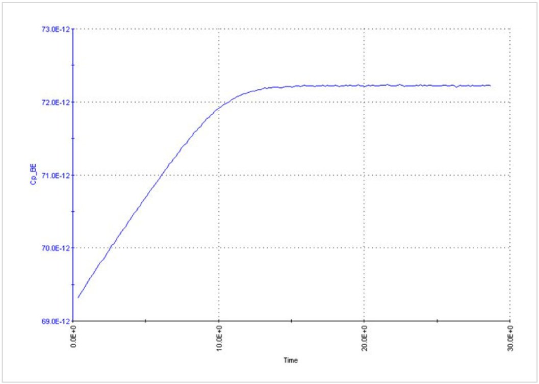
- Set up a test in the Sampling mode to apply a voltage bias and graph the capacitance vs. time of the device. Observe from the graph the time it takes for the device to charge up. For example, the graph in Figure 20 shows a curve of the capacitance vs. time, measured between the emitter and base of a BJT. The applied voltage was 0.5 VDC. From the graph, the equilibrium time is about 13 seconds. Because the equilibrium time is very long for this device, it may be a bad device. This is the process to use to determine the equilibrium time.
Dissipation Factor and Choosing the Correct Measure Model
One way of determining the confidence in capacitance measurements is to check the dissipation factor (D), which is defined as the ratio between the reactance and the resistance of a simple parallel capacitance model. Here is the equation for parallel and series models:

where :
RP = the parallel resistance of the test device in Ω
CP = the parallel capacitance of the test device in F
f = the test frequency in Hz
RS = the series resistance of the test device in Ω
CS = the series capacitance of the test device in F
The parallel capacitance (CP) and series capacitance (CS) are related by the following equation:

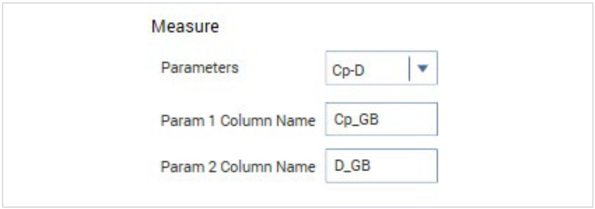
With the CVU, it’s possible to measure the dissipation factor by selecting the CP-D Measure Parameter in the Advanced Test Settings window, as shown in Figure 21.
Ideally, CP and CS should be equal. This will occur if D=0. Even if D is small (<0.1), there is effectively no difference between CP and CS. However, if D is large (>0.1), then it’s necessary either to determine the correct model or troubleshoot the measurements.
If CP and CS are not equal and D is large, it’s possible to determine which model, series or parallel, is correct. Separately measure CP and CS as a function of voltage or frequency. If either of the C-V or C-f curves are flat for CP or CS, then that is the correct model (series or parallel) to use. If none of the curves are flat, then it’s necessary to troubleshoot the measurements to figure out the source of the problem. The problem might be a leaky device, connection issues (cabling), or a device issue such as AC leakage between the pads (may need to use AC guarding).
Troubleshooting
When troubleshooting capacitance measurements, the CVU has built-in tools that can help. In addition to using Cable Compensation, adjusting the AC Ammeter Connections, and setting the appropriate Timing Parameters as previously discussed, other tools in Clarius such as Confidence Check, RealTime Measurements, Status Codes, and Status Indicators are available.
Confidence Check
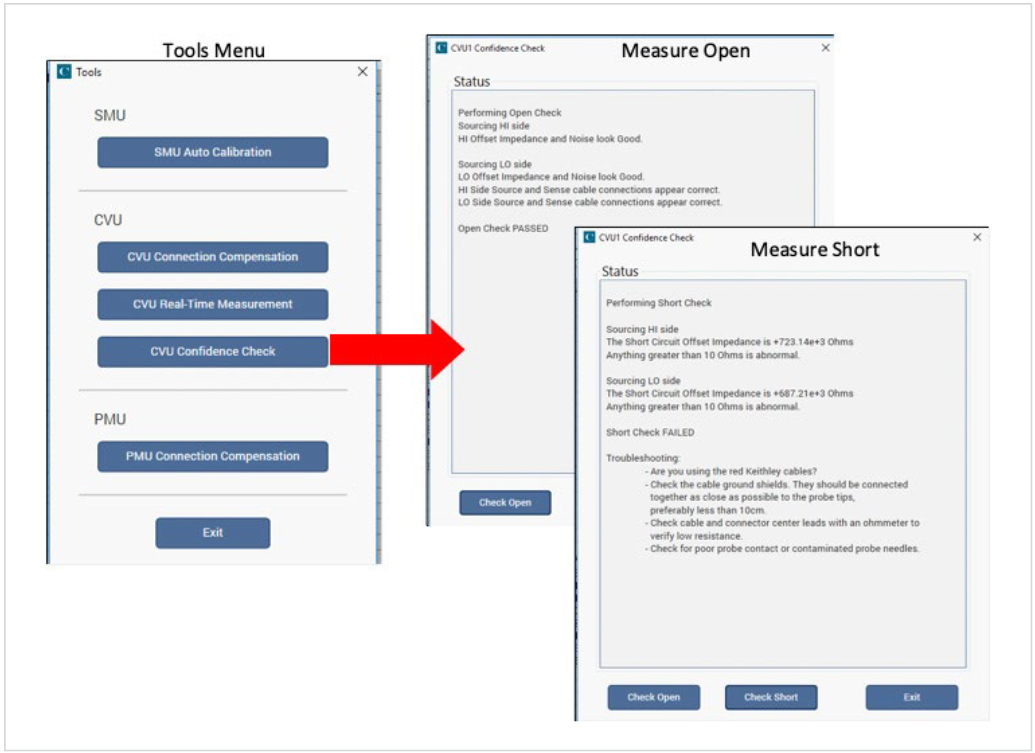
Confidence Check is a diagnostic tool that allows checking the integrity of open and short connections. This is especially important if making measurements through a switch. To enable Confidence Check, select Tools at the top of the Clarius screen.
To verify an open circuit, lift the probes or remove the device from the test fixture. Select Check Open. Follow the instructions and select OK. When the open check is complete, the dialog box displays the results of the test. This process can be repeated to test for a Short after a short is connected. If either test fails, the results include suggestions for troubleshooting. In the example shown in Figure 22, the Open test passed and the Short test failed.
Real-Time Measurements
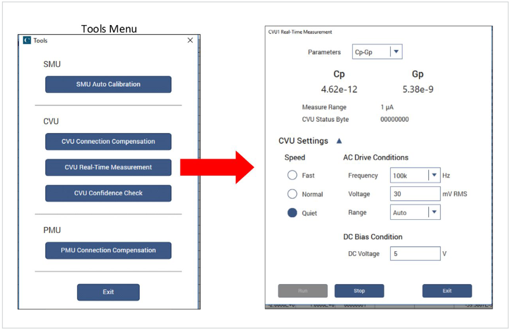
The CVU Real-Time Measurement Mode in the Tools menu provides a direct, real-time user interface to the CVU to help in system setup and debugging. The Real-Time Measurement window is shown in Figure 23. For example, it can be used to confirm that contact has been made from the CVU to the pads on a wafer. Follow these steps to generate real-time measurements:
- Go to the Tools menu
- Select CVU Real-Time Measurement
- Set up the desired parameter settings
- Select Run
- Select Stop to quit taking readings.
Status Indicators
The CVU status code indicates the current measurement range, including an overflow condition, for each reading and flags any errors. When enabled, a data column labeled CVU1S will appear in the Sheet in the Analyze View. Enable status code by selecting Report Status, located in the Advanced Terminal Settings tab in the Configure view.
When a measurement error occurs, the entire row of data in the Sheet related to the measurement changes color. The data values in the flagged data become color-coded, as shown in Figure 24, to identify the error type:
- Red: Measurement Time Out
- Magenta: Measurement Overflow
- Yellow: Auto-Balance Bridge (ABB) not locked

ABB Unlock Errors
The CVU uses the auto-balancing bridge (ABB) technique to achieve accurate impedance measurements. The ABB creates a virtual ground at the DUT to minimize measurement error. Every CVU measurement is made with ABB active. The ABB always attempts to lock the low side of the DUT to virtual ground.
If the ABB fails to lock, the measurement is made but may be out of specification. If this occurs, the returned data is flagged and shown in yellow on the Analyze sheet. Here are the common reasons that the ABB fails to lock:
- The cable lengths connected to the CVU terminals are not the same
- HPOT or LPOT terminals are disconnected
- Excessive noise in the LPOT terminal
- High frequency sources
- Physical cable lengths do not match the cable length set in Clarius
- Improperly torqued SMA cables
- Too much parasitic noise
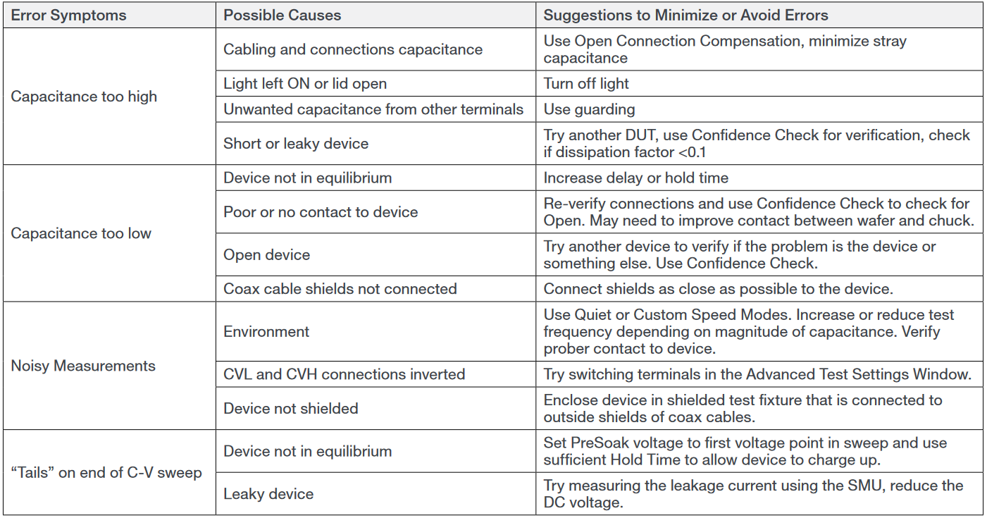
Error Symptoms
Table 1 provides some troubleshooting tips for various measurement problems.
Table 1. C-V Measurement Troubleshooting Table
Conclusion
Good capacitance measurements can be easily achieved using the CVU’s built-in measurement tools, proper cabling and connections, and appropriate measurement techniques. Some of the many built-in tools include compensation, timing parameters, and confidence check.
Find more valuable resources at TEK.COM
Copyright © Tektronix. All rights reserved. Tektronix products are covered by U.S. and foreign patents, issued and pending. Information in this publication supersedes that in all previously published material. Specification and price change privileges reserved. TEKTRONIX and TEK are registered trademarks of Tektronix, Inc. All other trade names referenced are the service marks, trademarks or registered trademarks of their respective companies.
040220 1KW-61528-1

