與我們聯絡
與 Tek 業務代表即時對談。 上班時間:上午 6:00 - 下午 4:30 (太平洋時間)
請致電
與 Tek 業務代表即時對談。 上班時間:上午 8:30 - 下午 5:30 (太平洋時間)
下載
下載手冊、產品規格表、軟體等等:
意見回饋
Key performance specifications
The AWGSYNC01 enables the multi-instrument synchronization of up to four AWG70000 Series units allowing up to eight channels to be aligned to the same clock, pattern jump and trigger inputs. The AWGSYNC01 requires no additional software and allows for the rapid and consistent synchronization of multiple devices. The AWGSYNC01 provides calibration ports to deskew up to four AWG70000 instruments to within ±10ps. After the deskew process the AWGSYNC01 can repeatedly return to within ≤5 ps of the same deskew point.
- Random Jitter (typical): 315 fsRMS
- Total jitter (typical): 13 psp-p at 12.5 Gb/s
- Instrument to instrument skew: ±10 ps
- Skew repeatability/accuracy: ≤5 ps
Key features
- Synchronize signal output from two to four AWG70000 instruments (providing two to eight signal outputs)
- Synchronize to within ±10 ps
- Trigger all channels to the same resolution
Applications
- Wideband RF/MW for communications and defense electronics
- Validation and compliance testing of high speed silicon and communications devices
- Coherent optical research
- Leading edge research in electronics, physics and chemistry
High speed serial
For high-speed serial applications the AWG70000 Series offers the industry's best solution for addressing challenging signal stimulus issues faced by digital designers who need to verify, characterize, and debug complex digital designs. The file-based architecture uses direct synthesis to create complex data streams and gives users a simple, repeatable, and flexible way to solve the toughest signal generation challenges in high-speed serial communication applications. The AWGSYNC01 lets users synchronize multiple AWG instruments to output signals for complex or multi-lane standards such as HDMI and MIPI.
Coherent optical
Today's high speed and increasingly Web-driven world is pushing the demand for short and long haul coherent optical development. Phase modulation, high baud rate, high sample rate, bandwidth, and resolution are all critical to optical applications. Tektronix understands the challenges and inconsistencies of coherent optical testing and offers a reliable, easy to set up and high performance tool set for optical testing, waveform generation and calibration.
Generating the desired signal is only the first challenge in coherent optical. The quality of the signal, low EVM's, and having a clear, open eye is crucial. Complex quadrature modulations, such as PAM-4, require synchronized output from multiple AWG70000 instruments.
The AWGSYNC01 can synchronize multiple single-channel AWG70000 instruments, at the maximum 50 Gs/s sample rate, to output synchronized baseband signals with low EVM and 32 Gbaud performance. The AWGSYNC01 streamlines the complex multiple instrument signal synchronization alignment process, resulting in synchronized signals with a high rate of repeatability and with low jitter.
Research applications
Advanced research applications such as quantum computing, mass spectroscopy, MEMS, NEMS, and particle physics often demand the precise alignment of multiple simultaneous triggering, precompensation, or I/Q generation signals, all with low jitter. AWG70000 series instruments, used with the AWGSYNC01 Synchronization Hub, provide fast and repeatable results. Day to day experimental setups require no additional equipment for synchronization.
The AWGSYNC01 comes with all required phase-stable and delay-matched calibration and clock cabling needed to start synchronizing straight out the box. You can use the clock out signal from the Master AWG70000 instrument to synchronize the output signals, or use an external clock reference signal for higher precision when needed.
Performance you can count on
Depend on Tektronix to provide you with performance you can count on. In addition to industry-leading service and support, this product comes backed by a standard one-year warranty.
Specifications
All specifications are guaranteed unless noted otherwise. All specifications apply to all models unless noted otherwise.
General specifications
- Jitter
- Random Jitter (typical)
- 315 fs RMS
- Total jitter (typical)
- 13 psp-p at 12.5 Gb/s
- Skew
- Instrument to instrument skew (typical)
- ±10 ps
- Skew repeatability/accuracy (typical)
- ≤5 ps
After changes of sample rate or power cycle and within ±5 °C from deskew calibration.
Inputs, outputs
- Calibration Ports
- Four SMA type connectors used to deskew the instrument signal delays. Only use the supplied matched silver calibration cables with these connectors when deskewing the AWG70000 instrument signal outputs.
- Trigger Inputs (A, B)
- External trigger inputs
- Connector
- SMA
- Number of trigger inputs
- 2
- Impedance
- 50 Ω or 1 kΩ selectable
- Polarity
- Positive or negative selectable
- Input voltage range
- 50 Ω: <5 VRMS
1 kΩ: ±10 VRMS
- Threshold range
- -5.0 V to 5.0 V
- Threshold resolution
- 0.1 V
- Minimum trigger pulse width (typical)
- 20 ns
- Trigger holdoff
- >18 μs
- Trigger delay to analog output (typical)
- Asynchronous trigger mode: 32,480 / (2 * fclk) ±20 ns
Synchronous trigger mode: 30,880 / (2 * fclk) ±20 ns
fclk is the frequency of the DAC sampling clock
The DAC sampling clock frequency is displayed on the clock settings tab when the external clock output is enabled.
- Trigger asynchronous jitter (typical)
- 80/sampling clock frequency
The asynchronous jitter performance is directly proportional the sync clock out frequency. The sync clock out is derived from the DAC sampling clock. The DAC sampling clock frequency is displayed on the clock settings tab when the external clock output is enabled.
- Trigger synchronous jitter (typical)
- Clock In = 12.5 GHz: 300 fsRMS, 4.2 ps RJp-p BER@10-12
Variable Reference In = 156.25 MHz: 400 fsRMS, 5.6 ps RJp-p BER@10-12
Fixed Reference In = 10 MHz: 1.7 psRMS, 23.8 ps RJp-p BER@10-12
Sample rate = 25 GS/s
- Sync to AWG (1-4)
- Communication ports used by to synchronize all connected AWG70000 instruments. The AWG70000 connected to Port 1 is the Master AWG70000, which sets up and controls synchronization of the connected instruments. You must connect an AWG70000 to Port 1. AWG70000 instruments connected to Ports 2 through 4 are Slave AWG70000 instruments.
Use the supplied orange cable assemblies to connect these ports to the AWG70000 instruments.
- Clock in from Master AWG
- Synchronizing clock signal input from the master AWG70000 Clock Out port, or from an external clock signal source.
- Connector
- SMA
- Input impedance
- 50 Ω, AC coupled
- Input frequency range
- 6.25 GHz to 12.5 GHz
- Input amplitude (typical)
- +5 dBm to +10 dBm
- Clock Out to AWG Clock In
- Connector
- SMA
- Impedance
- 50 Ω, AC coupled
- Frequency range
- 6.25 GHz to 12.5 GHz
- Output amplitude (typical)
- +5 dBm to +10 dBm
- Sync Clock Out
- Connector
- SMA
- Impedance
- 50 Ω, AC coupled
- Frequency range
- 78.125 MHz to 156.25 MHz
- Output amplitude (typical)
- 1.0 V ±150 mVp-p
- Pattern Jump In
- Number of jump destinations
- 256
- Connector
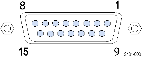
- 15-pin D-sub female connector on rear panel
- Input levels
- 3.3 V LVCMOS
5 V TTL compliant (input impedance pull up to 5 V by 1 kΩ resistor)
- Strobe
- Polarity: Data is clocked in on negative edge
Minimum pulse width: (typical) 64 ns
- Latency to analog output (typical)
- 102,125/fclk +20 ns ± 20 ns
The DAC sampling clock frequency is displayed on the clock settings tab when the external clock output is enabled
- Holdoff time (typical)
- >18 μs
Strobe hold off is the amount of delay required at the end of a waveform before another strobe pulse can be processed
- Connector pin/signal assignment

Pin Signal 1, 6, 8, 9, 14, 15 GND 2 Data bit 0, input 3 Data bit 1, input 4 Data bit 2, input 5 Data bit 3, input 7 Strobe input 10 Data bit 4, input 11 Data bit 5, input 12 Data bit 6, input 13 Data bit 7, input
Physical characteristics
- Dimensions
- Height
- 44.45 mm (1.75 in)
- Width
- 460.5 mm (18.13 in)
- Depth
- 603 mm (23.76 in)
- Weight
- Instrument only
- 5.4 kg (12 lb)
- With packaging
- 9.1 kg (20 lb)
- Cooling clearance
- Top, bottom, left, right
- 0 mm (0 in)
- Rear
- 50 mm (2 in)
- Power
- AC line input
- 100 to 240 V AC, 50/60 Hz
- Consumption
- 110 W
Environment
- Temperature
- Operating
- 0 °C to +50 °C (+32 °F to +122 °F)
- Nonoperating
- -20 °C to +60 °C (-4.0 °F to +140 °F)
- Humidity
- Operating (noncondensing)
- 5% to 90% relative humidity (% RH) at up to 30 °C
5% to 45% relative humidity above 30 °C up to 50 °C
- Nonoperating (noncondensing)
- 5% to 90% relative humidity (% RH) at up to 30 °C
5% to 45% relative humidity above 30 °C up to 60 °C
- Altitude
- Operating
- Up to 3,000 meters (9,843 feet)
Derate maximum operating temperature by 1 °C per 300 meters above 1500 meters
- Nonoperating
- Up to 12,000 meters (39,370 feet)
- Regulatory
- Safety
- UL61010-1, CAN/CSA-22.2, No.61010-1, EN61010-1, IEC61010-1
- EMC Emissions
- IEC61326, EN55011 (Class A), IEC61000-3-2, IEC61000-3-3
- EMC Immunity
- IEC61326, IEC61000-4-2/3/4/5/6/11
- Regional certifications
- Europe: EN61326
Australia/New Zealand: AS/NZS 2064
Ordering information
- AWGSYNC01
- Synchronizes signal output on up to four AWG70000 Series instruments
Standard Accessories
- 071-3292-xx
- AWGSYNC01 Safety and Installation Instructions
- 174-6157-xx
- AWG synchronization communication cable (orange)
- 174-6568-xx
- Phase stable clock cable (blue)
- 174-6606-xx
- Calibration deskew cables (set of 4 cables, silver)
- Power cord
- Specify power cord option at time of order
Warranty
Options
Power plug options
- Opt. A0
- North America power plug (115 V, 60 Hz)
- Opt. A1
- Universal Euro power plug (220 V, 50 Hz)
- Opt. A2
- United Kingdom power plug (240 V, 50 Hz)
- Opt. A3
- Australia power plug (240 V, 50 Hz)
- Opt. A5
- Switzerland power plug (220 V, 50 Hz)
- Opt. A6
- Japan power plug (100 V, 50/60 Hz)
- Opt. A10
- China power plug (50 Hz)
- Opt. A11
- India power plug (50 Hz)
- Opt. A12
- Brazil power plug (60 Hz)
- Opt. A99
- No power cord
Service options
- Opt. C3
- Calibration Service 3 Years
- Opt. C5
- Calibration Service 5 Years
- Opt. R3
- Repair Service 3 Years (including warranty)
- Opt. R3DW
Repair Service Coverage 3 Years (includes product warranty period). 3-year period starts at time of instrument purchase
- Opt. R5
- Repair Service 5 Years (including warranty)
- Opt. R5DW
Repair Service Coverage 5 Years (includes product warranty period). 5-year period starts at time of instrument purchase
- Opt. S1
- On-site Service 1 Year
- Opt. S3
- On-site Service 3 Years (with R or C options)
Cables and accessories are not covered by the instrument warranty and Service Offerings.
Recommended accessories
- AWGRACK
- Rack mount kit for AWG70000 Series instruments and AWGSYNC01


