
All Tektronix Real-Time Spectrum Analyzers can be triggered based on a RF power threshold to help acquire specific signal bursts into memory for analysis. The family of USB-based RSAs include this capability. This blog will review some of the details of the RF Power trigger characteristics and settings to help you most effectively apply triggering to your application. This applies to the RSA306B, as well as all the RSA500A and RSA600A models, the interface shown is SignalVu-PC.
RF Power Trigger Threshold Level and Bandwidth
One of the most common misunderstandings about the RF power trigger is the threshold level setting and what it means. This arises because users will often (incorrectly) set the threshold based on the peak power observed in the spectrum display.

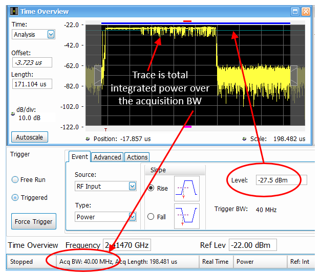
The RF power trigger threshold level is based on the total integrated power across the full 40MHz real-time / acquisition bandwidth of the USB-based RSA. For modulated RF signals, the total integrated power will be higher than the peak of the spectrum trace since it is basically the “area under the curve”. The more bandwidth occupied by the modulated signal, the greater the disparity between the total integrated power vs. the peak of the spectrum trace.
It is usually quite helpful to use the Time Overview display to help set the power trigger, as it will show the total integrated power vs. time for the requested acquisition BW. When the acquisition BW is equal to 40MHz, the trace in the Time Overview gives you a good picture of what the RF Power Trigger circuit is seeing. In addition, the threshold level is graphically illustrated as a horizontal cyan colored line.
One situation that can lead to some confusion is when the set acquisition BW is less than 40MHz. This often happens when setting the span on the RSA to <40MHz to analyze narrowband signals. In this case, the RF Power trigger will still “see” the full 40MHz bandwidth even though the spectrum displays do not, making it possible for the RSA to trigger on a signal that is not visible in the DPX, spectrum or Time Overview displays. This can occur when acquiring narrowband RF signals over the air (OTA), where signals adjacent to the span of interest trigger the RSA. Note that this issue that only applies to the USB RSAs. The RF Trigger bandwidth of the benchtop RSAs (RSA5100B and RSA7100B) follows the acquisition BW setting, as well as offering additional BW control.

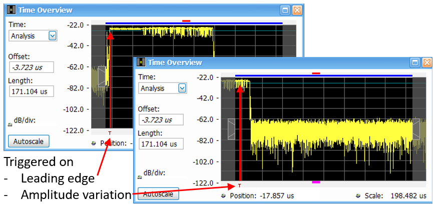
Amplitude variations of the RF signal during the burst, depending on the choice of signal modulation, can also lead to some unexpected triggering issues. If these variations in amplitude cross the threshold level, the RSA may trigger on them instead of the leading edge of the pulse. It all depends on when the RSA re-arms the trigger with respect to the burst repetition rate. The re-arm time will depend on many factors, including the duration of the acquisition, the acquisition BW and the number of analysis displays that are being computed.
This problem can often be mitigated by more carefully adjusting the threshold level, or by changing the trigger slope to trigger on the falling edge instead of the rising edge.
The USB RSAs also offer an external input trigger as well as the ability to trigger at a specific time. The benchtop RSAs offer more comprehensive triggering options, including Frequency Mask Trigger, Spectral Density Trigger, as well as Trigger Delay and Holdoff controls and the addition of Time Qualifications to the trigger events.
Please visit www.tek.com/rsa for more information. You can download of copy of this blog post here.


