Introduction
Semiconductor materials used in power electronics are transitioning from Silicon to Wide Bandgap (WBG) semiconductors such as Silicon Carbide (SiC) and Gallium Nitride (GaN) due to their superior performance at higher power levels in automotive and industrial applications. Due to its high operating voltage levels, SiC technology is finding applications in EV powertrains, whereas GaN is primarily used in fast chargers for laptops, mobile devices, and other consumer devices. This application note illustrates the testing of wide bandgap FETs, but double-pulse testing may be applied to Si devices and MOSFETS or IGBTs.
To ensure reliability of these devices, double pulse testing (DPT) has been developed as an industry standard technique for measuring a range of important parameters during turn on, turn off, and reverse recovery. Systems for double pulse testing include an oscilloscope, signal source and power supplies which must work together to execute tests and produce measurements. This application note describes an example Python script that automates double pulse testing while taking advantage of built-in double pulse testing features of the oscilloscope and function generator. The demo script is provided as a working framework for engineers seeking to automate DPT and is available through the Tektronix GitHub under Programmatic-Control-Examples/Examples/ Oscilloscopes/TekSeriesScopes_HighSpeedDigitizers/ src/DoublePulseTestExample
Using Python allows for a fully automatic test solution including:
- Probe setup configuration
- Channel de-skew configuration
- DC current calibration (e.g. Rogowski coil)
- Vertical setting automatic adjustment
- Horizontal settings automatic adjustment
- Test list creation
- Test results collection
- Test screen/waveform saving
- Repeatable test loop for stability analysis
The Test System
A typical double pulse testing system, shown in Figure 2, is designed to measure low-side automatic switching parameters and timing analysis. For this setup, a 4, 5 or 6 Series B MSO with four or more channels is required. For DPT switching parameters, one needs to measure VDS, ID, and VGSon the low side, therefore three probes are required—two for voltage measurements and one for current measurements. The automation script can also support high-side testing by making high-side connections with appropriate probes.
The gate of the device under test (DUT) is driven by the AFG31000 Arbitrary/Function Generator. Figure 2 shows a high-current power supply driving VDD which is a typcal double pulse testing setup. However, for this low-current example, a Keithley triple output power supply was used to power the gate driver and provide VDD. A photo of the example setup is shown in Figure 3.
The oscilloscope is equipped with Option 5-WBG-DPT, which provides dedicated double pulse measurements with full remote interface access. The WBG software in the scope is also used to control the AFG31000 Arbitrary/ Function Generator and generate gate drive signals. In this example, the PC, oscilloscope and function generator are all connected via LAN (Figure 1).
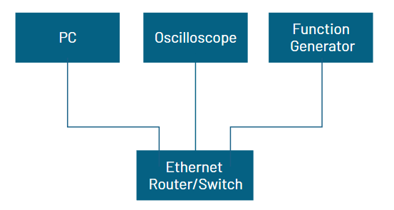
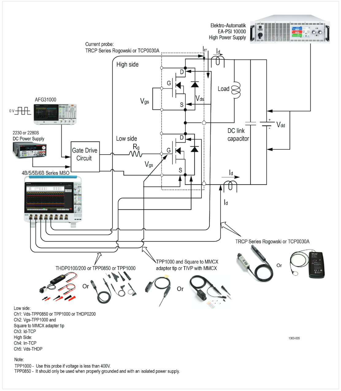
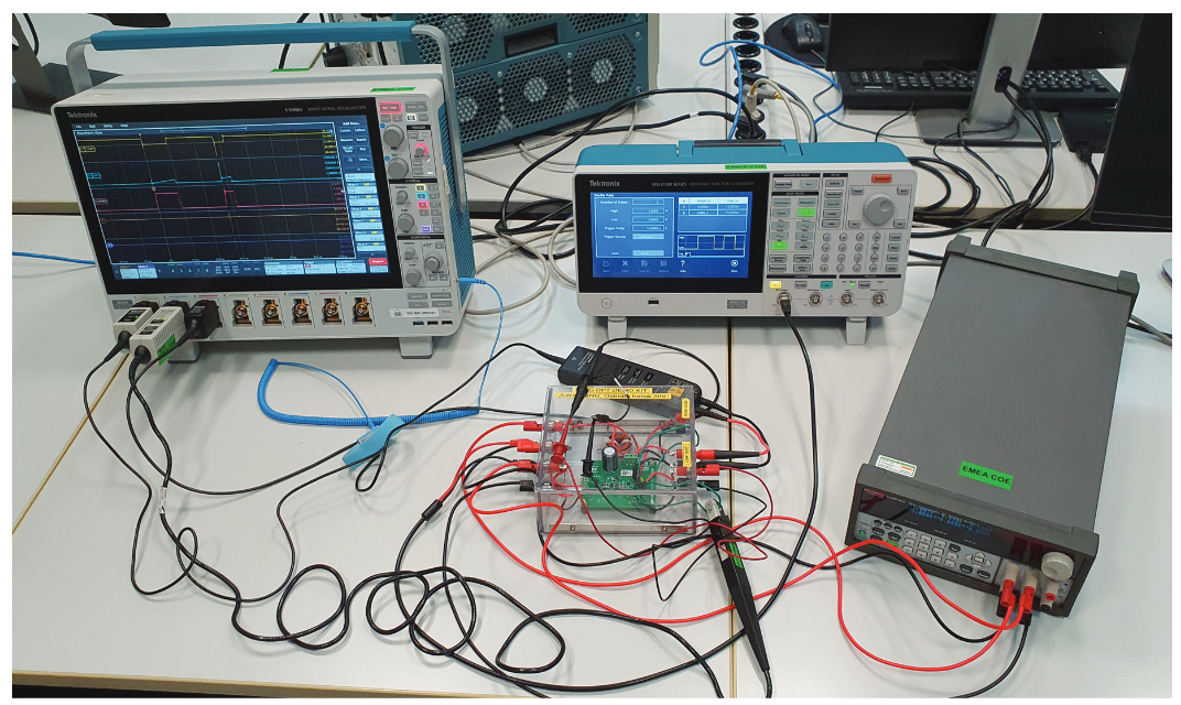
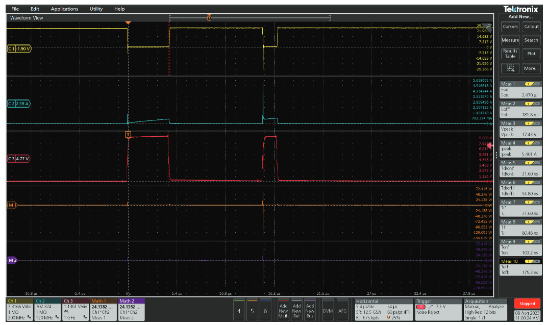
Figure 3 shows the connections of the oscilloscope,function generator and power supply to the DUT. A screen capture (Figure 4) shows the rich set of measurements generated by the DPT analysis software on the oscilloscope.These include:
- Turn-off energy, Eoff
- Peak voltage, Vpeak
- Peak current, Ipeak
- Turn on delay, Td(on)
- Turn off delay, Td(off)
- Rise time, Tr
- Fall time, Tf
- Turn on time, Ton
- Turn off time, Toff
- Slew rate, d/d
Although they are not used in this setup, dead time measurements are also available, to measure the timing between low side and high side switching.
The Test Automation Scripts
This section walks through the example Python script, including the general flow and the functional blocks that make it up. In order to follow the descriptions, download the demo script from the Tektronix GitHub under ProgrammaticControl-Examples/Examples/Oscilloscopes/TekSeriesScopes_HighSpeedDigitizers/src/DoublePulseTestExample
The scripts consist of four major functional blocks:
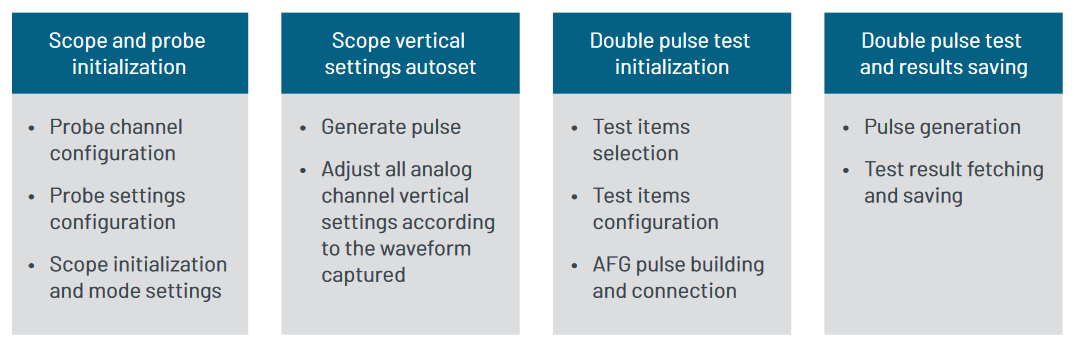
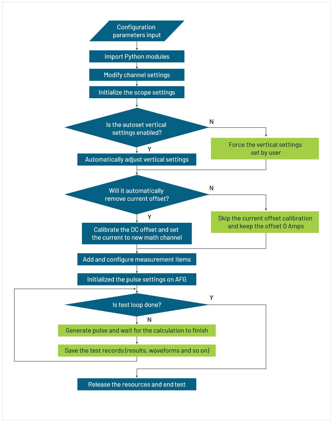
The test process is shown in the following flow chart. In the demo script, test parameters and test switches, such as whether to use autoset for scaling or adjust current channel offset, are set as constants at the beginning of the script. After the initialization section, the instruments are configured, the main loop of the test executes and results are generated.
Descriptions of Functional Blocks
The DPT test automation demo scripts consist of four functional blocks as mentioned previously. This section explains the design concepts and operation of each block.
Regarding the input parameter configuration, please refer to the comments in the “user input settings” section at the beginning of the scripts.
Functional Block 1 - Oscilloscope and probe initialization
This function is used for initialization of the probe and oscilloscope system.
To measure VDS, ID and VGS,two voltage probes and one current probe are needed.
The probe initialization process is as follows:
- Disable Channel 1 and remove channel 1 display from the screen.
- Enable the three channels (two voltage channels and one current channel that the user defined in the parameter settings).
- Set the polarity of the current channel since the user may want to reverse the current direction due to an incorrect connection or other test requirements.
- Set the alternate unit ratio, such as amps/volt if required (for example, when using a shunt resister to measure the current).
- Configure the user-defined channel de-skew parameters in the settings.The scope initialization process is as follows:
The scope initialization process is as follows:
- Recall the default setup if the user defined setting “rst_scope_ena” has been set to 1.
- Enable high-resolution mode to provide more accurate measurement capability.
- Switch the horizontal setting mode to manual mode to set sample rate and record length according to est requirements.
- Calculate the required sample rate based on the user defined pulse setting inputs.
- Set the trigger position according to the user defined value. If the user defined value is less than 0, then the default value of 25 will be used, which means the 25% horizontal location on the screen.
- Set the trigger type to edge trigger.
- Set the trigger source to VGS channel input.
- Set the trigger mode to normal and single trigger.
- Start the acquisition.
Functional Block 2 - Oscilloscope vertical settings and autoset
If the vertical autoset function has been switched on by setting the user defined parameter “autoset_vertical_ena” to 1, then the autoset function will be enabled and the vertical scale and offset will be automatically adjusted for the input signal amplitude.
If the autoset function is disabled, then the vertical settings for all three channels will use the user-defined vertical settings from the parameters input section.
All three channels have their own sub switch to enable/disable the autoset for each channel separately.
The vertical setting autoset procedure is the same for all three channels. The detailed autoset procedure is shown below.
- 1. Initialize the channel scale based on the user-defined input signal amplitude for example, the Vgs is “vgs_amplitude”,Vds is “vds_amplitude”, Id is “id_amplitude”.
- 2. Set the autoset process status flag to 0 and start the loop. When the flag reaches 3, autoset for the current channel is finished and the loop will stop.
- 3. Add “WBGEON” measurement item and configure the AFG in the test item to generate the pulse.
- 4. Enable maximum and minimum measurement for the input channel and set the flag to 1.
- 5. Get the current vertical setting as well as the min and max measurements of the channel input signal.
- 6. Using the user-defined “vertical_autoset_ratio” fast converge the signal amplitude to the valid channel measurement range and set the flag to 2.
- 7. Continue to get the current vertical resolution as well as the min and max value of the channel input. Fine tune the channel scale and offset to fulfill the user defined error range.
- 8. Program the settings and continue doing the same procedure until the user defined target error range has been met.The flag will be set to 3 and the autoset is done.
- 9. Delete the measurement items and end the loop.
For the purposes of this application example, the script includes code to set the vertical settings. However, it is usually easier to use the Preset function in the WBG-DPT package. WBG-DPT Preset simplifies the autoset procedure. It uses user-specified double pulse settings to preset the oscilloscope for optimal Vertical, Horizontal, Trigger, and Acquisition settings. After Preset, one simply runs the gate stimulus from the WBG-DPT measurement panel to generate the double pulse output from AFG 31000.
WBGEON ---- Turn ON energy (Eon)
WBGEOFF ---- Turn OFF energy (Eoff)
WBGVPEAK ---- Vds (peak): Emitter to Collector voltage
WBGIPEAK ---- Id(peak)
WBGTDON ---- td(on) – turn on delay time
WBGTDOFF ---- td(off) – turn off delay time
WBGTR ---- Tr – Rise time
WBGTF ---- Tf – Fall time
WBGTON ---- t(on) – turn on time
WBGTOFF ---- t(off) – turn off time
WBGDDT ---- dv/dt and di/dt
More test items can be supported based on user needs and script modifications.
2. Set the signal sources for each test item.
3. Write settings to the AFG to generate the test pulses. Note that 5 Series B MSO firmware V2.6.38 requires that AFG settings sent through WBG commands be associated with the last measurement configured.
Function block 4 - Double pulse test and saving results
- 1. Start the test loop and generate the pulse by sending the trigger command “WBGGSTIM”.
- 2. Wait until the acquisition is finished.
- 3. Read and display test results of all 11 items on the command line.
- 4. The test results table will be saved into a file on the scope if “remote_table_save_ena” has been set to 1.
- 5. The screen capture will be saved into a file on the scope if “remote_screen_save_ena” has been set to 1.
- 6. The waveforms will be saved into a files on the scope if “remote_wfm_save_ena” has been set to 1.
- 7. The session will be saved into a file on the scope if “remote_session_save_ena” has been set to 1.
- 8. The waveforms will be saved into files on the PC where the Python scripts have been running if “local_wfm_save_ena” has been set to 1.
- 9. The test results table will be saved into a file on the PC where the Python scripts have been running if “local_table_save_ena” has been set to 1.
- 10.Repeat the test until the user defined loop number has been reached.
- 11. Release the resources and end the test.
Reference Documents, Firmware Versions and Python Versions
The SCPI commands used in the scripts can be found in the 4/5/6 Series MSO Programmer Manual at the link below.The part number of the manual at the time of the script design is 07-71305-21.
4, 5, 6 Series MSO Programmer Manual
The user can tailor the scripts to support different test requirements by using the SCPI commands defined in the programmer manual.
The firmware of the 5 Series B MSO used to develop the scripts was V2.6.38.
PyVISA 1.12.0
PyVISA-py 0.5.3
NumPy 1.24.0
More detailed information regarding these packages can be found at the link below.
PyVISA: Control your instruments with Python — PyVISA 1.14.2.dev21+g6bca992 documentation NumPy
Find more valuable resources at TEK.COM
Copyright © Tektronix. All rights reserved. Tektronix products are covered by U.S. and foreign patents, issued and pending. Information in this publication supersedes that in all previously published material. Specification and price change privileges reserved. TEKTRONIX and TEK are registered trademarks of Tektronix, Inc. All other trade names referenced are the service marks, trademarks or registered trademarks of their respective companies.
0724 46W-74074-0