Reinventing High Power Semiconductor Device Characterization
Green initiatives and energy efficiency standards worldwide have motivated engineers to find ways to design more efficient semiconductor devices and integrated circuits. High power semiconductor end applications are becoming increasingly demanding, requiring test instrumentation capable of characterizing significantly higher rated voltages and peak currents than ever before. Keithley offers a broad spectrum of tools, both hardware and software, for power device characterization.
Demand for Higher Power Semi Devices Will Require Pushing Instrumentation to New Extremes
Many segments of the electronics industry, including the semiconductor industry, are focused on increasing energy efficiency, including boosting the efficiency of energy generation, transmission, and consumption. Power semiconductor devices are used as switches or blocking devices in such applications as motor control, voltage regulation and power conversion. New “greener” devices offer lower leakage, lower ON resistance, or both and create new requirements for test and measurement. More ...
| UPSs | High–End Power Supplies, Servers, etc. | HEVEV | Solar Panel Inverters | Industrial Motors | Wind Turbines | Electronic Transmission, Rail Traction, Ships | |
| Main Devices | FETs, IGBTs, Diodes | FETs, Diodes | FETs, IGBTs, Diodes | FETs, IGBTs, Diodes | FETs, IGBTs, Diodes | IGBTs, Diodes | IGBTs, Diodes |
| Peak Current | 2A–100A | 0.5A–10A | 50A–200A | 75A | 3A–100A | >150A | >200A |
| Rated Voltage | 600V–1200V | 600V | 650V–2000V | 600V–1200V | 600V–1200V | Today: 690V, Trend: 3kV–4kV | >5kV |
Testing for Today’s and Tomorrow’s Devices
High power semiconductor end applications are becoming increasingly demanding, requiring test instrumentation capable of characterizing significantly higher rated voltages and peak currents than ever before. Even more significant, breakdown and leakage test are typically performed at 2–3 times the level of the rated or operating voltage. When the devices are in the ON state, they have to pass through tens or hundreds of amps with minimal loss; when they are OFF, they have to block thousands of volts with minimal leakage currents.

At the same time, semiconductor technology is being advanced so that it can operate at much higher levels of voltage, current, power, and frequency. This develops the need for integrating measurement modes for characterizing both transient and steady-state behavior, including rapidly changing thermal effects and capturing voltage and current transients simultaneously. Today’s solutions need to be fast enough to capture and characterize transient behavior without the need to average multiple readings to produce an accurate result.

Building Blocks of Keithley’s High Power Offering

Model 8010 Test Fixture
Provides safe environment for testing at 3kV and at 100A

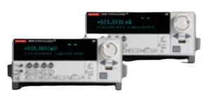
Model 2636B SourceMeter® SMU Instrument
- Two independent SMU channels
- Up to 200V, up to 10A pulsed
- 0.1fA measurement resolution

Model 2657A High Power Source Measurement Unit (SMU) Instrument
- Up to 3000V, Up to 180W of power
- 1fA measurement resolution
- High speed and integrating ADCs

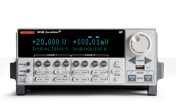
Model 2651A High Power System SourceMeter Instrument
- Up to 50A pulsed (up to 100A with 2 units)
- Up to 2000W pulse / 200W DC power
- Pulse widths from 100µs to DC
- High speed and integrating ADCs
TSP® Express:Web-based plug & play I-V characterization and test software with simple spreadsheet and graphing functionality

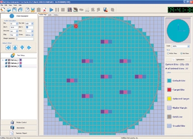
Wafer-level software:ACS
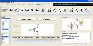
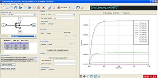
Parametric Curve Tracer software:ACS Basic Edition
High Power Device Characterization with Parametric Curve Tracer Configurations
Characterizing and testing today’s high power semiconductor devices and components is placing a high demand on test equipment. Device design engineers need equipment that can support them throughout the complete lifecycle of a power device. Today, high power characterization systems are available in two main forms - complete turnkey systems and building blocks that must be configured by the user and completed with good software. Turnkey systems can be set up and running quickly, but they can be quite expensive and limited in the breadth of testing that can be performed.
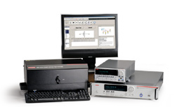
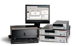
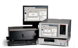
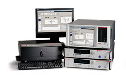
Keithley’s Parametric Curve Tracer configurations are complete solutions configured with a variety of high quality instruments, cables, test fixturing, and software. This building block approach offers the advantages of easy upgrading or modification to meet changing test needs. Additionally, these instruments and accessories can be used across different test system platforms, such as for reliability or device qualification testing.
Keithley’s Parametric Curve Trace configurations include everything necessary for the characterization engineer to develop a complete test system quickly. The configurations supports both parametric and trace test modes, thus including the best of a curve tracer and a parameter analyzer.
Download the Parametric Curve Tracer Configurations datasheet.
Key Facts
- Configurable power levels
– From 200V to 3kV
– From 1A to 100A - Wide dynamic range
– From μV to 3kV
– From fA to 100A - Capacitance-voltage measurement
- DC or pulsed I-V to 50μs
- Test management software includes both trace mode for real-time control and parametric mode for parameter extraction
Applications
- Power semiconductor device characterization and testing
- Characterization of GaN and SiC, LDMOS, and other devices
- Reliability studies on power devices
- Incoming inspection and device qualification


Characterize and Test High Voltage Electronics and Power Semiconductors

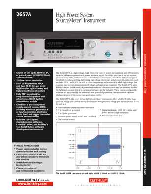
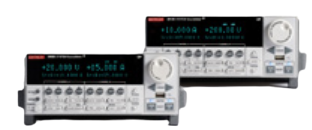
The Model 2657A High Power/High Voltage System SourceMeter® instrument adds high voltage to Keithley’s SourceMeter SMU instruments family of high speed, precision source measurement units. Suitable for R&D, production, and QA/FA, it:
- Sources or sinks up to 3000V @ 20mA or 1500V @ 120mA –able to capture important parametric data that other equipment can’t
- Provides 1fA (femtoamp) current measurement resolution for measuring the lowleakage requirements of next-generation devices
- Eliminates the hassle of integrating power supplies and instruments by combining a precision power supply, current source, DMM, arbitrary waveform generator, V or I pulse generator, electronic 18-bit load, and trigger controller.
Like the Model 2651A, the 2657A comes with dual 22-bit precision ADCs and dual 18-bit 1μs per point digitizers for high accuracy and high speed transient capture. Like other Series 2600A SMU instruments, it includes TSP® Express characterization software, LabVIEW® driver, and Keithley’s Test Script Builder software development environment.
Model 2657A Applications
- Power semiconductor device characterization and testing
- Characterization of GaN, SiC, and other compound materials and devices
- Breakdown and leakage testing to 3kV
- Characterization of sub-millisecond transients
The Model 2657A can source or sink up to 3000V @ 20mA or 1500V @ 120mA.


Keithley offers a broad spectrum of tools, both hardware and software, for power device characterization. A typical device test system could include the high voltage Model 2657A, one or two high current Model 2651A instruments, and up to three low power SMU instruments (other Series 2600A instruments or the Model 4200-SCS semiconductor characterization system). System configuration is made safer and simpler with the optional new Model 8010 High Power Device Test Fixture or individual protection modules. TSP-Link® technology links Series 2600A instruments to form powerful multi-channel systems that rival the system speed of large ATE systems that cost tens of thousands of dollars more.
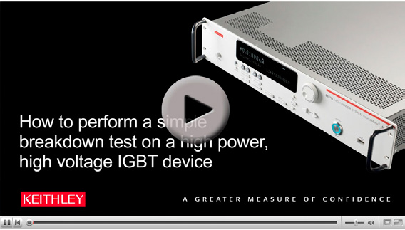
Learn How to Perform a Simple Breakdown Test on a High Power, High Voltage IGBT Device. Click here.
Get Unmatched Performance for Characterizing and Testing High Power, High Current Electronics

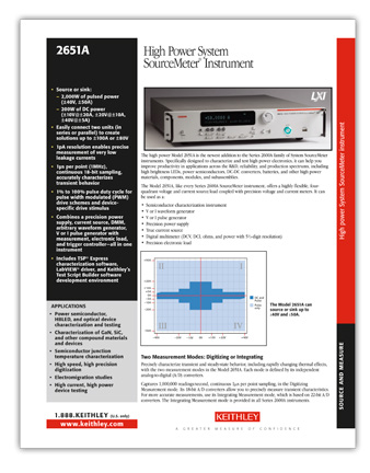
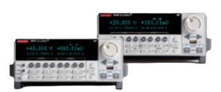
Our new Model 2651A High Power/High Current System SourceMeter® Instrument simplifies characterizing today’s challenging high power electronics with unprecedented power, precision, speed, flexibility, and ease of use. It combines a highly flexible, fourquadrant voltage and current source/load with precision voltage and current meters.
- Source or sink 2,000W of pulsed power (±40V, ±50A), 200W of DC power (±10V@±20A, ±20V@±10A, ±40V@±5A)
- Easily connect two units (in series or parallel) to create solutions up to ±100A or ±80V
- 1pA resolution enables precise measurement of very low leakage currents
- 1μs per point (1MHz), continuous 18-bit sampling, accurately characterizes transient behavior
Choice of digitizing or integrating measurement modes
With the Model 2651A, you can choose from either digitizing or integrating measurement modes for precise characterization of both transient and steady-state behavior. Two independent ADCs define each mode- one for current and the other for voltage-which run simultaneously for accurate source readback without sacrificing test throughput. The digitizing measurement mode’s 18-bit ADCs can support continuous onemicrosecond-per-point sampling, making it ideal for waveform capture and measuring transient characteristics with high precision. The integrating measurement mode, based on 22-bit ADCs, supports applications that demand the highest possible measurement accuracy and resolution. This ensures precise measurements of the very low currents and voltages common in next-generation devices.
Model 2651A Applications
- Power semiconductor, high brightness LED(HBLED), and optical device characterization and testing
- Characterization of GaN, SiC, and other compound materials and devices
- Semiconductor junction temperature characterization
- Reliability testing
- High speed, high precision digitization
- Electromigration studies
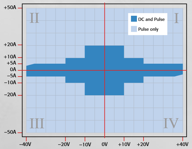
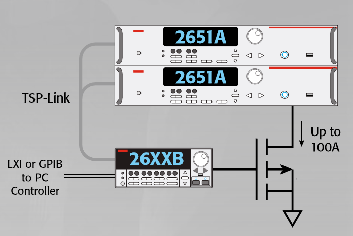
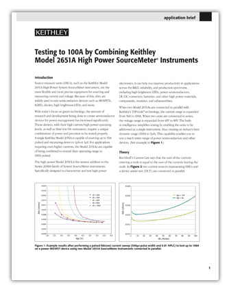
A single Model 2651A unit can source and sink up to ±40V and ±50A. Connect two units in parallel via the builtin TSP-Link expansion bus to extend the system’s current range to 100A or connect them in series to expand the voltage range to 80V. The embedded Test Script Processor (TSP®) included simplifies testing by allowing you to address multiple units as a single instrument so that they act in concert. The built-in trigger controller can synchronize the operation of all linked channels to within 500 nanoseconds.
Built for building systems. The embedded TSP controller and TSP-Link interface in each Series 2600A instrument make it easy to link multiple Model 2651As and other Series 2600A instruments to create an integrated test system with up to 64 channels. Precision timing and tight channel synchronization are guaranteed with built-in 500ns trigger controllers. The fully isolated, independent channels of Series 2600A instruments allow true SMU-per-pin testing without the power and/or channel limitations of mainframe-based systems.
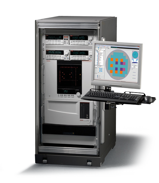
Software for High Power Device Characterization
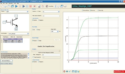
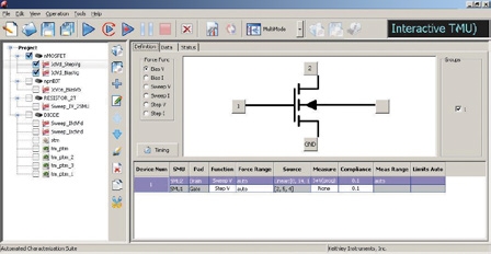
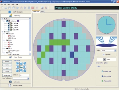
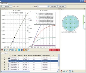
Keithley’s Automated Characterization Suite (ACS) Software combines with the high power, precision, speed, and flexibility of Keithley’s Series 2600 High Power System SourceMeter® SMU instruments and Parametric Curve Tracer configurations to create a complete environment for high power semiconductor component characterization. Depending on your application, choose from ACS Basic Edition for single device testing or ACS Standard Edition for wafer-level, multi-DUT test automation or reliability analysis.
ACS Basic Edition for Semiconductor Component and Discrete Devices
- Designed for discrete devices such as mosfets, BJTs, IGBTs, diodes, resistors, etc.
- Rich set of test libraries for fast and easy test setup without programming
- Built-in analysis tools for extracting parametric data
- Includes both interactive, real-time trace mode and parametric mode
ACS Standard Edition for Characterization, Parametric Testing, Reliability Test, and Die Sort
- Supports a wide array of instruments and probers
- Develop and execute tests at the device, site, wafer, and cassette level
- Supports multiple SourceMeter® source

| Feature | 2651A / 2657A High Current / High Voltage |
2634B / 2635B / 2636B Low Current |
2602B / 2612B Dual Channel |
2601B / 2611B Single Channel |
2604B / 2614B Dual Channel Benchtop |
| # of Channels | 1 (optional expansion to 32 via TSP-Link®) | 1 – 2 (optional expansion to 64 via TSP Link for 2635B/2363B) |
2 (optional expansion to 64 via TSP-Link) |
1 (optional expansion to 32 via TSP-Link) |
2 |
| Current Max / Min | 2651A: 50A pulse/100fA 2657A: 120mA/1fA |
2634B: 10A pulse/1fA 2636B, 2635B: 10A pulse/0.1fA |
10A pulse/100fA | 10A pulse/100fA | 10A pulse/100 fA |
| Voltage Max / Min | 2651A: 40V/100nV 2657A: 3,000V/100nV |
200V/100nV | 40V/100nV for 2602B 200V/100nV for 2612B |
40V/100nV for 2601B 200V/100nV for 2611B |
40V/100nV for 2604B 200V/100nV for 2614B |
| System-Level Automation |
Digital l/O, TSP-Link, Contact Check |
Digital l/O, TSP-Link, Contact Check (not available on 2634B) |
Digital l/O, TSP-Link, Contact Check |
Digital l/O, TSP-Link, Contact Check |
N/A |
| Max readings / sec | 38,500 1µSec/pt.,18-bit digitizer |
20,000 | 20,000 | 20,000 | 20,000 |
| Computer Interface | GPIB, LAN (LXI), RS-232 | GPIB, LAN (LXI), RS-232, USB | GPIB, LAN (LXI), RS-232, USB | GPIB, LAN (LXI), RS-232, USB | GPIB, LAN (LXI), RS-232, USB |
| Connectors/Cabling | 2651A: Screw terminal, adaptors for banana 2657A: HV triax, SHV |
Triax | Screw terminal, adaptors for banana or triax |
Screw terminal, adaptors for banana or triax |
Screw terminal, adaptors for banana or triax |
| Feature | 6430 Low I SourceMeter | 2430 High Power SourceMeter Instrument | 2410 High V SourceMeter Instrument | 2420 / 2425 / 2440 High I SourceMeter Instruments | 2400 / 2401 Low Power SourceMeter Instruments |
| Current Max / Min | 105mA / 10aA | 10.5A pulse / 100pA | 1.05A / 10pA | 5.25A/ 100pA | 1.05A / 10pA |
| Voltage Max / Min | 200V / 1uV | 200V / 1uV | 1100V / 1uV | 100V / 1uV | 200V / 1uV |
| Power | 2W | 1100W | 22W | 110W | 22W |
| Max readings / sec | 256 | 2,000 | 2,000 | 2,000 | 2,000 |
| Interface | GPIB, RS-232, Digital I/O, Trigger Link Trigger Bus | GPIB, RS-232, Digital I/O, Trigger Link Trigger Bus | GPIB, RS-232, Digital I/O, Trigger Link Trigger Bus | GPIB, RS-232, Digital I/O, Trigger Link Trigger Bus | GPIB, RS-232, Digital I/O, Trigger Link Trigger Bus |
| Connectors | Triax | Banana (front / rear) | Banana (front / rear) | Banana (front / rear) | Banana (front / rear) |
|
|
|
|||||||
| Model | 2600-PCT-1 | 2600-PCT-2 | 2600-PCT-3 | 2600-PCT-4 | 4200-PCT-2 | 4200-PCT-3 | 4200-PCT-4 | |
| Type | Entry Level | High Current | High Voltage | High Current and Voltage | High Current + C-V | High Voltage + C-V | High Current and Voltage + C-V | |
| Collector/Drain Supply | Collector/ Drain Supply High Voltage Mode | 200V/10A | 200V/10A | 3KV/120mA | 3KV/120mA | 200V/1A | 3KV/120mA | 3KV/120mA |
| High Current Mode | 200V/10A | 40V/50A | 200V/10A | 40V/50A | 40V/50A | 200V/1A | 200V/1A | |
| Step Generator (Base/Gate supply) | 200V/10A | 200V/10A | 200V/10A | 200V/10A | 200V/1A | 200V/1A | 200V/1A | |
| Typical Applications | Incoming I ction, FA, QA, Reliability, Design Qual, Product Dev. | Incoming Inspection, FA, QA, Reliability, Design Qual, Product Dev. | Incoming Inspection, FA, QA, Reliability, Design Qual, Product Dev. | Incoming Inspection, FA, QA, Reliability, Design Qual, Product Dev | Data Sheet Generation, Modeling, General Characterization | Data Sheet Generation, Modeling, General Characterization | Data Sheet Generation, Modeling, General Characterization | |
| Software | ACS Basic Edition with Trace Mode and Parametric Mode, single and sequenced tests, sample power device libraries | |||||||
| Text Fixture | Model 8010 High Power Device Test Fixture supports 3KV/100A Includes TO-220, TO-247, Axial, Custom sockets,. sample demo parts (BJT, MOSFET, diode, etc.) | |||||||
Find more valuable resources at TEK.COM
Copyright © Tektronix. All rights reserved. Tektronix products are covered by U.S. and foreign patents, issued and pending. Information in this publication supersedes that in all previously published material. Specification and price change privileges reserved. TEKTRONIX and TEK are registered trademarks of Tektronix, Inc. All other trade names referenced are the service marks, trademarks or registered trademarks of their respective companies.


