お問い合わせ
ダウンロード
マニュアル、データシート、ソフトウェアなどのダウンロード:
フィードバック
Ethernet Transmitter Test Application Software
TekExpress 10GBASE-T and NBASE-T Datasheet
詳細情報
- DPO7000シリーズ
- DPO70000SX ATIパフォーマンス・オシロスコープ
- MSO/DPO70000DXシリーズ・ミックスド・シグナル/デジタル・フォスファ・オシロスコープ
- その他の ソフトウェア 情報を見る
オンラインで読む:
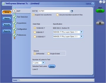
The Ethernet Transmitter Test Application automates 10GBASE-T, NBASE-T, and IEEE802.3bz (2.5G/5G) physical medium attachment (PMA) physical-layer (PHY) electrical testing to provide a fast and accurate way of testing your Ethernet designs.
Features and benefits
- Comprehensive automated solution for 2.5GBASE-T, 5GBASE-T and 10GBASE-T PHY testing
- One-button selection of multiple tests and four-channel support
- Detailed test reports with margin and statistical information aid analysis
- User-defined mode enables flexible parameter control for characterization and margin analysis
- Efficient test execution on oscilloscopes with instrument remote control
- Single instrument analysis of time- and frequency-domain measurements
- Signal acquisition and analysis support for differential probes or direct SMA cabling
Product description
Based on the TekExpress test automation framework, the Ethernet Transmitter Test Application performs all of the PMA electrical measurements as specified by the 802.3an standard, the 802.3bz standard, and the NBASE-T specification. This allows you to quickly and efficiently test Ethernet devices running at 2.5G, 5G, and 10G data rates.
To accurately make these measurements, the Tektronix TF-XGBT test fixture is also needed. The test fixture allows you to reliable and easily access the device under test (DUT) using either differential probes or matched SMA cables.

Test selection and instrument setup
Test selection is easy and straight-forward through the intuitive TekExpress workflow. Simply check the measurements you want to perform.
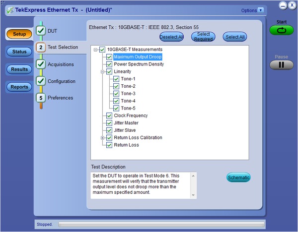
For each measurement selected, the Ethernet Transmitter application will then automatically set up and configure the oscilloscope saving time and ensuring repeatable, reliable results.
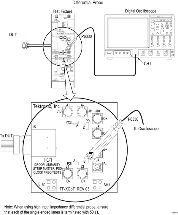
As each test is performed, the application will also show you with detailed diagrams how to properly make the needed connections.
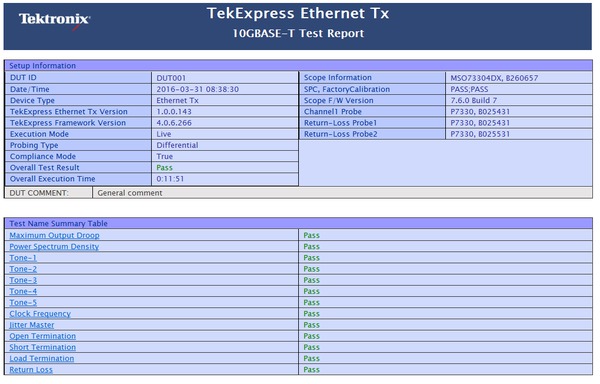
Reports
A summary report with Pass/Fail status for each test is created after the tests are complete. This report includes test configuration details, waveform plots, and margin analysis to provide more insight into your design.
Margin testing
You can also make changes to test limits and other test parameters in order to do margin analysis to see how well your device is performing.
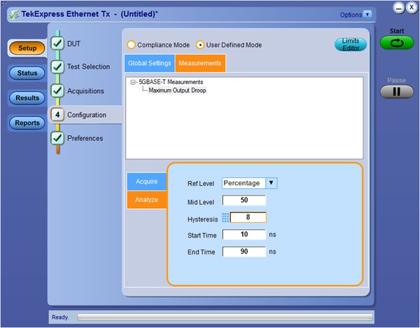
Differential single-ended acquisition support
The application allows signal acquisition and analysis with either matched-pair SMA cables or differential probes.
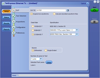
Return loss
The Ethernet Transmitter Test Application simplifies Return Loss testing and eliminates the need for a Vector Network Analyzer by using a patented oscilloscope-based measurement along with a Tektronix AWG. Calibration data for Open, Load, and Short can be stored in a file and recalled.

Complete programming interface
The programmatic interface seamlessly integrates the Ethernet Transmitter Test application with a high-level automation layer such as Visual Basic, MicrosoftNet, C#, C++, Python, or a Web application. This lets you control the state of the TekExpress application running on a local or a remote computer.
Programming examples are found in the application examples folder.
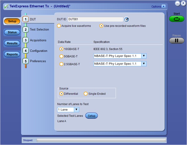
Prerecorded waveform
Prerecorded Waveform support will provide customers an option to use prerecorded waveforms when an oscilloscope is not available. This feature allows waveforms to be shared across multiple locations and removes end-user dependency from using scopes all the time.
Specifications
- 10GBASE-T Measurements
The following tests are performed per the IEEE802.3-2012 standard. The device under test (DUT) must be able to provide the test mode signals as indicated in IEEE802.3-2012 Subclause 55.5.2.
Measurement Standard reference and Test mode Maximum Output Droop IEEE802.3-2012 Subclause 55.5.3.1 Transmitter Timing Jitter - Master IEEE802.3-2012 Subclause 55.5.3.3 Transmit Clock Frequency IEEE802.3-2012 Subclause 55.5.3.5 Transmitter Timing Jitter - Slave IEEE802.3-2012 Subclause 55.5.3.3 Transmitter Linearity IEEE802.3-2012 Subclause 55.5.3.2 Transmitter Power Spectral Density (PSD) and Power IEEE802.3-2012 Subclause 55.5.3.4 Return Loss IEEE802.3-2012 Subclause 55.8.2.1
- 2.5GBASE-T and 5GBASE-T Measurements (requires NBASET option)
The following tests are performed per IEEE802.3bz/D3.3 draft standard. The device under test (DUT) must be able to provide the test mode signals as indicated in IEEE802.3bz/D3.3 Subclause 126.5.2.
Measurement Test mode Maximum Output Droop IEEE80.bz/D3.3 Subclause 126.5.3.1 Transmitter Timing Jitter - Master IEEE80.bz/D3.3 Subclause 126.5.3.3 Transmit Clock Frequency IEEE80.bz/D3.3 Subclause 126.5.3.5 Transmitter Timing Jitter - Slave IEEE80.bz/D3.3 Subclause 126.5.3.3 Transmitter Nonlinear Distortion IEEE80.bz/D3.3 Subclause 126.5.3.2 Transmitter Power Spectral Density (PSD) and Power IEEE80.bz/D3.3 Subclause 126.5.3.4 Return Loss IEEE80.bz/D3.3 Subclause 126.8.2.1
- NBASE-T Measurements (requires NBASET option)
The following tests are performed per the NBASE-T Physical Layer Specification. The device under test (DUT) must be able to provide the test mode signals as indicated in NBASE-T Physical Layer Specification version 1.1 Subclause 2.9.
Measurement Test mode Maximum Output Droop Subclause 55.5.3.1, Test Mode 6 Transmitter Timing Jitter - Master Subclause 55.5.3.3, Test Mode 2 Transmit Clock Frequency Subclause 55.5.3.5, Test Mode 2 Transmitter Timing Jitter - Slave Subclause 55.5.3.3, Test Mode 1 and Mode 3 Transmitter Nonlinear Distortion Subclause 55.5.3.2, Test Mode 4, Tones 1-5 Transmitter Power Spectral Density (PSD) and Power Subclause 55.5.3.4, Test Mode 5 Return Loss Subclause 55.8.2.1, Test Mode 5
Ordering information
- 10GBASE-T
- New instrument orders
Product Option Description DPO/MSO70000 XGBT2 TekExpress Automated 10GBASE-T Solution DPO7354C XGBT2 TekExpress Automated 10GBASE-T Solution - For users with existing DPO/DSA/MS070000C/D/DX/SX Series Oscilloscope or DPO7354C Oscilloscope
Product Option Description DPO-UP XGBT2 TekExpress Automated 10GBASE-T Solution Upgrade DPOFL-XGBT2 - TekExpress Automated 10BASE-T Solution - Floating License
DPOFT-XGBT2 - TekExpress Automated 10BASE-T Solution - Floating Trial
- NBASE-T and IEEE802.3bz
- New instrument orders
Product Option Description DPO/MSO70000 NBASET TekExpress Automated NBASE-T and IEEE802.3bz Solution DPO7354C NBASET TekExpress Automated NBASE-T and IEEE802.3bz Solution DPO7254C NBASET TekExpress Automated NBASE-T and IEEE802.3bz Solution - For users with existing DPO/DSA/MSO70000C/D/DX/SX Series Oscilloscope or DPO7254C/DPO7354C Oscilloscope
Product Option Description DPO-UP NBASET TekExpress Automated NBASE-T and IEEE802.3bz Solution Upgrade DPOFL-XGBT2 - TekExpress Automated NBASE-T and IEEE802.3bz Solution - Floating License
DPOFT-XGBT2 - TekExpress Automated NBASE-T and IEEE802.3bz Solution - Floating Trial
Supported probes
| Oscilloscopes | For Droop, PSD, Linearity, Clock Frequency, Jitter-Master, and Jitter-Slave measurements | For Return Loss measurement |
|---|---|---|
| DPO7254C/DPO7354C | P6300 - Minimum of one and maximum of four required | P6300 - Minimum of two required |
| TDP3500 - Minimum of one and maximum of four required | TDP3500 - Minimum of two required | |
| SMA Cables - Minimum of two required | NA | |
| DPO/DSA/MSO70000C/D/DX/SX Series | P6300 - Minimum of one and maximum of four required | P6300 - Minimum of two required |
| P7330, P7340A, P7350, P7360A, P7380A, and P7313 - Minimum of one and maximum of four required | P7330, P7340A, P7350, P7360A, P7380A, and P7313 - Minimum of two required | |
| TriMode Probes (P7504, P7506, P7508, P7513A, P7516, and P7520) - Minimum of one and maximum of four required | TriMode Probes (P7504, P7506, P7508, P7513A, P7516, and P7520) - Minimum of two required | |
| P7350SMA, P7380SMA, and P7313SMA - Minimum of one and maximum of four required | NA | |
| SMA Cables - Minimum of two required | NA |
Oscilloscope compatibility
| 10GBASE-T | Recommended bandwidth |
|---|---|
| DPO7354C | 3.5 GHz |
| DPO/DSA/MSO70000C/D/DX/SX Series | ≥ 4 GHz |
| NBASE-T and IEEE802.3bz (2.5G and 5G) | Recommended bandwidth |
|---|---|
| DPO7000C | ≥ 2.5 GHz |
| DPO/DSA/MSO70000C/D/DX/SX Series | ≥ 4 GHz |
AWG compatibility (for Return Loss Measurements)
An AWG7122C is required to perform return loss measurements at all data rates.
IEEE 2.5GBASE-T Transmitter Nonlinear Distortion Test (Section 126.5.3.2)
When performing this test, the IEEE specification requires a 45 MHz sine wave to be injected. This is only required for 2.5GBASE-T. It is not required for 5GBASE-T. Supported signal sources are:
- AWG5202 with option 250, 2HV and 2DC is recommended for NBaseT (2.5G/5G/10G) compliance testing.
The recommended power splitter is: PSPL5331.
TF-XGbt 10GBASE-T, NBASE-T, and IEEE802.3bz Transmitter Electrical test fixture
The TF-XGbt test fixture is required to perform all measurements and is designed to meet the test fixture requirements in each of the applicable specifications/standards.
| TF-XGbt contains | Quantity | Description |
|---|---|---|
| Test fixture main board | 1 | Main test fixture consists of 3 sections, namely TC1, TC2, and TC3 |
| Test fixture main board | 1 | Test Fixture TC1: For Droop, Transmitter Timing Jitter - Master, Transmit Clock Frequency, Transmitter Linearity, Transmitter Power Spectral Density (PSD), and Power Level Compliance test measurements Note: Includes SMA Male-to-Female Adapter × 8 and 50 Ω SMA Terminator × 8 mounted on the SMA connectors |
| Test Fixture TC2: Transmitter Timing Jitter – Slave compliance test measurement Note: Includes SMA Male-to-Female Adapter × 2 mounted on the SMA connectors | ||
| Test Fixture TC3: Return Loss compliance test measurement Note: Includes SMA Male-to-Female Adapter × 2 mounted on the SMA connectors | ||
| Test fixture calibration board | 1 | Test Fixture TC3A: For Return Loss calibration |
| RJ45 patch cord | 2 | 0.08 meter, shielded RJ45 cable to connect the test fixture to the Return Loss calibration board and device under test |


