

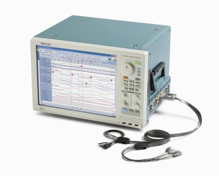
Tektronix recently introduced the TLA6400, a performance leap in the world of value-priced monolithic bench-top logic analyzers. Performance like this used to require more expensive card-modular systems, more suitable to ASIC designers than FPGA programmers or general purpose users. However, with faster parallel bus signals (such as new high-speed COTS ADC’s and DDR memory), many designers find themselves needing performance logic analyzer specifications at budget-friendly prices. While a high-end performance logic analyzer can cost over $100k, the TLA6400 starts at around $13k.
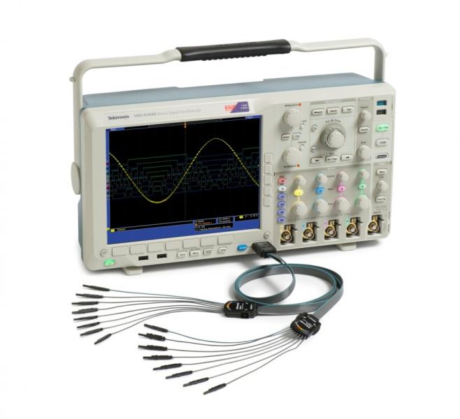
All of that being said, many engineers think $13k is still too high, noting that there are now mixed-signal oscilloscopes (MSO) that have 16 channels of digital inputs, such as the Tektronix MSO4000 series. In fact, for just a few thousand dollars, even the Tektronix MSO2000 series can provide 16 digital channels of input with sample rates up to 1 GS/s. Some people call these “oscilloscopes with built-in logic analyzers,” a description I often correct because it really isn’t accurate.
There are also small USB devices that cost less than $1,000 which call themselves logic analyzers, such as the LeCroy LogicStudio. Often these devices hook up to a PC and offer from 16 to sometimes over 50 input channels, along with a PC interface for control. Just do a Google search for “USB Logic Analyzer”. There are dozens of various options out there from many different manufacturers.

What makes a true logic analyzer different from these little USB devices or a mixed-signal oscilloscope? Also, why does a true logic analyzer normally have 4 clock rates listed? The Tektronix TLA6400 for instance specifies 667 MHz, 1333 Mb/s, 3.2 GHz, and 25 GHz as max speeds, but what do these mean?
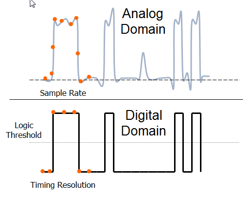
We can start with the easy specifications, but it will get more involved as we dive deeper. On a simple level, a logic analyzer is just a 1-bit oscilloscope. Instead of digitizing the whole waveform, the logic analyzer uses a single user-defined threshold voltage as a comparator. The signal is either high or low, 1 or 0. If a signal doesn’t reach the threshold, it is recorded as a 0, and if a signal goes above the threshold, it is a 1.
Unlike an MSO or a USB based logic analyzer, a logic analyzer can have over 100 inputs. It also has deeper memory. Many USB based products have less than 100k of memory, whereas a logic analyzer can have over 50 MB of memory. Also, a true logic analyzer typically can acquire at a faster rate. Most USB-based logic analyzers or MSO products go to 1 GS/s, but a logic analyzer like the Tektronix TLA6400 can provide timing resolution to 3.2 GS/s, and high-speed timing to 25 GS/s.
So a true logic analyzer has more channels, deeper memory, and faster timing. But what makes it truly distinct? The Tektronix MSO70000 series mixed-signal oscilloscope has 12.5 GS timing and 125 MB of memory, exceeding the timing and memory specifications of some logic analyzers like the Agilent 16800A, but it is still not a true logic analyzer.
The key to understanding the difference is in how the data is acquired. Most MSO or USB based products operate asynchronous to the signal under test. On a true logic analyzer, this mode is called timing, asynchronous, or internal mode. In this mode, a logic analyzer’s timebase operates like an oscilloscope. It takes a sample at the clock rate consistently, and requires that the signal be oversampled to get accurate timing, just like an oscilloscope. The sample is still a 1 or a 0, but it is taken with an internal clock that must be greater than two times faster than the signals being analyzed.
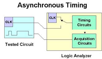
However, the real power of a logic analyzer is in its ability to clock the inputs synchronous to the data being measured, by using an explicitly measured external clock line on the device under test. This mode on a true logic analyzer is called state, synchronous, or external mode. While some MSO’s (like the Tektronix MSO4000 and MSO5000 series) can do a synchronous parallel bus decode, they cannot acquire synchronously. They must take asynchronous, oversampled data and then post-process it using a clock that was also acquired asynchronously.
The advantages of synchronous capture are many, but the most significant is that your logic analyzer will see a true picture of the digital state of your system as your system itself sees it. Listing views and even disassembly of bus transactions like DDR rely on the data in the logic analyzer being clocked from the system clock under test. You also don’t waste memory with oversampling because the data is only clocked with the logic analyzer. Logic analyzers also support compound clocks, where multiple clock lines (and qualifiers) can be used to define a valid clock signal.
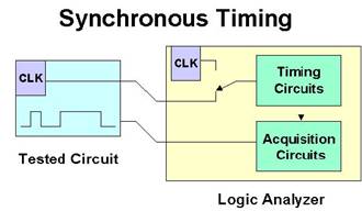
Some more advanced logic analyzers also permit time stamps to be put on the data as it is collected similar to asynchronous mode, but the data itself is only collected and stored on the clock.
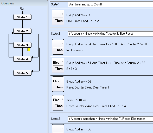
Logic analyzers also feature advanced trigger state machines. Where an oscilloscope, MSO, or USB-based logic analyzer can look for a single logic state and trigger (sometimes with a simple second stage event), a logic analyzer can follow an elaborate state machine. For instance, it can look for Address A to occur 5 times followed by Address B within a time period of 100 ms in order to trigger. Each state can contain if-then-else clauses, with loops, jumps, counters, and timers. In the case of the Tektronix TLA6400, there can be up to 16 states with 16 nested if-then-else conditions per state. All of these trigger recognizers run at the stated clock speed as will be explained below.
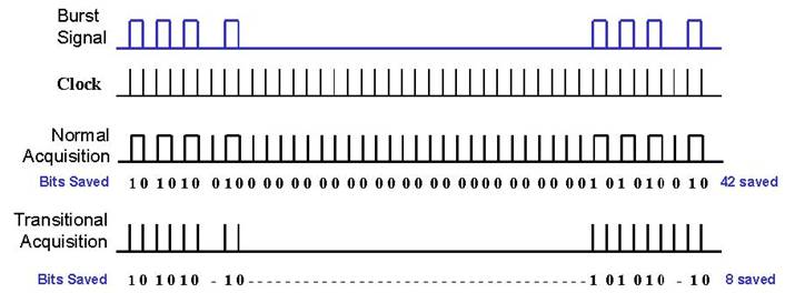
Logic analyzers also have the ability to perform a task called Transitional or Conditional Storage. In this mode, the logic analyzer doesn’t store data if the storage condition isn’t met. For instance, the analyzer can be set to only store if a data line has transitions, so it does not store data if nothing on a particular line has changed. This is useful for bursty data buses with significant amounts of dead-time. Alternatively, it can be set to store only when a particular data word (such as an address bus) is set. A logic analyzer in this mode can capture minutes or hours of seamless data of interest.
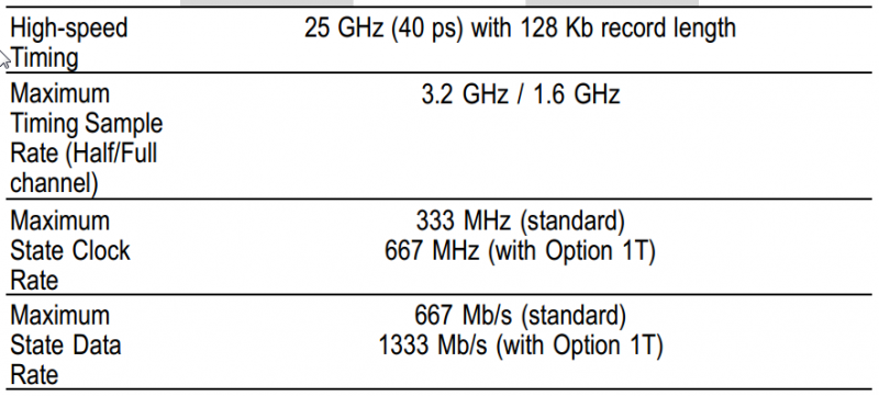
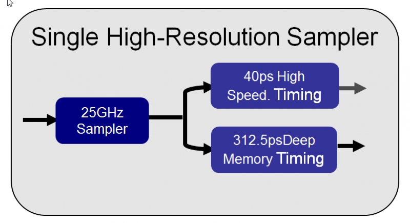
As for specifications, what do those numbers mean on a Tektronix TLA6400? The first number, 25 GHz indicates high-speed timing, called MagniVu by Tektronix. In the TLA6400, all data is sampled by the 25 GS/s sampler, and 128 kB of that data is held for MagniVu while the rest is decimated for deep memory timing. As a result, the high-speed timing granularity is 40ps. The decimation rate for deep memory is the next number, 3.2 GHz, or 312.5 ps between points. This particular specification is a half-channel specification (with half the channels turned off). With all of the channels turned on, the state clock is at 1.6 GHz. This number indicates the speed at which the deep memory on the logic analyzer can be timestamped.
So if a system clock runs at 1 GHz, can a TLA6400 acquire it? The answer is a qualified yes, bearing in mind that a key distinction of a logic analyzer is its trigger system and memory controllers. And these features don’t operate at a full 3.2 GHz. Hence, the next number, 667 MHz, is the speed at which the trigger state machine can process the clock in real-time. If the system clock runs faster, the trigger recognizers will not keep up.
The fourth number, 1333 Mb/s, is the speed of the trigger state machine on a double-data rate signal (DDR), when the clock is on the rising and falling edge. Why is this specified since it is just two times the maximum clock frequency? The answer is because on some older logic analyzers, the hardware to handle DDR signals is a lower base frequency, so the DDR rate is not always twice the maximum single edge clock rate. For instance, an Agilent 16800A can trigger on a 450 MHz state clock single edge, but only 500 Mb/s acquisitions for DDR.
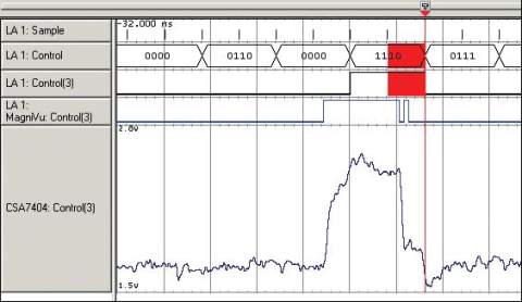
Another powerful feature on a logic analyzer is the suite of tools for analyzing signal integrity issues. For instance, in asynchronous mode, a poor termination or reflection can cause two crossings of a threshold between sample points. This condition is known as a glitch, and some logic analyzers like the TLA6400 can not only trigger on it, but mark the spot in memory where it occurred. In synchronous mode, the logic analyzer can monitor, trigger, and mark locations that setup and hold timing was violated. The Tektronix TLA6400 even has the ability to route up to four signals out of an analog mux to an oscilloscope so that they can be digitized and viewed in the analog domain. The image below shows a glitch in regular timing display (marked only in red), MagniVu display, and analog representation from the analog mux.
A logic analyzer is a lot more than a multi-channel 1-bit oscilloscope. While the MSO or USB-based logic analyzer provide digital inputs, most lack the synchronous-state mode clock, complex trigger state machine, conditional storage, and tools for analyzing signal integrity. Hence, the stand-alone logic analyzer still provides a compelling and powerful toolset to complement your bench and speed time to answer.


