Probing a circuit always has some impact on signals. Probe loading changes the signal being probed and can cause measurement problems or can even cause a circuit to perform differently. Reducing capacitive loading can help minimize these effects. In this application note, you’ll learn how low capacitance probes can improve your measurements.
Below we outline some of the major advantages and disadvantages of traditional passive probes and how Tektronix products such as the TPP1000, TPP0500B, & TPP0250 can overcome many of the challenges associated with traditional passive probes.

Above we can see the primary pros and cons of traditional passive probes as it relates to circuit probing.
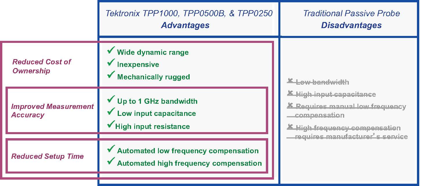
Above we see the advantages that Tektronix low capacitance probes offer when compared directly to other traditional probes offered by competitors.
An Introduction to Minimizing Probe Loading
This application note describes how the high-bandwidth, low-capacitance passive voltage probes from Tektronix reduce the oscilloscope user's total cost of ownership, improve performance and measurement accuracy, and save setup time. Passive voltage probes that ship standard with most oscilloscopes provide a low cost, general purpose probing solution. Generally, these probes lack the performance of an active voltage probe but provide the ruggedness and wide dynamic range suitable for visualizing signals. Table 1 describes the advantages and disadvantages of traditional passive probe solutions.
The TPP1000, TPP0500B, and TPP0250 redefine performance in the passive probe category, with specifications previously unrealized in this class. These probes are designed for use with Tektronix 4, 5 and 6 Series MSO, 3 Series MDO, MDO3000, MDO4000, and MSO/DPO5000 Series oscilloscopes.
This level of performance is obtained through the combination of circuitry within the oscilloscope and the probe. The improvements in bandwidth, input capacitance and automated probe compensation turn traditional passive probing disadvantages into advantages as shown in Table 2.
This application note will describe in more detail:
Reduced Cost of Ownership
The limitations of standard passive probes, especially on 1 GHz systems, force the user to purchase active probes which significantly increases the overall investment cost. TPP1000, TPP0500B, and TPP0250 probes bridge the gap between traditional passive probes and higher performance, higher cost active probes. With industry leading passive probe specifications and automated low and high frequency compensation, the TPP1000, TPP0500B, and TPP0250 reduce the user's total cost of ownership and make the oscilloscope investment even more valuable.
Improved Measurement Accuracy
Several factors affect how well a probe can deliver a signal to the oscilloscope, and the user should consider:
 |
Performance Specifications
General purpose passive probes favor ruggedness over performance. This trade-off has long sufficed because these probes have been mainly used to visualize low-speed signals. This trade-off has also been made because of the significant design challenges in creating a probe that is rugged, high performance, and capable of measuring hundreds of volts.
Active probes typically start at 1 GHz bandwidth, measure less than 10 V (though some Tektronix probes go up to 40 V), and lack the robustness of a passive probe. Passive probes are typically 500 MHz or less, measure hundreds of volts, and are rugged. The TPP1000, TPP0500B, and TPP0250 are the only probes that offer performance, wide dynamic range and the ruggedness required for daily use.
The banner performance specification for oscilloscopes and probes is bandwidth. Bandwidth is a measure of frequency response, and oscilloscopes are primarily time-domain instruments. The data displayed on an oscilloscope is a graph of amplitude versus time and differences that look small in the frequency domain can have a big impact in the time domain.
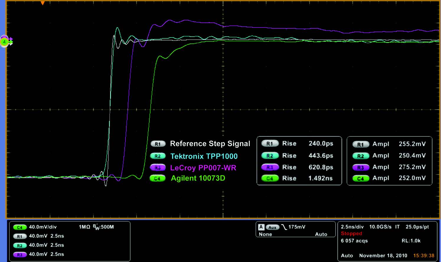
Most oscilloscope users need an oscilloscope and probe with excellent step response because it is a better indication of what the output of the probe will look like on the oscilloscope display. To properly show the system step response, a fast, clean step signal is injected into the measurement system. Probe rise time evaluation requires a signal with a faster edge rate than the probe is capable of. Consider the screen shots in Figure 1 which compare the rise time of the TPP1000 probe from Tektronix and passive probes that ship standard from LeCroy and Agilent.
Each probe was attached to the same test fixture utilizing the probe's short ground spring for optimum performance. As shown in the screen shots above, a fast, clean step signal with a 240 ps rise time was established as the reference to compare the probe's step response against. The reference signal is identified as R1 and is the white trace.
The TPP1000 from Tektronix has the fastest rise time (443.6 ps), has a waveform with the same amplitude and shape as the reference with minor overshoot. The TPP1000 is the passive probe most capable of capturing signals with fast edge rates.
|
 |
Low Input Capacitance at the Probe Tip
Because standard passive probes are primarily used to visualize signals, most users attach a long probe ground lead to a ground connection. A long ground lead makes it easier to move the probe around the board to various test points without having to attach and re-attach the ground connection.
Short ground springs provide the best performance but ground may not always be within the spring's range. Long ground leads, those that are 6" or longer, make obtaining a ground connection easier, but long ground leads reduce performance due to the added inductance.
As the length of the ground lead increases, the inductance added into the measurement increases. Inductance and capacitance are related to frequency and as the probe's inductance and capacitance increases, the probe's performance decreases. For example, a probe with a 6" ground lead attached is capable of greater performance and accuracy than the same probe with a 12" ground lead attached.
To address the performance issues caused by ground leads, the options are to reduce the inductance by using shorter ground leads or to find a probe with lower input capacitance. The TPP1000, TPP0500B, and TPP0250 offer < 4 pF input capacitance at the probe tip compared to 9.5 pF input capacitance offered in other standard passive probe offerings.
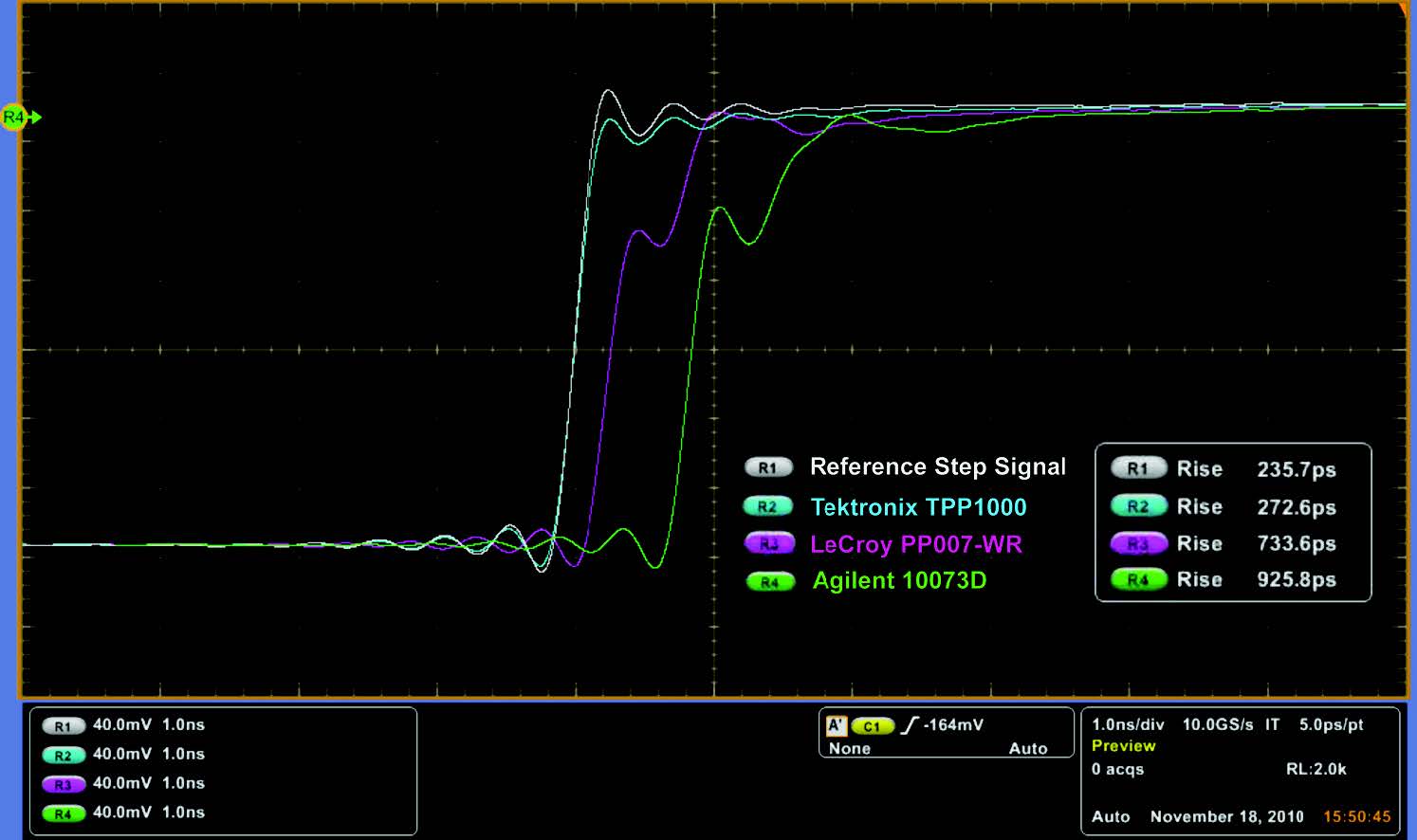
With these Tektronix passive probes, users can attach longer ground leads without suffering the signal degradation from probes with higher input capacitance. Figure 2 shows the step responses of Tektronix, LeCroy and Agilent standard passive probes with a long probe ground lead attached.
The performance impact of adding long probe ground leads is substantial. The probe's rise time decreases and the output signal has ringing, increased overshoot, and greater amplitude inaccuracy. The TPP1000, TPP0500B, and TPP0250 offer users the convenience of using longer probe grounds when visualizing signals without suffering significant loss in performance and accuracy.
 |
Probe Loading 101
A passive probe's input capacitance and input resistance at the probe tip specification is important because it affects the circuit under test. When an external device, such as a probe is attached to a test point, it will appear as an additional load on the signal source drawing current from the circuit. This loading, or signal current draw, changes the operation of the circuitry behind the test point and changes the signal seen at the test point.
The ideal probe would have infinite impedance, but this is not possible because a probe must draw some small amount of signal current in order to develop a signal voltage at the oscilloscope input. A probe will always induce some signal source loading; the challenge is to keep this as low as possible.
The loading of greatest concern is caused by the capacitance at the probe tip. For low frequencies, this capacitance has a reactance that is very high and has little or no effect on the circuit under test. As frequency increases, the capacitive reactance decreases and at higher frequencies, the capacitive loading is higher.
Capacitive loading affects the bandwidth and rise time characteristics of the measurement system by reducing bandwidth and increasing rise time. The TPP1000, TPP0500B, and TPP0250 offer significantly lower input capacitance than any existing high impedance general purpose passive probe. The input capacitance at the probe tip for these probes is < 4 pF, notably lower than the ≥ 9.5 pF offered in non-Tektronix probes. Figure 3 shows the probe loading of the Tektronix TPP1000 to standard offerings from LeCroy and Agilent.
The white trace is the input signal waveform and the other traces show how the reference waveform changes when probes are attached to the test point. It is important to remember that the waveforms shown in this image are not the output of the probe, but they show how the probe affects the signal at the test point.
The blue trace shows the minimal loading impact of the TPP1000 on the source signal as it closely matches the reference waveform and has minimal impact on rise time. The effects of the additional input capacitance of the non-Tektronix probes have an impact on performance and accuracy. As stated above, capacitance reactance decreases at higher frequencies, and the capacitive loading has a greater impact as frequency increases.
A higher capacitance probe will have greater loading at higher frequencies which explains the rounded front corner on the LeCroy and Agilent loading signals; the front edge is where the high frequency content of the square wave is located. When probing faster signals, non-Tektronix probes will more significantly distort the source signal and create measurement inaccuracy.
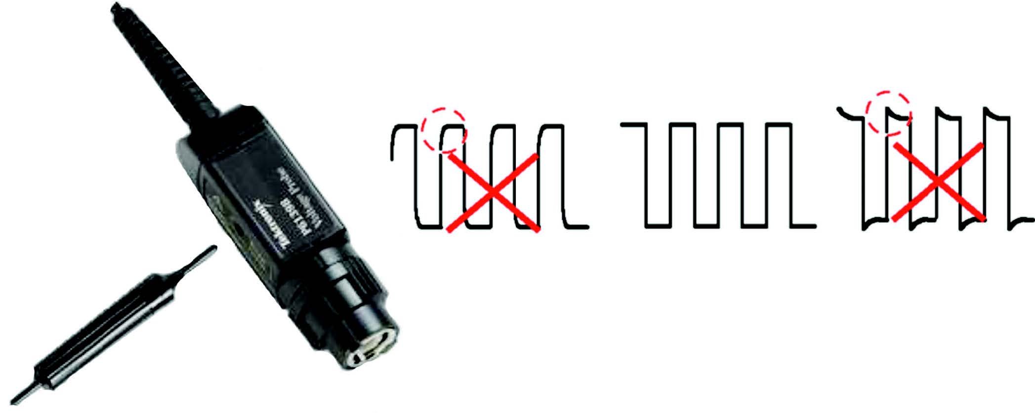
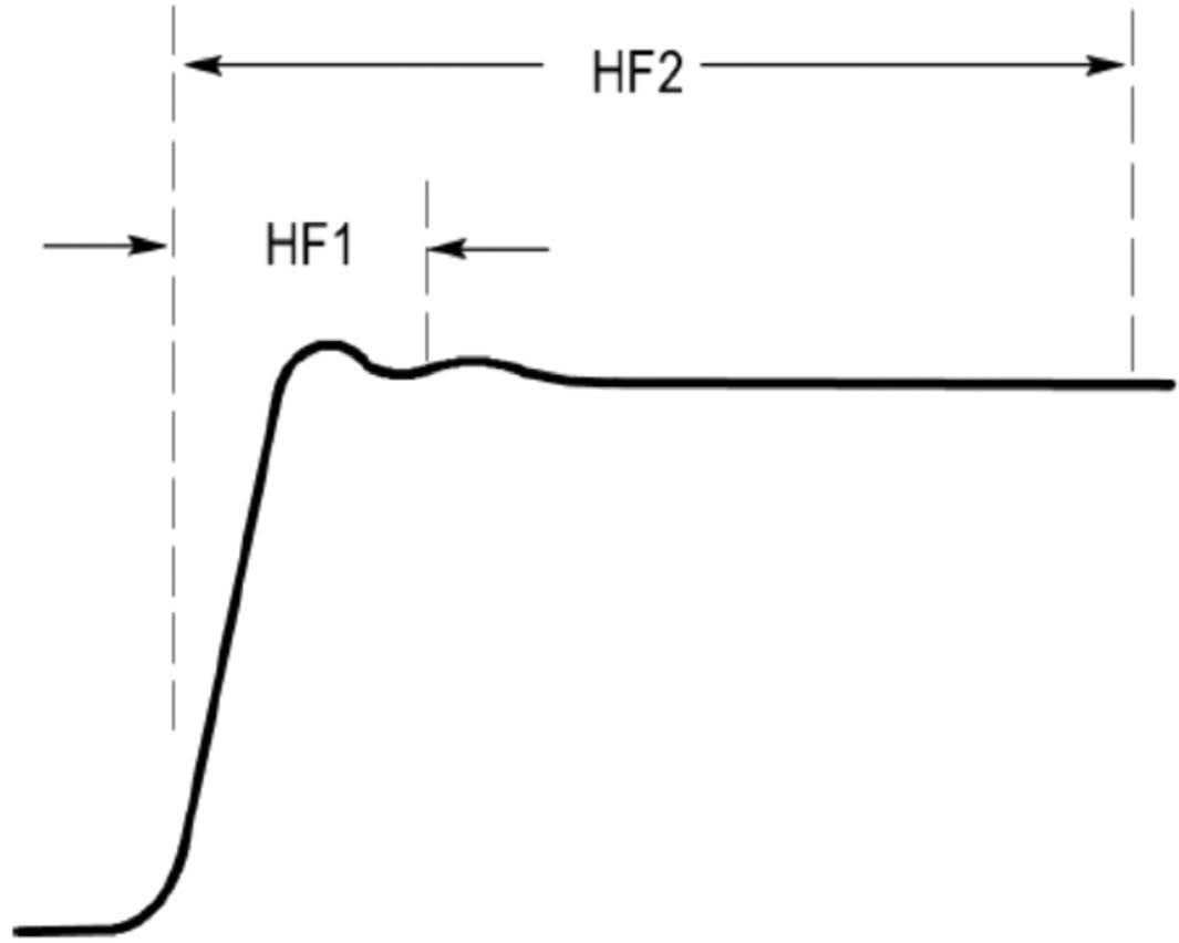
Figure 5. High Frequency Probe Compensation.
Reduced Setup Time
Due to variations in the probe and oscilloscope input characteristics, general purpose passive probes require low frequency compensation. The user may not be aware that low frequency compensation is required, may forget about this procedure, or may forgo low frequency compensation to save time. As shown in Figure 4, the probe output has to be compensated using an adjustment tool until the response is flat as shown in the "Properly compensated" example below.
While low frequency compensation is a necessary and a common user adjustment on all passive probes, high frequency compensation typically requires the adjustment to be performed by the manufacturer's service department.
High frequency compensation adjustment points are typically not user accessible and may require the user to damage
outer labels on the compensation box to obtain access. This compensation may also require special equipment such as a calibration generator and special probe adapters to make the necessary adjustments. High frequency compensation corrects aberrations to leading edge and long term flatness as shown in Figure 5.
 |
Figure 6. Automated Low and High Frequency Probe Compensation.
The TPP1000, TPP0500B, and TPP0250 when connected to a compatible Tektronix oscilloscope are capable of automated low frequency and high frequency compensation. It takes less time to compensate a TPP1000, TPP0500B, and TPP0250 for both high and low frequency compensation than the time required to manually adjust a standard passive probe for low frequency compensation.
With a TPP1000, TPP0500B, and TPP0250, the probes may be easily compensated when first attaching a probe to a channel by holding the probe tip and ground to the oscilloscope's PROBE COMP pins and selecting "Compensate Probe for <channel number>". Example selections are shown in Figure 6. The procedure takes less than five seconds and the compensation results are stored in the oscilloscope in case the probe is removed and re-attached. The oscilloscope is capable of storing results for multiple probes for each channel.
Pogo Pin
The TPP1000, TPP0500B, and TPP0250 ship standard with replaceable rigid tip and pogo pin cartridges. The pogo pin tip is spring loaded and it takes less compression on the pin to establish good electrical contact which means that the user does not have to press down as hard on the probe tip. The force required to make good contact is an important aspect for a couple of reasons. First, the user does not have to focus on keeping his hand in the right position while operating the oscilloscope.
With the pogo pin installed, the probe maintains constant pressure and provides the user some give in the pressure required to make good contact and is more comfortable when the probe is being used to visualize signals. Also, users have a tendency to push down harder on the probe when good contact is not made or if the signal does not appear on the oscilloscope as expected.This increase in force may cause the probe to inadvertently slip off the test point and make inadvertent contact with adjacent signals which could damage the test equipment or the device under test.
MMCX Cartridge
The TPP1000 and TPP0500B have available an optional tip that dramatically decreases stray EMI coupling, virtually eliminates ground lead inductance, and attaches securely to a test point.
All of these benefits are delivered through an industry standard RF connector called MMCX. MMCX is a cheap, readily available, industry standard connector commonly used in RF applications. The MMCX cartridges screw into the TPP1000 or TPP0500B probe head.
Conclusion
The TPP1000, TPP0500B, and TPP0250 redefine performance in the passive probe product category, with specifications previously unrealized in this product class, turning traditional passive probing disadvantages into advantages. These probes bridge the gap between general purpose passive probes and higher cost active probes by providing the best of both technologies: high performance; low cost; capable of measuring dynamic range in the hundreds of volts; low input capacitance; and the ruggedness required for daily use.
With industry leading passive probe specifications and automated compensation, the TPP1000, TPP0500B, and TPP0250 reduce the user's total cost of ownership and add tremendous value to the oscilloscope investment.
Copyright © Tektronix. All rights reserved. Tektronix products are covered by U.S. and foreign patents, issued and pending. Information in this publication supersedes that in all previously published material. Specification and price change privileges reserved. TEKTRONIX and TEK are registered trademarks of Tektronix, Inc. All other trade names referenced are the service marks, trademarks or registered trademarks of their respective companies. 06/19 EA 51W-26294-6

