연락처
텍트로닉스 담당자와 실시간 상담 6:00am-4:30pm PST에 이용 가능
전화
전화 문의
9:00am-6:00PM KST에 이용 가능
다운로드
매뉴얼, 데이터 시트, 소프트웨어 등을 다운로드할 수 있습니다.
피드백
Advanced Power Measurement and Analysis Software
DPOPWR Datasheet
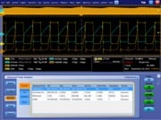
DPOPWR, Advanced Power Measurement and Analysis software, allows power supply designers to configure multiple measurements with custom defined settings, measure and analyze power dissipation in switching devices, and measure and analyze magnetic parameters in a single acquisition. The addition of new measurements such as Inrush current, Capacitance, and Reactive power provides more insight into the input / output characterization of power supplies. Designers who otherwise spend a lot of time manually analyzing power dissipations per cycle can now, with the Switching loss plot and the Time trend plot, measure power dissipation at all switching cycles graphically. A single .mht format with the append feature provides an easy way to generate reports that include measurements, test results, and plot images. This solution elevates your productivity to a new level and helps SMPS designers meet pre-compliance requirements.
Key performance specifications
- Switching Loss measurement computes TON, TOFF, Conduction and Total loss values and trajectory plot synchronizes with the ON and OFF States and corresponding values for each cycle or all switching cycles.
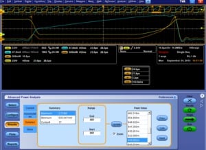
- Hi-Power Finder identifies all the peaks in the power waveform and provides interactive Detail results. It can automatically traverse between the peak values and show energy and loss values for each switching cycle.
- RDS(on) and SOA measures dynamic internal resistance and provides customizable safe operating area mask testing with linear and log scales.
- Magnetic Measurements compute total magnetic loss, inductance of core and shows a graph of the relationship between B and H.
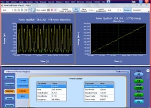
- Power Quality measurements compute THD, True Power, Apparent Power, Power Factor, Crest Factor, and Phase angle are shown in a quick view as Summary results table.
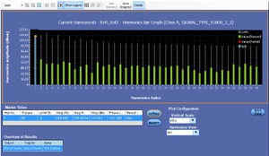
- Current Harmonics enables all pre-compliance testing to cover EN61000-3-2, EN61000-3-2 AM14, and MIL-STD-1399 (400 Hz) standards, user defined mode. Displays up to the 100th harmonic values in both table and bar graph formats.
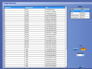
- Voltage Harmonics provide a frequency-domain view of the AC voltage, such as at the output of an inverter.
- Inrush current measurement identifies the peak currents based on configured threshold level.
- Timing analysis displays time-trend plot of the cycle-to-cycle variations in the modulated switching signal based on positive and negative pulse width, positive and negative duty cycle, frequency, and period measurements.
Key features
- New measurements such as Inrush current, Capacitance, Reactive power and Switching loss trajectory plot which provides more insight to Input/output characterization.
- Custom source Autoset for vertical and horizontal sets the oscilloscope parameters automatically, increasing your productivity and measurement repeatability.
- Automatic computation line frequency provide more accurate results for Voltage and Current Harmonics.
- Automatic detection of PFC circuit waveforms which prompts the user to use VG for noisy/ringing switching waveforms.
- Multiple measurements can be run at same time for single acquisition, providing correlated power measurements.
- Synchronization of Time trend plot with actual waveform, allowing you to observe the variation of measurements over time.
- A single .mht format with the append feature provides an easy way for you to generate reports that include measurements, test results and plot images.
- Automatic detection of probes, Auto de-gauss, AutoZero, and de-skew utilities.
- Reference waveform support helps the user to do post-analysis, now available for all measurements.
- Seamless integration of the application with the oscilloscope allows you to switch between them easily and debug more effectively.
- Global configuration features such as acquisition mode (HiRes), cursor gating, coupling and BW limits are applied uniformly across a group of measurements.
Product description
DPOPWR Advanced Power Measurement and Analysis software transforms Tektronix Windows oscilloscopes into sophisticated debug and analysis tools that quickly measure and analyze power dissipation in power supply switching devices and magnetic components.
Current harmonic Measurement helps the power supply designers to ensure pre-compliance of their designs to industry standards such as the IEC EN61000-3-2/EN61000-3-2 AM14 before investing in the official compliance testing.
DPOPWR provides several specific measurements to run in a group and characterize power supplies such as Input and Output analysis, Switching analysis, and Magnetic analysis.
Built-in Degauss and Probe deskew features enable accurate and repeatable results.
DPOPWR provides a convenient .mht formatted report which documents the test results with append feature of previous results.
DPOPWR, used with an MSO/DPO5000/B, DPO7000C or MSO/DSA/DPO70000C/DX Series oscilloscope with TxDP High Voltage differential Probes and TCP current probes, forms a complete measurement system for power supply design and test.
Magnetic component analysis
Supports the following measurements: Magnetic loss, Inductance, Maximum magnetic flux density, Permeability, Remanence flux density, Coercive force, and BH curve.
Magnetic components are an important part of any power supply system. Inductors and transformers are used as energy storage devices in both switch-mode and linear power supplies. Some power supplies also use inductors in filters at their output. Given their important role in the system, it is essential to characterize these magnetic components to determine the stability and overall efficiency of the power supply.
Inductance
Inductors exhibit increasing impedance with frequency, impeding higher frequencies more than lower frequencies. This behavior is known as inductance and is measured in units of Henries. The inductance can be measured automatically with DPOPWR.
Magnetic power loss
An analysis of magnetic power losses is essential to accurately characterize the efficiency, reliability, and performance of a switching supply. DPOPWR measures the total magnetic power loss (which includes core losses and copper losses) as shown in the following figure.

B-H plots
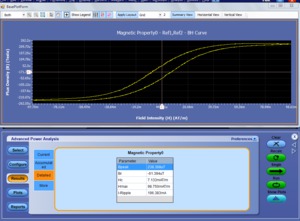
The properties of magnetic materials are described by the magnetic flux density (B), magnetic field intensity strength (H), and the magnetic permeability of a material (μ). B-H curve plots are often used to verify the saturation (or lack thereof) of the magnetic elements in a switching supply and provide a measure of the energy lost per cycle in a unit volume of core material. DPOPWR measures the voltage across the magnetic element and the current flowing through it, and plots B versus H, as shown here.
Switching component analysis
The accurate calculation and evaluation of energy loss in power supplies has become even more critical with the drive to higher power conversion efficiency and greater reliability.
Switching loss measurements
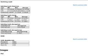
Although almost all components of a power supply contribute to energy losses, the majority of energy losses in a switch-mode power supply (SMPS) occur when the switching transistor transitions from an OFF to an ON state (turn-on loss) and vice versa (turn-off loss). By measuring the voltage drop across the switching device and the current flowing through the switching device, DPOPWR computes switching loss measurement parameters for each cycle as shown below.
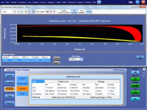
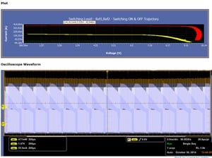
The Trajectory plot for switching loss measurements shows the trajectory of turn-on loss and turn-off loss for all switching cycles.
Active PFC offers better THD, significantly smaller size, and operates at a higher switching frequency than the 50 Hz/60 Hz line frequency. Buck, boost, flyback and other converter topologies are used in active PFC circuits. The regulated input of the DC-DC converter also demands a lower range of duty cycle from the DC-DC converter.
Hi power finder
Dynamically changing loads can cause a switching power component to exceed its voltage and current limits, and in turn, its power rating. The DPOPWR Hi Power Finder is a unique feature which analyzes the power loss in switching components, ensuring that the instantaneous power remains within the specified limits. The Hi Power Finder is shown here.
Safe operating area
The safe operating area (SOA) plot is a graphical technique for evaluating a switching device to ensure that it is not being stressed beyond its maximum specifications. SOA testing can be used to validate performance over a range of operating conditions, including load variations, temperature changes, and variations in input voltages. Limit testing can also be used with SOA plots to automate the validation. An example of an SOA plot is shown below.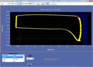
Input analysis
Power quality measurements and current harmonics are two common sets of measurements made on the input section of a power supply to analyze the effects of the power supply on the power line.
Inrush and capacitance measurement
DPOPWR provides a method to measure the peak inrush current and capacitance value for switching power supply during in-circuit operation.
Power quality
Power quality refers to a power supply's ability to function properly with the electric power that is supplied to it. These measurements help understand the effects of distortions caused by nonlinear loads, including the power supply itself. The measurements include RMS voltage and current, true and apparent power, crest factor, line frequency, and power factor, as shown here.
Current harmonics
Because a switching power supply presents a nonlinear load to the power line, the input voltage and current waveforms are not identical. Current is drawn for some part of the input cycle, causing the generation of harmonics on the input current waveform. Excessive harmonic energy can affect the operation of other equipment connected to the power line and increase the cost of delivering the electric power. Therefore, power supply designers can use the DPOPWR current harmonics measurements to assure pre-compliance of their designs to industry standards (such as IEC61000-3-2 and MIL-STD-1399) before investing in the official compliance testing. An example of the current harmonics graph display of up to 100 harmonics is shown here.
Voltage harmonics
DPOPWR Voltage harmonics measurements provide a frequency-domain view of the AC voltage, such as at the output of an inverter, as shown below.
Amplitude measurements
Amplitude measurements such as High, Low, High-low, Cycle Min, Cycle Max, and Cycle Pk-Pk help measure both Voltage and Current of the input/output circuit.
Output analysis
The ultimate goal of a DC-output power supply is to transform input power into one or more DC-output voltages. Especially for switching power supplies, the most important output measurements are line ripple, switching ripple, spectral analysis, and turn-on time.
Line-switching ripple
The quality of a power supply's DC output should be clean with minimal noise and ripple. Line ripple measures the amount of AC-output signal related to the input line frequency. Switching ripple measures the amount of AC signal related to the switching frequency. The output line ripple is usually twice the line frequency; whereas the switching ripple is typically coupled with noise and in the kHz frequency range. DPOPWR greatly simplifies the separation of line ripple from switching ripple.
Spectral analysis
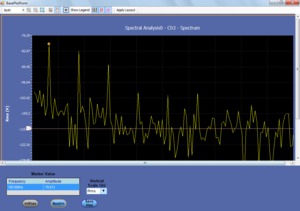
Spectral Analysis is used to analyze the frequency components that contribute to the electromagnetic interference (EMI) of the power supply. It also measures the noise/ripple at the output DC voltage frequency range. Like the oscilloscope's FFT, the DPOPWR spectral analysis displays the magnitudes of the output signal frequency components versus frequency, allowing the identification of each of the AC components, as shown here.
Turn-on time
Turn-on time is defined as the time it takes from when the power supply is turned on to when a valid, usable output is available. DPOPWR automates this measurement on up to three outputs simultaneously.
Report generation in .mht format
Data collection, archiving, and documentation are often tedious but necessary tasks in the design and development process. DPOPWR is equipped with a .mht report generation tool that makes the documentation of measurement results easy and effortless.
DPOPWR provides the ability to compile all the results of a test run into different report formats with pass/fail results for easy analysis and record keeping.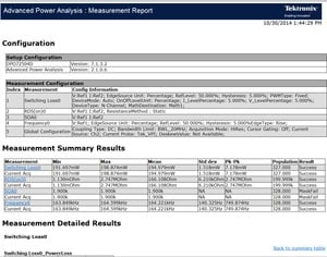
Specifications
- Switching analysis
- Switching loss, Ton, Toff, Conduction loss, Hi power finder, Safe operating area (SOA), SOA with Mask testing, RDS(ON), di/dt, dv/dt, PFC analysis.
- Magnetics
- Magnetic loss, Inductance, Maximum magnetic flux density, Permeability, Remanence flux density, Coercive force.
- Input analysis
- True power, Apparent power, Power factor, Reactive power, Crest factor, Phase angle, Inrush Current, Capacitance, THD, Voltage harmonics, Current harmonics, Pre-compliance testing for EN61000-3-2, EN61000-3-2 AM14, and MIL-STD-1399 (400 Hz) standards
- Output analysis
- Ripple due to line frequency and switching frequency, Turn-on time, Spectral analysis (automated spectral analysis by setting start frequency, stop frequency, and resolution bandwidth)
- Timing analysis
- Pulse width, Duty cycle, Period, and Frequency variation versus time, Skew
- Amplitude measurements
- High, Low, High low, Cycle Min, Cycle Max, and Cycle Pk-Pk
- Plots
- Time trend, Trajectory plot, SOA-XY, Spectral analysis, Histogram, Bar graph, BH Curve
- Report
- MHT format, Data export to CSV format.
- Degauss/Deskew
- Automatic detection of probes, Auto Zero
- Source support
- Live analog and Reference channels
Ordering information
Models
Additional information about power analysis is available at www.tek.com/applications/design_analysis/power.html.
DPOPWR solution updates and up-to-date software upgrades are available at www.tek.com/downloads.
| Model | New instrument orders | Product upgrades 1 | Floating licenses 1 |
|---|---|---|---|
| MSO/DPO70000C and MSO/DPO70000DX series | Opt. PWR | DPO-UP Opt. PWR | DPOFL-PWR |
| DPO7000C series | Opt. PWR | DPO-UP Opt. PWR | DPOFL-PWR |
| MSO/DPO5000 and MSO/DPO5000B series | Opt. PWR | DPO-UP Opt. PWR | DPOFL-PWR |
1 Requires Windows 7, 64-bit operating systems
Recommended oscilloscopes, probes, and accessories
| MSO/DPO5000B, DPO7000C Series | MSO/DPO70000C/DX Series | |
|---|---|---|
| Advanced power measurement and analysis solutions | Opt. PWR (DPOPWR) | Opt. PWR (DPOPWR) |
| AC/DC current probes | TCP0030A, TCP0150, TCP0020 | TCP202A with TCA-1MEG or TCP0020 with TCA-VP150 |
| Differential probes | TDP0500, TDP1000 | P6251 with TCA-BNC |
| High-voltage differential probes | THDP0200/0100, TMDP0200 | P5200A/P5202A/ P5205A/P5210A with TCA-1MEG or TDP1000/500 with TCA-VP150 |
| High-voltage passive probes | P5100A, P6015A | P5100A or P6015A, with TCA-1MEG |
| Probe deskew accessories | TEK-DPG and 067-1686-02 | TEK-DPG and 067-1686-02 |
| Power solution bundles | PS2 or PS3 |
Power solution bundles
| DPO7000C and MSO/DPO5000B PS bundle options | Description |
|---|---|
| PS2 | DPOPWR, TCP0030A, THDP0200, 067-1686-02 deskew fixture |
| PS3 | DPOPWR, TCP0020, TMDP0200, 067-1686-02 deskew fixture |
Complete power probing portfolio
- High voltage differential probe for MSO/DPO 5K/5KB/ DPO7KC
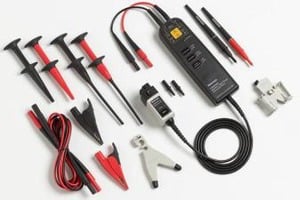
- The THDP0100/THDP0200/TMDP0200 high-voltage differential probes are the best choice for making non-ground referenced, floating or isolated measurements. These probes provide bandwidths to 200 MHz and voltage ranges up to 6000 V.
- High voltage differential probe For MSO/DPO 70KC/D/DX
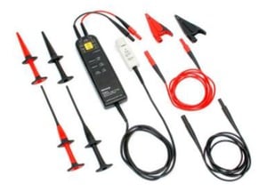
- The P5200A/P5202A/P5205A/P5210A high-voltage differential probes are the best choice for making non-ground referenced, floating or isolated measurements. These probes provide bandwidths to 100 MHz and voltage ranges up to 5600 V.
- AC/DC current probe
-
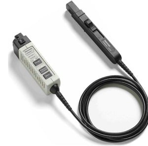
Tektronix current probe solutions offer the broadest range of AC/DC and AC-only current probes for measuring currents from microAmps to 2000 A. These probes provide bandwidths up to 120 MHz and best-in-class current clamp sensitivity down to 1 mA.

- Mid-voltage differential probe
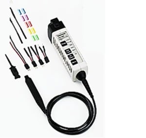
- The TDP0500/TDP1000 medium-voltage differential probes are the best choice for making non-ground referenced, floating or isolated measurements. These probes provide bandwidths to 1 GHz and voltage ranges up to ±42 V (DC + pk AC).
- Tektronix oscilloscopes and probes supported.
- For a complete listing of compatible probes for each oscilloscope, please refer to http://www.tek.com/probes for specific information on the recommended models of probes and any necessary probe adapters.


