Introduction
This document compares the response times of the model 428 current amplifier to the model 6485 and 6487 picoammeters.
Many sensitive instrument products such as picoammeters or electrometers provide an analog output that can be monitored with a data acquisition board or digitizing scope in order to maximize the speed of measurement. These analog output signals from the instruments have rise time specifications which indicate much faster measurements can be achieved from this analog output signal than with the instrument's front panel or over the IEEE-488 or RS-232 bus.
Methods
If a capacitor is put in series with a triangle wave, the resulting current will be a square wave. This technique is used to deliver a square wave of current to the evaluated instruments: 6487, 6485 and a 428. An axial capacitor (50pF) was placed inside a shielded BNC connector box (such as the Pomona model 3231). A 10Hz triangle wave from a function generator was feed through the capacitor into the input of the instruments. BNC to Triax adaptors were used to maximize the use of triax cable for all connections. A KPCMCIA-16AIAO-C card was used to sample the analog output signal from the instruments and also the triangle wave into the capacitor. This allows comparison of the response time of the output relative to the applied stimulus. The per-channel sampling rate was 50KHz and a gain of 1 was used for the KPCMCIA data acquisition card.
Results
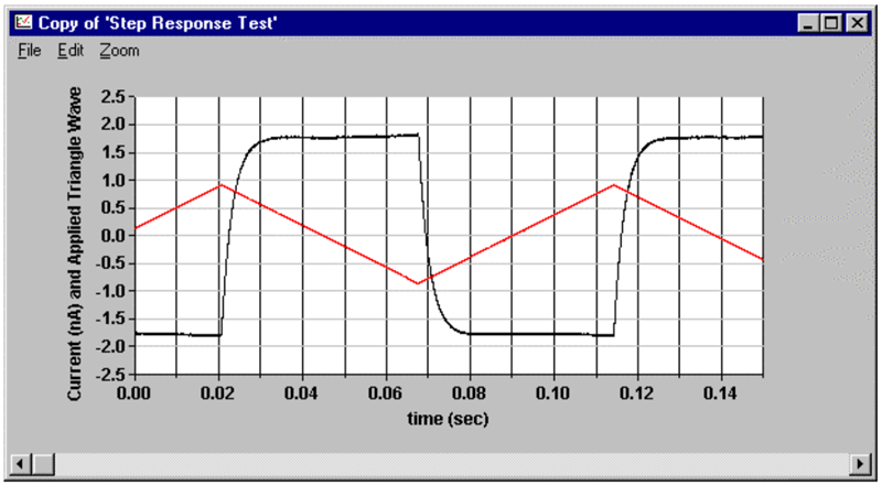
Below are data from a model 6487 Picoammeter. The picoammeter was on the 2nA range; dampening was OFF. The red trace is the triangle wave input to the capacitor (in volts). The black trace is the analog output from the 6487 (in nA). At each point of inflection of the triangle wave, the analog output will change polarity. The graph demonstrates the response time of the 6487.

Below are data from a model 6485 picoammeter. The picoammeter was on the 2nA range; filtering was OFF. As the graph demonstrates, similar to the results with the 6487, there is a significant response time. The response time of the 6485 is longer than for the 6487

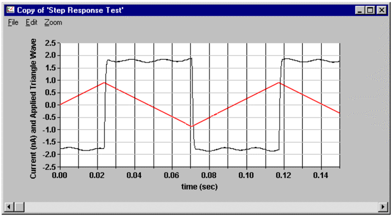
Below are data from the model 428 current amplifier. The same 10Hz triangle wave was feed through a 50pF capacitor into the input of the 428. A gain of 1E9 was used. The response time filter was off. In this circumstance, we have a greatly improved response time, however there is significant noise present in the flat portions of the curve. This noise has a period consistent with 60Hz noise. The function generator is most likely emitting an error signal from it’s internal power supplies. The faster response time of the 428 allows this signal to be seen on the analog output whereas the slower responding 6485 or 6487 filter this component out. This is a typical trade off between speed and stability.

However, the 428 has some very flexible filtering options as the next graph shows. In this case, the applied signal is unchanged, but the programmable rise time filter feature was turned on. A rise time of 1 msec was used. As can be seen, the noise is reduced but at the expense of response time. Even so, these data clearly demonstrate the superior response time of the 428 current amplifier for situations where measurement of a rapidly changing signal is the primary goal.

Conclusions
Monitoring the analog output of a picoammeter with a high speed digitizer can yield a faster responding signal than when using the instrument’s front panel or taking measurements over the bus. However, an upper limit on response time is still present and must be taken into account. When the signal of interest has a rapid rate of change, the model 428 current amplifier offers the best response time performance.

