Contactez-nous

Chat en direct avec un représentant Tek. Service disponible de 9 h à 17 h, CET jours ouvrables.

Téléphone

Appelez-nous au

Disponible de 9 h à 17 h CET jours ouvrables.

Télécharger

Télécharger des manuels, des fiches techniques, des logiciels, etc. :

TYPE DE TÉLÉCHARGEMENT
MODÈLE OU MOT CLÉ

Feedback

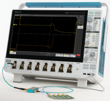
Time Domain Reflectometry (TDR) Analysis

4/5/6 Series B MSO Options 4-TDR, 5-TDR, and 6-TDR Datasheet

4/5/6 Series B MSO Options 4-TDR, 5-TDR, and 6-TDR Datasheet

The Tektronix Time Domain Reflectometry (Opt. TDR) measurement solution offers a wide range of features to debug and characterize the impedance of power integrity circuits, PCBs, high-speed applications, cables, and interconnects. TDR is usually applied using specialized sampling equipment in the time domain or VNA’s looking at frequency domain data. Sampling oscilloscopes continue to be a cost-effective solution but are not as ubiquitous as real-time oscilloscopes. Tektronix offers new TDR measurement capability on versatile 4/5/6 Series B MSO real-time oscilloscopes with up to 10 GHz of acquisition bandwidth capabilities and 7.5 GHz of TDR bandwidth capabilities. Engineers can perform TDR measurements with a simple setup including the Tektronix mixed signal oscilloscope, TDR module, and either SMA cables or TDR probe.

Key features

  • Time Domain Reflectometry (Opt. TDR) on real-time 4/5/6 Series B MSOs with up to 10 GHz of acquisition bandwidth capabilities and 7.5 GHz of TDR bandwidth capabilities
  • Automatic impedance profiling using TDR signals in real time
  • Measure either single-ended or differential Z, L, C at the region of interest
  • Save results, data, and reports along with impedance traces. Recall later for offline analysis
  • Automatic one-click Preset function prepares the TDR for measurements and performs calibration for open, short and load impedances together
  • Automatic math channel setup to show impedance traces

Key application areas for TDR

  • Low cost solution for PCB coupon testing
  • Verify characteristic impedance of transmission lines like cables and PCB traces
  • Measure trace length, cable length, and signal delays
  • Measure signal path rise/fall time and overshoot/undershoot
  • Support cable and trace loss modelling
  • Verify the integrity of cable crimps and connector launches
  • Determine cable/PCB dielectric constants
  • Measure frequency bandwidth, rise/fall time, and flatness of lab instruments and probes

TDR setup

The TDR setup requires a 4/5/6 Series B mixed signal oscilloscope and the J2154A PerfectPulse Differential TDR from Picotest. The J2154A is a differential pulse generator. It supports either single-ended or differential TDR measurements. For performing TDR measurements on a printed circuit board, a probe is required to connect the pulse generator to the DUT.

Picotest probes like P2105A browser probe and P2103A differential TDR probe are used for single-ended and differential TDR measurements.

TDR_EN_US_61W 74085 0
Single-Ended TDR setup.

The connection shows the Single-Ended TDR setup to perform single-ended TDR measurement. The ports 3 and 4 are used for the oscilloscope and DUT connections.

TDR_EN_US_61W 74085 0
Differential TDR setup.

Differential TDR, shown in Differential TDR setup, requires two ports of the pulse generator to be connected to send the differential signal and analyze the differential signal reflected from the DUT, where the differential signal is a subtraction of positive and negative signals. The ports 1 and 3 connect the TDR signal to the oscilloscope and ports 2 and 4 connect the differential TDR signal to the DUT. The matched cables are used for differential TDR connections to minimize the skew.

Measurement and configurations

The TDR measurement is available after installing Option TDR and it is displayed in the StandardTime Measurements tab, as shown in the figure below.

TDR_EN_US_61W 74085 0
TDR measurement is added via the Time Measurements section.

Once the measurement is added, the settings are available to configure and run the measurement, as shown in the figure below. You can specify the signal type as single-ended or differential for the TDR measurements. The TDR Preset automatically optimizes oscilloscope settings to acquire the signal properly and then calibrates each line of TDR using the average acquisition mode to reduce the noise on the signal. It also sets the optimal sample rate and horizontal scale to accommodate the incident and first reflection of the voltage.

TDR_EN_US_61W 74085 0
Settings for TDR measurements.

TDR calibration (TDR Preset)

Unlike a VNA instrument, the TDR Preset avoids the need for a separate 3-step calibration with open, short, and load impedances. Instead, it uses the TDR pulse waveform generated by the pulse generator along with any standard 50 ohm cable on the far end to find the calibration constants. When the TDR Preset is clicked, the oscilloscope will automatically adjust the horizontal, vertical, and trigger settings for optimal calibration. The algorithm then finds the calibration constants using the TDR pulse and compensates the reflection coefficient and impedance traces directly. There is no need to go through multiple manual calibration steps and oscilloscope settings.

Impedance, inductance, and capacitance

The TDR analysis automatically calculates the reflection coefficient (rho) versus time waveform from the reflected signal and plots an impedance (Z) versus time trace. A measurement badge displays the impedance (Z), capacitance (C), and inductance (L) by automatically identifying the region of interest where the impedance has changed. In cases of multiple impedance variations, you can identify the region of interest by positioning the cursors around the region and using cursor gating to limit the measurement to a particular region.

For example, the TDR signal passes through a Picotest PCB demo trace at test point TP4, as shown in figure PCB trace. Notice the impedance variations across the entire signal path and observe that the impedance is lower in the middle region due to the wider PCB path. Additionally, observe the initial bumps in the curve that indicate the inductive and capacitive characteristics of the probe tip. The TDR measurement automatically identifies the first capacitance and inductance regions and provides the corresponding values of C and L. Furthermore, you can easily measure capacitance and inductance at any regions of the waveform using cursor gating.

TDR_EN_US_61W 74085 0
Making a TDR measurement on a PCB trace with impedance variations. Note how the trace widens in the center.
TDR_EN_US_61W 74085 0
The TDR analysis provides an impedance waveform for the trace in the above figure. The impedance, capacitance and inductance of the waveform across marked regions are displayed in a measurement badge. The lower impedance in the center of the screen corresponds to the wider section of the PCB trace.

TDR bandwidth

The TDR system bandwidth is the effective bandwidth calculated using rise time of TDR step generator (trTDR), oscilloscope (trscope), and TDR probe (trprobe).

TDR_EN_US_61W 74085 0

Where,

trTDR = the TDR rise time or fall time from10% to 90%

trscope = the oscilloscope rise time or fall time from 10% to 90%

trprobe = the probe rise time or fall time from 10% to 90%

For example, the 6 Series B MSO with bandwidth of 10 GHz (40 ps rise time) combined with the J2154A Picotest pulse generator with bandwidth of 13 GHz (34 ps rise time), and a P2105A TDR probe with bandwidth of 16 GHz (21.88 ps rise time) result in an effective bandwidth of 6.15 GHz (56.9 ps rise time) because the rise times combine as the square root of the sum of the squares.

Report generation and saving waveforms

After measurement execution the waveform data or session files can be saved to document results or for the further analysis. The measurement results can be exported to report files in .mht or .pdf formats.

A report generated for a single-ended TDR analysis of a printed circuit board is shown below.

TDR_EN_US_61W 74085 0

Ordering information

Models and software licenses

ProductOptionsSupported instrumentsBandwidth available
New instrument purchase option6-TDR6 Series B MSO (MSO64B, MSO66B, and MSO68B
  • 1 GHz
  • 2.5 GHz
  • 4 GHz
  • 6 GHz
  • 8 GHz
  • 10 GHz
Product upgrade optionSUP6-TDR
Floating licenseSUP6-TDR-FL
New instrument purchase option5-TDR5 Series B MSO (MSO54B, MSO56B, and MSO58B), MSO58LP
  • 350 MHz
  • 500 MHz
  • 1 GHz
  • 2 GHz
Product upgrade optionSUP5-TDR
Floating licenseSUP5-TDR-FL
New instrument purchase option4-TDR4 Series B MSO (MSO44B and MSO46B)
  • 200 MHz
  • 350 MHz
  • 500 MHz
  • 1 GHz
  • 1.5 GHz
Product upgrade optionSUP4-TDR
Floating licenseSUP4-TDR-FL

Software bundles

BundleOptionsDescription
6 Series B MSO6-PRO-POWER-1Y 1 Year License Pro Power Bundle
6-PRO-POWER-PER Perpetual License Pro Power Bundle
6-ULTIMATE-1Y 1 Year License Ultimate Bundle
6-ULTIMATE-PER Perpetual License Ultimate Bundle
6-ULTIMATE-3Y3 Year License Ultimate Bundle
6-ULTIMATE-FTFloating License Ultimate Bundle
5 Series B MSO5-PRO-POWER-1Y 1 Year License Pro Power Bundle
5-PRO-POWER-PER Perpetual License Pro Power Bundle
5-ULTIMATE-1Y 1 Year License Ultimate Bundle
5-ULTIMATE-PER Perpetual License Ultimate Bundle
5-ULTIMATE-3Y3 Year License Ultimate Bundle
5-ULTIMATE-FTFloating License Ultimate Bundle
4 Series B MSO4-PRO-POWER-1Y 1 Year License Pro Power Bundle
4-PRO-POWER-PER Perpetual License Pro Power Bundle
4-ULTIMATE-1Y 1 Year License Ultimate Bundle
4-ULTIMATE-PER Perpetual License Ultimate Bundle
4-ULTIMATE-3Y3 Year License Ultimate Bundle
4-ULTIMATE-FTFloating License Ultimate Bundle

Recommended accessories

ModelDescription Quantity
J2154A PerfectPulse® Differential TDR (J2154A)
  • PerfectPulse Differential TDR Picotest TDR Demo Trace Board
  • Two (2) 12” BNC-SMA PDN Cables USB-C Cable
1
P2103A Differential TDR Probe (P2103A)
  • Differential TDR Probe with 50 and 100 mil pitch tips
  • Two (2) 0.5m SMA-Mini SMP PDN Cables TDR DiffPair Demo Board
1
P2105A 1-Port TDR Probe (P2105A-1X)
  • 1-Port Probe Head
  • One (1) 1m SMA-Mini SMP PDN Cable
1