Contactez-nous
Chat en direct avec un représentant Tek. Service disponible de 9 h à 17 h, CET jours ouvrables.
Appelez-nous au
Disponible de 9 h à 17 h CET jours ouvrables.
Télécharger
Télécharger des manuels, des fiches techniques, des logiciels, etc. :
Feedback
Series 2280S Precision Measurement, Low Noise, Programmable DC Power Supplies
Series 2280S Datasheet
Plus d’informations
- Gamme Keithley 2280S
- Assistance produit
- Découvrez d'autres modèles Alimentation DC
Lire en ligne :
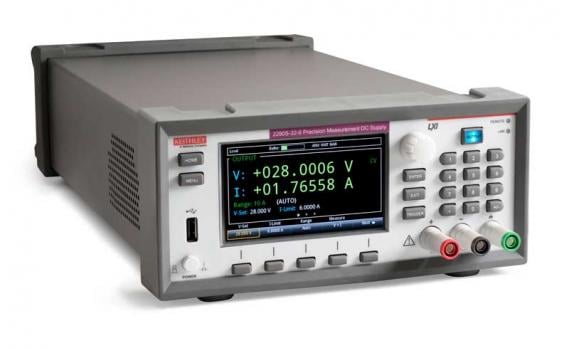
The Series 2280S Precision Measurement, Low Noise, Programmable DC Power Supplies are much more than just sources of clean power; they are also precision measurement instruments. They can source stable, low noise voltages as well as monitor load currents over a wide dynamic range from amps to nanoamps.
The Model 2280S-32-6 can output up to 32V at up to 6A; the Model 2280S-60-3 can output up to 60V at up to 3.2A.
Both supplies use linear regulation to ensure low output noise and superior load current measurement sensitivity. A high resolution color Thin Film Transistor (TFT) screen displays a wide range of information on measurements.
Soft-key buttons and a navigation wheel combine with the TFT display to provide an easy-to-navigate user interface that speeds instrument setup and operation. In addition, built-in plotting functions allow monitoring trends such as drift. This is unique in the bench power supply space.
These supplies provide the flexibility required for both benchtop and automated test system applications. For example, they provide a list mode, triggers, and other speed optimization functions to minimize test time in automated testing applications.
DMM-Quality Low Current Measurements with High Resolution
Unlike conventional power supplies, Series 2280S supplies can also make measurements with up to 6½ digits of resolution. Voltage output measurements can be resolved down to 100µV. These supplies measure load currents from 100nA to amps and can resolve down to 10nA.
Four load current measurement ranges (10A, 1A, 100mA, and 10mA) support measuring a device’s full load current, standby mode current, and small sleep mode currents with DMM-quality accuracy.
The high resolution allows characterizing small changes in load currents with confidence. It also makes it possible to make a broad range of measurements on a single range with excellent accuracy across both low and high current values.
Measure Rapidly Changing Load Currents
Capture measurements with either an external control signal or an analog level threshold crossing
To monitor fast-changing and pulse-like load currents properly, Series 2280S supplies offer the speed necessary to capture load changes that occur at intervals as short as 140µs.
This capability allows designers and manufacturers of portable, battery-operated devices to monitor load currents easily in all of a device’s operating modes so they can determine the device’s total power consumption.
This high speed measurement capability allows measuring each state of a power-up load sequence and a power-down sequence. Measurements can be made as fast as 2500 readings per second, making it possible to characterize and test the current draw at each of the start-up states.

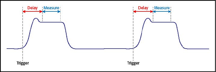
Figure 1. Make time-critical measurements on fast-changing or pulse-like loads. An external trigger initiates the acquisition.
Programmable delay and measure times enable measurements at a specific time on the load current pulse. In addition to the digital trigger, a level threshold setting can be used to store up to 2500 measurements at a programmed reading rate.
The measurements can be captured using either of two methods. A measurement can be initiated by a digital external control signal transmitted to the external input of the digital I/O port.
In addition, up to 2500 measurements can be stored at a sampling rate up to 2800 readings/s based upon a programmed threshold level. The user selects both the level and the slope of the signal, a rising signal or a falling signal.
The level setting can be used to store either voltage and/or current measurements when the threshold level is crossed. When the level threshold is enabled, the supply is continuously monitoring the level of the selected parameter and buffering the measurements.
Thus, pre-threshold measurements can be saved along with the post-threshold measurements.
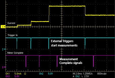
Figure 2. Measure the start-up load currents as a device powers up.
View and Control Every Parameter of the Supply for Maximum Performance
The bright, 4.3-inch TFT display shows voltage and current readings, the source settings and many additional settings in large, easy-to-read characters. The icon-based main menu provides all the functions users can control and program for fast access to source setup, measurement setup, display formats, trigger options, and system settings.
Menus are short, and the menu options you need are easy to find and clearly described, so that you can set up test parameters quickly by using the navigation wheel, keypad, or soft-keys. Many set-up parameters, such as for voltage and current settings, can be entered directly from the home screen; less complex tests don’t even require accessing the main menu to make adjustments.
Whether your test’s requirements are uncomplicated or complex, the Series 2280S supplies provide a simple way to set up all the required parameters.
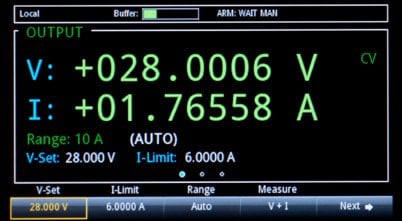
Figure 3. Adjust voltage, current, the current range, the measurement mode, protection levels, and other functions from the home screen.

Figure 4. Access the full functionality of the Series 2280S supplies from the main menu.
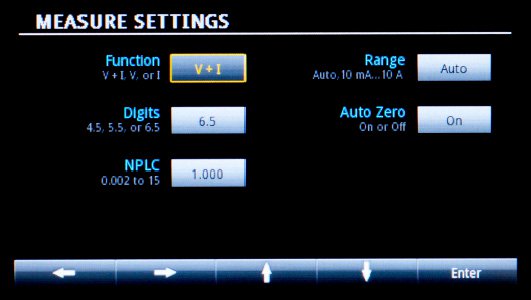
Figure 5. Configure the readback measurements exactly the way you need them using a Measure Sub-screen.
Controlled Rise and Fall Times Protect Devices Under Test
Are you working on a device or a system with a high in-rush current? Series 2280S supplies allow programming the voltage output’s rise time to slow the voltage ramp and avoid voltage overshoot, which could potentially damage the DUT.
The voltage fall time can also be controlled to prevent a fast ramp down of the output voltage. Voltage rise and fall times can be set as slow as 10V/s or as fast as 100V/s. Small voltage transitions can be programmed to rise and fall as fast as 1000V/s.
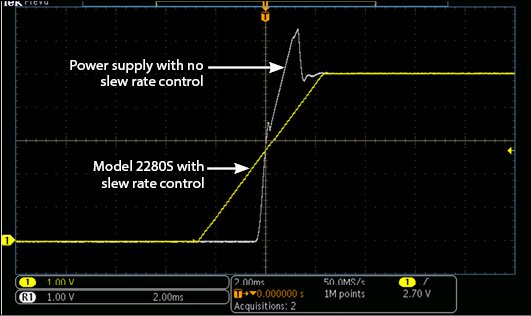
Figure 6. Programmable slew rates permit controlling voltage rise and fall rates, preventing undesirable transients during power up of capacitive loads.
Perform Semi-Automated Testing Right on Your Bench
Test your design over its operating voltage range automatically or study how it responds to DC output changes by using the Series 2280S supplies’ built-in List Mode function. Create and save up to 10 lists of sequenced voltage levels with up to 99 distinct voltages in each list.
The duration of each voltage level can be set as short as 1ms or as long as 60s. Create simple linear ramps or any custom configuration from either the front panel or an interface bus. A single trigger will automatically execute the list once or multiple times.
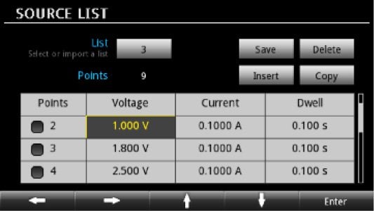
Figure 7A. Create an output sequence using the List setup screen.
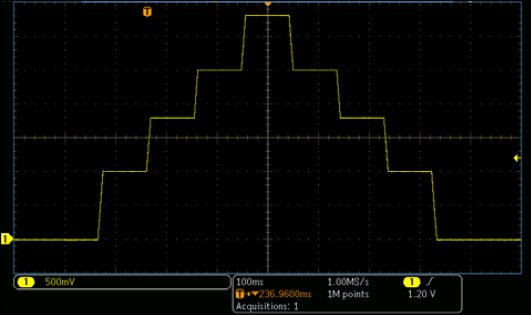
Figure 7B. Use the list mode to step the output voltage automatically through a series of levels. The voltages were created by the list shown in Fig. 7A.
Trend Analysis and Load Current Characterization
Use the built-in graphing function to monitor the stability of the load current or capture and display a dynamic load current. Or, use it to view a start-up or turn-off load current. Series 2280S supplies can take measurements quickly and store up to 2,500 measurement points.
In addition to displaying a voltage or current waveform or both, they can compute statistics on the stored data. Statistical calculation options include average, maximum, minimum, peak-peak, and standard deviation. All the information you need is accessible through a few display menus.
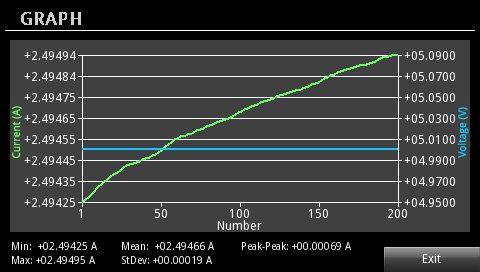
Figure 8. Monitor voltage, current, or both with the graphing function.
Simple, Yet Powerful Data Logging
As well as capturing 2500 data points in the internal memory and displaying it using the Series 2280S graphing function, voltage and current measurements can be collected using the LAN interface and the Series 2280S built-in web browser. The web interface home page offers a data logging option.
Measurements can be taken over a programmed time interval, based on a programmed number of data points, or manually using the Start/Stop button on the webpage user interface. Using the web-based data logger, measurements can be continuously taken over multiple days.
Figure 9 shows a web page display of the measurements, the time when measurements were taken, and a number of status parameters. Statistics on the logged data are displayed on the page and include maximum, minimum, and average values.
The total consumed electric chage in milliamp-hours is also computed. Control buttons on the side of the display allow control of the data logging and enable copying of either selected rows or all the data.
The data can be easily pasted into a report or a spreadsheet for analysis. Just interface to a Series 2280S via LAN and select the data logging option. This powerful data logging capability requires no programming.
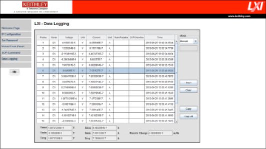
Figure 9. Web page display of the LXI-data logging function showing all parameters stored and the associated statistics.
Automate a Test Quickly and Easily with KickStart Software
Set up an automated test for the Series 2280S supplies in four simple steps with the KickStart start-up software. KickStart is available for installation on your PC via a free download from www.keithley.com.
Once the program is open, perform these steps: create a test file, select the 2280S power supply, select the power supply application, and enter the test parameters. Run the test, and get results without having to write a line of code. KickStart provides both graph and spreadsheet displays.
Data is saved to the test file, and the data can be exported to data analysis programs. Or take a screen shot of the plot for reproduction in test reports. Up to 15,000 data points can be stored. KickStart may be all the software you ever need.
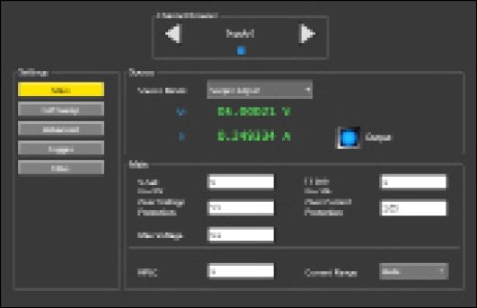
Figure 10. KickStart DC power main screen.
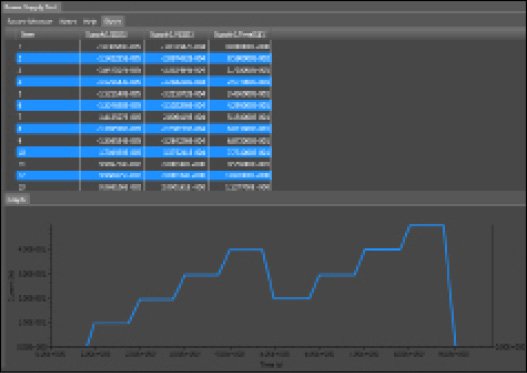
Figure 11. KickStart plot with measurement table.
Optimized Performance for Production Test
Series 2280S supplies are as powerful in a production test system as they are flexible on the R&D benchtop. In addition to their List Mode function, several other Series 2280S features help minimize test time in automated systems.
For example, an external trigger input allows hardware synchronization and control by other instruments in the test system. To eliminate many system delays, Series 2280S supplies produce a “measurement complete output” to signal the test system when the supplies have completed their required actions.
To reduce measurement time, the reading speed can be increased by reducing the acquisition time from power line cycle integration times, 16ms at 60Hz (20ms at 50Hz), to 33μs (40μs).
Furthermore, the Series 2280S supplies can sink up to 0.45A. Thus, these supplies can quickly discharge a voltage level and change to a different voltage.
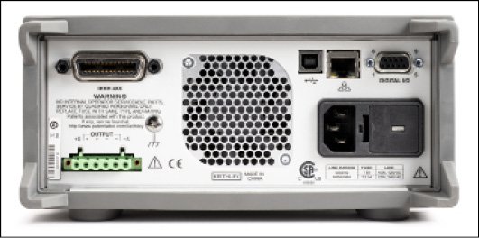
Figure 12. Series 2280S rear panel showing the rear output connector with remote sense inputs, digital I/O, and the three interfaces (GPIB, USB, and LAN).
A choice of front or rear panel terminals provides enhanced connection flexibility. For maximum voltage accuracy, 4-wire remote sensing ensures that the output voltage programmed is actually the level applied to the load. In addition, the sense lines are monitored in order to detect any breaks in them.
These features ensure any production problems can be quickly identified and corrected. Four additional digital I/O pins can provide fault status outputs or control an external relay or status lamp.
Series 2280S supplies can be controlled via their built-in GPIB, USB, or LAN interfaces. The USB interface is test and measurement system (TMC) compliant.
The LXI Core compliant LAN interface supports controlling and monitoring a Series 2280S supply remotely, so test engineers can always access the power supply and view measurements, even if they’re located on a different continent than their test systems.
To facilitate production test software development, native National Instruments LabVIEW™ drivers, IVI-C and IVI-COM drivers are available on the Keithley website, www.tek.com.
Specifications
23°C ±5°C with 1-hour instrument warm-up.
DC output ratings
|
2280S-32-6 |
2280S-60-3 |
|
|
Voltage |
0 to 32 V |
0 to 60 V |
|
Current |
0 to 6 A |
0 to 3.2 A |
|
Maximum Power |
192 W |
192 W |
Voltage 1
Source Setting
|
2280S-32-6 |
2280S-60-3 |
|
|
Accuracy |
± (0.02% + 3 mV) |
± (0.02% + 6 mV) |
|
Resolution |
1 mV |
1 mV |
Measurement2 (0.5V over-range)
|
2280S-32-6 |
2280S-60-3 |
|
|
Accuracy |
± (0.02% + 2 mV) |
± (0.02% + 4 mV) |
|
Resolution |
0.1 mV |
0.1 mV |
Additional Offset at faster measurement settings
|
2280S-32-6 |
2280S-60-3 |
|
|
5½ (0.1 PLC) |
0.21 mV |
0.40 mV |
|
4½ (0.01 PLC) |
1.44 mV |
2.7 mV |
|
3½ (0.002 PLC) |
7.60 mV |
14.25 mV |
Regulation
|
2280S-32-6 |
2280S-60-3 |
|
|
Load |
±(0.01% + 2 mV) |
±(0.01% + 2 mV) |
|
Line |
±(0.01% + 1 mV) |
±(0.01% + 1 mV) |
Output Ripple and Noise
|
2280S-32-6 |
2280S-60-3 |
|
|
Bandwidth 20Hz–20MHz |
< 1mVRMS |
< 2mVRMS |
|
< 5mV p-p |
< 7mV p-p |
Load Transient Recovery Time: Resistive load change 50% load to 100% load or 100% load to 50% load: <50µs to within 15mV of V-set.
Slew Rate: Rising voltage and falling voltage: 10V/s to 100V/s. Up to 1000V/s under limited conditions3. 100V/s (default).
Maximum Source Voltage Drop per Lead: To maintain specified voltage accuracy: 1V.
Maximum Sense HI and Sense LO Lead Resistance: To maintain specified voltage accuracy: 2Ω.
Current
Current Limit Setting
|
2280S-32-6 |
2280S-60-3 |
|
|
Full-scale Amps |
6 A |
3.2 A |
|
Accuracy |
±(0.05% + 5 mA) |
±(0.05% + 5 mA) |
|
Resolution |
0.1 mA |
0.1 mA |
Measurement 4 (120% over-range except 10A)
|
Range |
Resolution |
2280S-32-6 |
2280S-60-3 |
|
10 mA |
10 nA |
±(0.05% + 10 µA) |
±(0.05% + 10 µA) |
|
100 mA |
100 nA |
±(0.05% + 10 µA) |
±(0.05% + 10 µA) |
|
1 A |
1 μA |
±(0.05% + 250 µA) |
±(0.05% + 250 µA) |
|
10 A |
10 μA |
±(0.05% + 250 µA) |
±(0.05% + 250 µA) |
Additional Offset at faster measurement settings9
|
Measure Resolution and (NPLC) |
Range |
2280S-32-6 |
2280S-60-3 |
|
5½ (0.1 PLC) |
10 mA |
5.0 µA |
5.0 µA |
|
100 mA |
20 µA |
20 µA |
|
|
1 A |
80 µA |
80 µA |
|
|
10 A |
2.0 mA |
2.0 mA |
|
|
4½ (0.01 PLC) |
10 mA |
20 µA |
20 µA |
|
100 mA |
40 µA |
40 µA |
|
|
1 A |
500 µA |
500 µA |
|
|
10 A |
10 mA |
10 mA |
|
|
3½ (0.002 PLC) |
10 mA |
30 µA |
30 µA |
|
100 mA |
250 µA |
250 µA |
|
|
1 A |
25 mA |
25 mA |
|
|
10 A |
75 mA |
75 mA |
Current Pulse Measurement 5
|
2280S-32-6 |
2280S-60-3 |
|
|
Minimum Pulse Width (10mA and 100mA range) 6 |
2.1 ms |
2.1 ms |
|
Minimum Pulse Width (1A and 10A range) 6 |
140 µs |
140 µs |
|
Minimum time to capture two consecutive pulses |
0.5 ms |
0.5 ms |
Regulation
|
2280S-32-6 |
2280S-60-3 |
|
|
Load |
±(0.01% + 0.25 mA) |
±(0.01% + 0.25 mA) |
|
Line |
±(0.01% ± 0.25 mA) |
±(0.01% ± 0.25 mA) |
Output Ripple and Noise
|
2280S-32-6 |
2280S-60-3 |
|
|
Bandwidth 20Hz–20MHz |
< 3mA RMS |
< 3mA RMS |
Maximum Continuous Average Sink Current
|
2280S-32-6 |
2280S-60-3 |
|
|
Non-programmable |
0.45 A ±15% |
0.45 A ±15% |
System Measurement Speeds
|
Settings |
Concurrent ( V+I ) |
Current or Voltage (I or V) |
|||
|
Readings/s |
Measure Resolutionand (NPLC) |
Autozero On 60 Hz (50 Hz) |
Autozero OFF 60 Hz (50 Hz) |
Autozero On 60 Hz (50 Hz) |
Autozero OFF 60 Hz (50 Hz) |
|
‘Read?’ with BUS Transfer |
6½ (5 PLC) |
2.0 (1.5) |
5.4 (4.5) |
2.5 (2.3) |
9.0 (8.5) |
|
6½ (1 PLC) |
9.0 (8.0) |
20 (18) |
11.5 (9.5) |
30.0 (28) |
|
|
5½ (0.1 PLC) |
48 (38) |
50 (48) |
50.0 (48.0) |
95.0 (85.0) |
|
|
‘*TRG’ into Memory |
4½ (0.01 PLC) 7 |
440 (430) |
1915 (1820) |
||
|
3½ (0.002 PLC) 7 |
510 (510) |
2668 (2650) |
|||
Protection
|
Overvoltage Protection (OVP) |
2280S-32-6 |
2280S-60-3 |
|
Setting Accuracy |
±(0.25% + 0.25 V) |
±(0.25% + 0.5 V) |
|
Resolution |
125 mV |
250 mV |
|
Response Time |
6 ms (typical)8 |
6 ms (typical)8 |
|
Overcurrent Protection (OCP) |
2280S-32-6 |
2280S-60-3 |
|
Setting Accuracy |
±(0.25% + 0.10 A) |
±(0.25% + 0.10 A) |
|
Resolution |
25 mA |
12.5 mA |
|
Response Time |
6 ms (typical)8 |
6 ms (typical)8 |
|
Overtemperature Protection (OTP) |
2280S-32-6 |
2280S-60-3 |
|
Output turn-off Temperature |
>93°C (typical) |
>93°C (typical) |
|
Response Time |
6 ms (typical)8 |
6 ms (typical)8 |
Other Timing Data
CV to CC Transition Time — (V-Set = 5V, I-limit = 0.5A, Resistive Load change 25Ω to 2.5Ω): 2.4ms.
CC to CV Transition Time (V-Set = 5V, I-limit = 0.5A, Resistive Load change 2.5Ω to 25Ω:1.1ms.
Function Change (from detection of bus command to function change completed): 10ms (typical).
Output Off/On (from detection of bus command to voltage beginning to decrease):5ms (typical).
Reverse Leads Actuation: 6ms (typical)8.
Notes
- Specifications based on using remote sense connections. For 2-wire connections, add an offset of 0.5mV/A (Front terminals).
- 6½ digit resolution, 1 PLC reading rate, filter on, autozero on.
- 100V/s to 1000V/s rise and fall slew rates:2280S-32-6: limited to 5V changes at a maximum of 3A; between 0V to 5V, the load current can be up to full load, 6A 2280S-60-3: limited to 10V changes at a maximum of 2A; between 0V and 10V, the load current can be up to full load, 3.2A.
- 6 ½ digit resolution, 1PLC integration time, Autozero: on, Filter: on 10mA and 100mA ranges: Source Delay: 2ms1A and 10A ranges: Source Delay: 1ms.
- Settings: Autozero: off, 0.002 PLC, Arm Source: External, Trigger Source: Immediate, Filter: off10mA and 100mA ranges: Source Delay: 2ms1A and 10A ranges: Source Delay: 0ms or off
- Time includes trigger detection, jitter, and 0.002PLC integration time.
- Settings: Autozero: off, Output Delay: off, Source Delay: off, voltage output is constant, Measure Count: 1000.
- Time defined as from detection of condition to start of output turn-off.
- Filter on, 10mA and 100mA ranges: Source Delay: 2ms 1A and10A ranges: Source Delay: 1ms
General
Common Mode Current: < 6µA peak-peak.
Chassis Isolation: ±240V, any terminal to chassis. >1GΩ in parallel with <6.8nF.
Temperature coefficient: Add the following to all accuracy specifications when outside the range, 23°C ±5°C: (0.15 × specification)/°C for 0° to 18°C and 28° to 40°C.
Measurement Display Modes: Voltage and current, voltage only, current only.
Measurement Acquisition Control: Continuous, Manual, External digital input, PC bus.
List Mode: — Maximum number of stored lists: 9.Number of points in a list: 2 – 99.List Storage Location: Internal memory or USB memory stick.
Math and Filter Functions:
REL: Removes offset from current reading display, Range: –1×10⁶ to +1×10⁶.
Mx+b: Reading = x, M = –1×10⁶ to +1×10⁶, b = –1×10⁶ to +1×10⁶.
Filter: Moving average, Count: 2–100, Window: 0.01% to 100%.
Memory Buffer:
2500 locations; each location contains: Voltage measurement, current measurement, CV/CC Mode, and time stamp, NVRAM.
Display: 4.3 in. front panel color display, resolution: 480 pixels × 272 pixels.
Display Modes:
Real time voltage and current readings and settings.
Plots of stored data: voltage vs data point, current vs data point, voltage and current vs. data point, 100 point resolution.
Plots can also display statistics: mean, maximum, minimum, peak-peak, standard deviation.
Table of stored data: time/date, voltage, current.
Soft button and navigation wheel control.
Communications:
GPIB: IEEE-488.2 compliant and status model topology.
LAN: RJ-45 connector, 10/100BT, Auto MDIX.
IP Configuration: Static or DHCP.
LXI Core 2011, version 1.4,
USB: — USB2.0 device (rear panel, type B), USBTMC compliant.USB2.0 host (front panel, type A), full speed, support USB Flash Drives.
Input Connections:
Front: (2-wire). Adjustable supporting, safety shrouded banana, spade lug, or wire.
Rear: (4-wire sense). 6-pin removal screw terminal, safety shrouded cover, removable local sense jumpers.
Real-Time Clock: Capacitive charged, 20 days between next power on cycle at 23°C and ≤50%RH.
Digital I/O: 9-pin female D-sub. 6 Input/Output pins.
Input Signal Levels:
0.7V (maximum logic low).
3.7V (minimum logic high).
Input Voltage Limits:
–0.25V (Absolute minimum).
+5.25V (Absolute maximum).
Maximum Source Current: +2.0mA@ >2.7V (per pin).
Maximum Sink Current: –50mA @ 0.7V (per pin, solid-state fuse protected).
5V power supply, limited to 0.5A @>4V (solid-state fuse protected).
Trig In minimum pulse ≥4µs, Logic Low pulse.
Meter Ready Pulse, 15–30µs, Logic Low Pulse.
EMC: Conforms to European Union EMC directive.
Safety:
U.S. NRTL Listing: UL61010-1 3rd ed 2012 and UL61010-2-030:2012.
Canadian Certification: CAN/CSA C22.2 No. 61010-1 3rd ed 2012.
European Union Compliance: Low Voltage Directive .
Cooling: Forced air, side intake and rear exhaust.
Power Supply: 100V/120V/220V/240V ±10%.
Power Line Frequency: 50/60Hz ±3Hz, automatically sensed at power-on.
Power Consumption: 630VA peak.
Operating Environment: 0° to 40°C, ≤80% RH up to 35°C, non-condensing. Altitude: up to 2000 meters.
Storage Environment: –25° to 70°C.
LXI Web Browser Compatible Operating System and Software: Windows 2000, Win 7 and XP compatible, supports Web browsers with Java plug-in (requires Java plug-in 1.7 or higher). Web page served by Model 2280S.
Rack Dimensions: (W×H×D), without boot: 213.8 × 88.4 × 383.3mm (8.42 × 3.48 × 15.1 in.).
Bench Dimensions: (W×H×D) with boot: 255.3 × 107.2 × 415.0mm (10.1 × 4.22 × 16.34 in.)
Shipping weight: 13.29kg (29.3 lbs.).
Net weight: 10.85kg (23.9 lbs.).
Warranty: 3 years.
Ordering Information
2280S-32-6 Precision Measurement DC Power Supply, 32V, 6A
2280S-60-3 Precision Measurement DC Power Supply, 60V, 3.2A
Accessories Supplied
Quick Start Guide
KickStart Quick Start Guide
User Documentation CD
LAN Crossover Cable
Power Cord
Rear Panel Mating Connector with Cover
ACCESSORIES AVAILABLE
2280-001 Rear Panel Mating Connector and Cover
174694600 LAN Crossover Cable
4299-7 Universal Fixed Shelf Rack-Mount Kit
4299-8 Single Fixed Rack-Mount Kit
4299-9 Dual Fixed Rack-Mount Kit
KPCI-488LPA IEEE-488.2 Interface Board for the PCI Bus
KUSB-488B IEEE-488.2 USB-GPIB Interface Adapter for USB Port with 2m (6.6 ft) cable
7007-1 Double Shielded Premium IEEE-488 Interface Cables, 1m (3.2 ft)

