Contactez-nous
Chat en direct avec un représentant Tek. Service disponible de 9 h à 17 h, CET jours ouvrables.
Appelez-nous au
Disponible de 9 h à 17 h CET jours ouvrables.
Télécharger
Télécharger des manuels, des fiches techniques, des logiciels, etc. :
Feedback
100GBASE-KR4, 100GBASE-CR4, & CAUI-4
100G-TXE Compliance Solution for Real-Time Oscilloscopes
Plus d’informations
- Oscilloscope hautes performances DPO70000SX ATI
- Découvrez d'autres modèles Logiciel pour oscilloscopes, produits keithley, et RF
Lire en ligne :
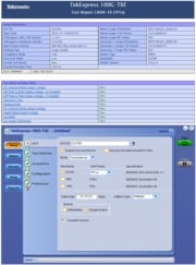
The TekExpress 100G-TXE provides turnkey testing and debug solutions for IEEE 802.3bj (100GBASEKR4/100GBASE-CR4) and IEEE 802.3bm (CAUI-4) electrical standards. These three electrical standards make-up the backbone of the current 100G Ethernet industry.
Key Features
- 100G-TXE offers streamlined and fully automated transmitter characterization of 802.3bj (100GBASE-KR4/100GBASE-CR4) electrical transmitter specifications and 802.3bm (CAUI) specifications
- Extends DPOJET for low level debug into 100GBASEKR4/100GBASE-CR4 and CAUI-4 1.
1CAUI-4 is also known as CAUI
Applications
- Electrical transmitter measurements
- Validation of 100GBASE-KR4/100GBASE-CR4 and CAUI-4
IEEE 802.3bj (100GBASE-KR4) electrical real-time transmitter measurements fully automated
| Parameter | Subclause reference | Value | Units |
|---|---|---|---|
| Signaling rate | 93.8.1.2 | 25.78125±100 ppm | GBd |
| Differential peak-to-peak output voltage (max) | |||
| Transmitter disabled | 93.8.1.3 | 30 | mV |
| Transmitter enabled | 93.8.1.3 | 1200 | mV |
| DC common-mode output voltage (max) | 93.8.1.3 | 1.9 | V |
| DC common-mode output voltage (min) | 93.8.1.3 | 0 | V |
| AC common-mode output voltage (RMS, max) | 93.8.1.3 | 12 | mV |
| Output waveform | |||
| steady-state voltage vf (max) | 93.8.1.5.2 | 0.6 | V |
| steady-state voltage vf (min) | 93.8.1.5.2 | 0.4 | V |
| Linear fit pulse peak (min) | 93.8.1.5.2 | 0.71 x vf | V |
| Normalized coefficient step size (min) | 93.8.1.5.4 | 0.0083 | - |
| Normalized coefficient step size (max) | 93.8.1.5.4 | 0.05 | - |
| Pre-cursor full-scale range (min) | 93.8.1.5.5 | 1.54 | - |
| Post-cursor full-scale range (min) | 93.8.1.5.5 | 4 | - |
| Coefficient initialization ratio | |||
| (c(0)+c(1)-c(-1))/(c(0)+c(1)+c(-1)) | 93.8.1.5.3 | 1.29±10% | - |
| (c(0)-c(1)+c(-1))/(c(0)+c(1)+c(-1)) | 93.8.1.5.3 | 2.57±10% | - |
| Signal-to-noise and distortion ratio (min) | 93.8.1.6 | 27 | dB |
| Output jitter (max) | |||
| Even-odd jitter | 93.8.1.7 | 0.035 | UI |
| Effective bounded uncorrelated jitter, peak-to-peak | 93.8.1.7 | 0.1 | UI |
| Effective total uncorrelated jitter, peak-to-peak | 93.8.1.7 | 0.18 | UI |

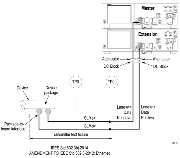
Transmitter test fixture and test points
IEEE 802.3bj (100GBASE-CR4) electrical real-time transmitter measurements fully automated
| Parameter | Subclause reference | Value | Units |
|---|---|---|---|
| Differential peak-to-peak output voltage (max) with Tx disabled | 92.8.3.1 | 35 | mV |
| DC common-mode output voltage (max) | 92.8.3.1 | 1.9 | V |
| AC common-mode output voltage, vcmi (max., RMS) | 92.8.3.1 | 30 | mV |
| Differential peak-to-peak voltage, vdi (max.) | 92.8.3.1 | 1200 | mV |
| Transmitter waveform | |||
| Transmitter steady-state voltage, vf (min) | 92.8.3.5.2 | 0.34 | V |
| Transmitter steady-state voltage, vf (max) | 92.8.3.5.2 | 0.6 | V |
| Linear fit pulse peak (min) | 92.8.3.5.2 | 0.45 × vf | V |
| Transmitted waveform | |||
| abs coefficient step size (min) | 92.8.3.5.4 | 0.0083 | - |
| abs coefficient step size (max) | 92.8.3.5.2 | 0.05 | - |
| minimum precursor full-scale ratio | 92.8.3.5.5 | 1.54 | - |
| minimum post cursor full-scale ratio | 92.8.3.5.5 | 4 | - |
| Coefficient initialization ratio | |||
| (c(0)+c(1)-c(-1))/(c(0)+c(1)+c(-1)) | 92.8.3.5.3 | 1.29±10% | - |
| (c(0)-c(1)+c(-1))/(c(0)+c(1)+c(-1)) | 92.8.3.5.3 | 2.57±10% | - |
| Signal-to-noise and distortion ratio (min) | 92.8.3.5.7 | 26 | dB |
| Output jitter (max.) | |||
| Even-odd jitter, peak-to-peak | 92.8.3.8.1 | 0.035 | UI |
| Effective bounded uncorrelated jitter, peak-to-peak | 92.8.3.8.2 | 0.1 | UI |
| Effective total uncorrelated jitter, peak-to-peak | 92.8.3.8.2 | 0.18 | UI |
| Signaling rate per lane | 92.8.3.9 | 25.78125±100 ppm | GBd |
| Unit interval nominal | 92.8.3.9 | 38.787879 | ps |
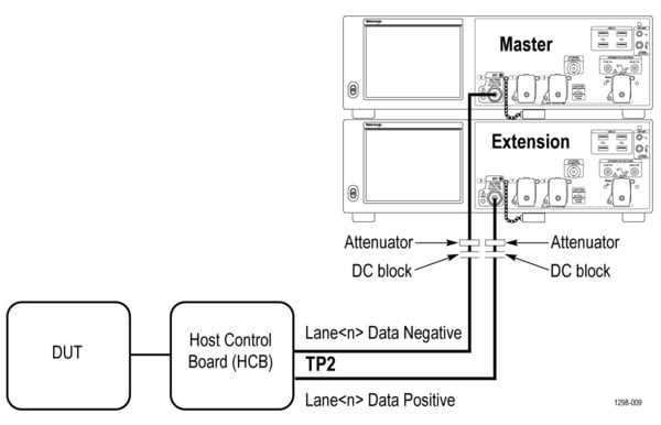
Transmitter test fixture and test points
IEEE 802.3bm (CAUI-4) electrical real-time transmitter measurements fully automated
| Parameter | Subclause reference | Value | Units |
|---|---|---|---|
| Signaling rate per lane (range) | 83E.3.1.1 | 25.78125 ± 100 ppm | GBd |
| DC common-mode output voltage (max) | 83E.3.1.2 | 2.8 | V |
| DC common-mode output voltage (min) | 83E.3.1.2 | –0.3 | V |
| Single-ended output voltage (max) | 83E.3.1.2 | 3.3 | V |
| Single-ended output voltage (min) | 83E.3.1.2 | –0.4 | V |
| AC common-mode output voltage (max, RMS) | 83E.3.1.2 | 17.5 | mV |
| Differential peak-to-peak output voltage (max) | |||
| Transmitter disabled | 83E.3.1.2 | 35 | mV |
| Transmitter enabled | 83E.3.1.2 | 900 | mV |
| Eye width (min) | 83E.3.1.6 | 0.46 | UI |
| Eye height A, differential (min) | 83E.3.1.6 | 95 | mV |
| Eye height B, differential (min) | 83E.3.1.6 | 80 | mV |
| Transition time (min, 20% to 80%) | 83E.3.1.5 | 10 | ps |
| Parameter | Subclause reference | Value | Units |
|---|---|---|---|
| Signaling rate per lane (range) | 83E.3.1.1 | 25.78125 ± 100 ppm | GBd |
| AC common-mode output voltage (max, RMS) | 83E.3.1.2 | 17.5 | mV |
| Differential output voltage (max) | 83E.3.1.2 | 900 | mV |
| Eye width (min) | 83E.3.2.1 | 0.57 | UI |
| Eye height, differential (min) | 83E.3.2.1 | 228 | mV |
| Vertical eye closure (max) | 83E.4.2.1 | 5.5 | dB |
| Transition time (min, 20% to 80%) | 83E.3.1.5 | 12 | ps |
| DC common mode voltage (min) 1 | 83E.3.1.2 | –350 | mV |
| DC common mode voltage (max)1 | 83E.3.1.2 | 2850 | mV |
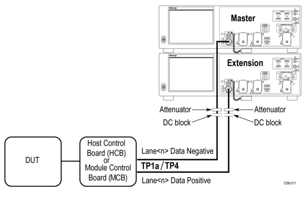
Transmitter test fixture and test points
Host Control Board (HCB) and Module Control Board (MCB) are for test points TP1a and TP4 respectively.
1DC common mode voltage is generated by the host. Specification includes effects of ground offset voltage.
Optional system probing setup
The bandwidth requirements of 100GBASE-KR4 are difficult to match with the browser or soldered down probes. However, for debug purposes, these 33 GHz and lower probes offer effective signal access on backplanes and chip-to-chip interconnects.
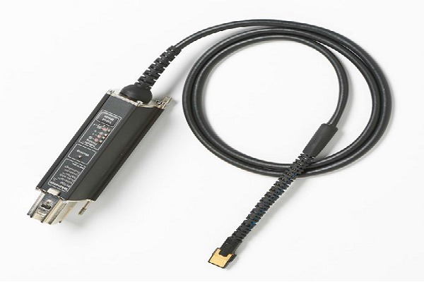
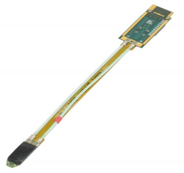
Backplane and chip-to-chip interconnects can be a significant probing challenge.
Electrical system interconnect setup
Direct electrical connections through a precision fixture or 2.92 mm interconnects are the preferred method to access the backplane and cabled signals. The QSFP28 module interconnect point found on 100GBASE-CR4 and CAUI-4 designs are the most typical signal access points.
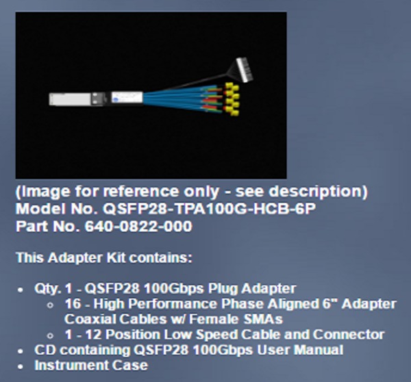
Refer to the Wilder Technologieswww.wilder-tech.com/qsfp-28-kits.htmfor details regarding the various methods of signal break-out.
100GBASE-KR4/100GBASE-CR4 measurement selection
The setup and test execution is simple with the 100G-TXE software. The oscilloscope acquisition and analysis are controlled through the 100G-TXE automation solution. The Graphical User Interface (GUI) provides an intuitive and easily repeatable workflow for setup and testing.
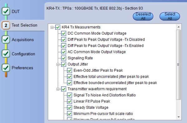
TekExpress ® 100GBASE-KR4 measurement setup
Alternately, a similar set of measurements without the Standards pass or fail criteria and reporting tools can be found as extensions to the DPOJET product. These would serve the debug user, rather than the compliance user.
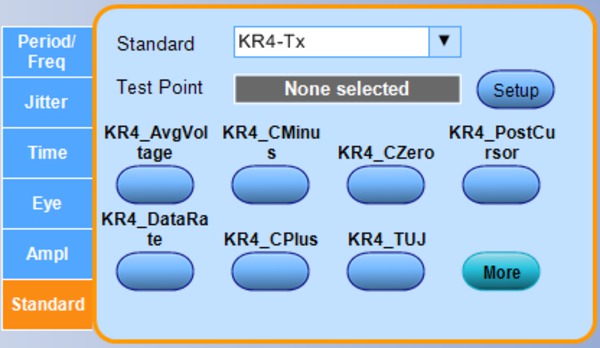
DPOJET Standard: 100GBASE-KR4 measurement setup
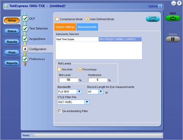
Design characterization is supported beyond 100GBASE-KR4/100GBASE-CR4/CAUI-4 compliance requirements for all measurements. The TekExpress 100G-TXE offers flexible control over test configurations such as analysis windows and other parameters. User-defined mode lets customers make changes to the test limits and perform marginal testing beyond compliance.
User-defined mode
In user-defined mode, users can configure Global parameters, test specific parameters, measurement repeat parameters, and notification parameters. This supports characterization measurements rather than developing custom lab setups, reducing testing time, and complexity.
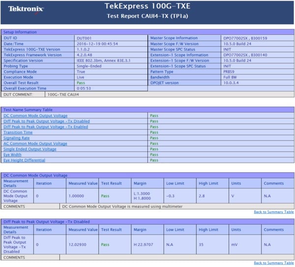
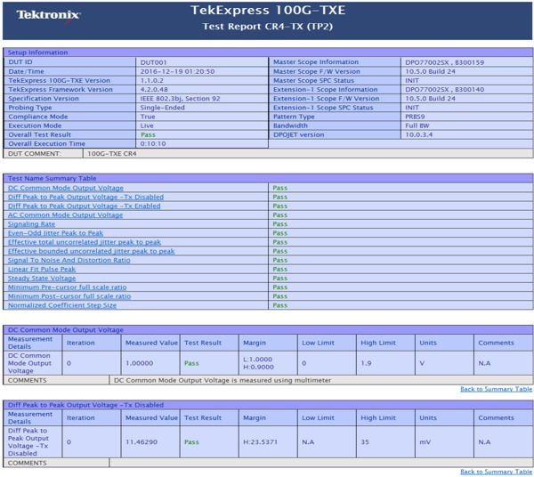
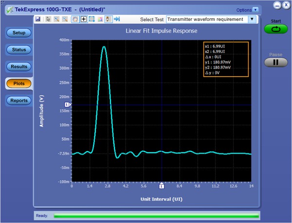
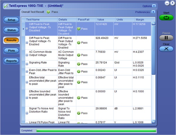
Reports & measurement results

Certifications
CE Marking Not Applicable.

- Tektronix is registered to ISO 9001 and ISO 14001 by SRI Quality System Registrar.
Ordering information
Models
- To order 100G-TXE (100GBASE-KR4/100GBASE-CR4) & CAUI-4 permanent node locked license With a DPS70KSX Real-Time Oscilloscope
- Oscilloscope DPS77704SX, DPS75904SX, DPS75004SX, DPS73308SX option 100G-TXE
- To order 100G-TXE (100GBASE-KR4/100GBASE-CR4) & CAUI-4 permanent node locked license With a DPO70KDX Real-Time Oscilloscope
- Oscilloscope DPO72304DX, DPO72504DX, DPO73304DX option 100G-TXE
- To order 100G-TXE (100GBASE-KR4/100GBASE-CR4) & CAUI-4 permanent node locked license With a MSO70KDX Real-Time Oscilloscope
- Oscilloscope MSO72304DX, MSO72504DX, MSO73304DX option 100G-TXE
- To order 100G-TXE (100GBASE-KR4/100GBASE-CR4) & CAUI-4 permanent node locked license With a DPO70KSX Real-Time Oscilloscope
- Oscilloscope DPO72304SX, DPO72504SX, DPO73304SX option 100G-TXE
- To order 100G-TXE (100GBASE-KR4/100GBASE-CR4) & CAUI-4 on a Floating License (any Real-Time Oscilloscope listed above)
- DPOFL-100G-TXE
- To order 100G-TXE (100GBASE-KR4/100GBASE-CR4) & CAUI-4 on a Free 30-Day Trial License (any Real-Time Oscilloscope listed above)
- DPOFT-100G-TXE
Recommended products
- Probes
- Tek P7633 (33 GHz) or Tek P7720 (20 GHz) probe
- Fixture
- Wilder MCB/HCB QSFP+ Breakout fixture (640-0786-000)


