
By Dorine Gurney
EMI/EMC testing is a critical step in bringing a product to market. There are two main categories of test: immunity and emissions testing. The purpose of immunity is to measure how a device will react when exposed to electromagnetic noise. Emission testing, which we will be discussing in this post, is done to ensure that any electromagnetic radiation from the product during normal operation is below a limit defined for that type of product. Most, if not all, electrical and electronic products require regulatory compliance testing. The test is performed in an approved test lab and can be an expensive proposition, especially if the product fails testing, costing a development program time and thousands of dollars.
To avoid multiple trips to the test house, it is highly recommended that you measure the noise that comes out of your product prior to going to the test house to increase your chances of passing emission compliance testing the first time around. Pre-compliance testing is also advisable in the early design phase to identify potential issues and reduce unnecessary product redesigns.
Quasi-peak, peak and average
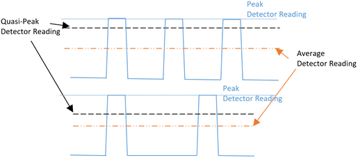
During the pre-compliance process, you scan your product for noise and compare it to limit lines described in required standards. The standards also specify how the noise needs to be detected. Most commercial standards use three major detectors defined by CISPR16-1: peak, quasi-peak and average. Peak detection, as its name indicates, retains the peak value to each harmonics of the signal, indicating the worst-case scenario. Average detection provides the amplitude of each signal component across its period, showing the best-case scenario. Quasi-peak detection weighs each component based on its periodicity: the faster repetition rate, the higher the weight.
The figure below shows the three detectors response to two similar pulsed signals, with the top one having a higher repetition rate. Notice the quasi-peak detector has a higher voltage output.

Notice that the quasi-peak detector has a higher voltage output.
To perform EMI scans quickly, most engineers start with peak detection in design and pre-compliance testing. The results are then compared against the published quasi-peak limits. If the design meets the quasi-peak limits, with lots of margin to spare, the product is likely to pass compliance, and quasi-peak testing may not be necessary. However, if the product marginally passes peak detection, quasi-peak testing is recommended. It is the same method used in compliance and will assist in identifying potential areas of concern.
Performing pre-compliance testing
Reproducing the exact same test conditions of the compliance procedure at your own location is nearly impossible, unless you are willing to spend lots of money on facilities and equipment. However, you can still increase the probability of passing EMI/EMC compliance testing by investing in a pre-compliance test solution that you can set up at, or near your location.
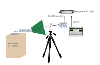
The ideal location for testing is in a radio free environment, far away from base stations or any radio-wave pollution. One suggestion is to set up radiated emission testing at an external site such as a large empty warehouse. The ideal setup avoids walls with hidden metal harnesses or objects that can create reflections and may null some of the faulty frequencies and/or amplify some “passing” ones. You will also need to invest in antennas, tripod and an amplifier in addition to a spectrum analyzer. For conducted emission test, you will need to invest in a good isolated table, an insolation transformer and a LISN.
The figure below shows a radiated test setup using a Tektronix RSA306B real-time USB spectrum analyzer.

Radiated test set-up with a Tektronix RSA306 real time USB spectrum analyzer.
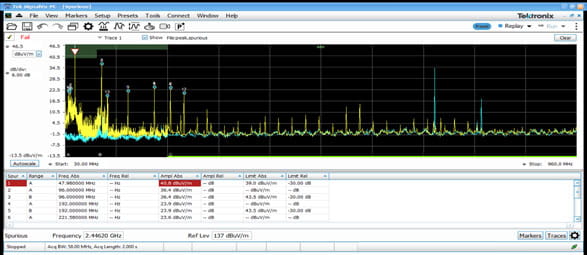
For radiated emission testing, the initial step is to scan the ambient environment with the device in position but turned off. The next scan or first scan for conducted emission should be using peak detection. As mentioned above, peak detection testing is fast and it gives a quick overall perspective of how far the noise amplitude is from the limit and which potential frequencies are a concern.
The screen capture below shows an ambient trace and a first peak scan compared to the limit line of FCC part 15 Class A up to 960 MHz. The ambient is captured as the teal trace and the peak scan is captured as the yellow trace. The table shows the results of peak scan versus the limit line. As you can see, the results show a large number of spurs in the A region as well as a failure.

The next scan to be captured uses quasi peak detector across region A (zoomed up to 59 MHz) to get more precise results and is more in line with the official testing done at an accredited test house.
The screen shot below shows the results for peak (green trace) and quasi peak (yellow trace) versus the limit line. In this example, the device is now passing with a margin of 1.5 dB. However, this is probably not enough to ensure passing at the test house. To account for inaccuracies introduced by the pre-compliance test setup, it is best to have more margin. Consultants recommend 10 dB of margin, if it is achievable.
In this case, the device will have to be modified to achieve more margin, before it is ready to be tested in the regulatory environment of an EMC/EMI test house.

The quasi-peak test shows that the devices barely passes and most likely will need to be modified.
Using a USB Real Time Spectrum Analyzer
For EMC/EMI pre-compliance testing, it is important to select a spectrum analyzer with software supporting quasi-peak, peak and average detection. During the course of designing and testing products, there are situations where you may need to use all three of these tests to get an accurate picture of your product’s ability to pass EMC/EMI compliance testing.
Tektronix offers a full line of USB real-time spectrum analyzers including the RSA306B, the RSA500 Series and RS600 Series to help you decide whether you are ready to go to the test house or not.
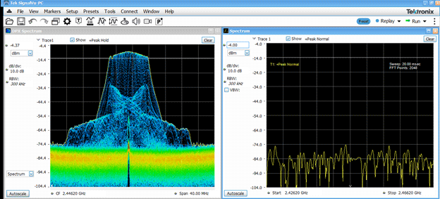
Comparison tests against swept spectrum analyzers have shown pre-compliance tests such as quasi-peak can be processed faster if you are using a USB real-time spectrum analyzer with a laptop, tablet or desktop computer. In addition, with a real-time spectrum analyzer such as the RSA306B, you can see failures hidden under broadband noise that swept spectrum analyzers are not be able to see. The figure below (on the right side) shows what a swept spectrum analyzer would likely see, once it is done sweeping 40 MHz versus a real-time spectrum analyzer (on the left).

Comparison of a real-time spectrum analyzer on the left with a swept spectrum analyzer.
Tektronix has much more information on how to greatly improve the probability of a successful first pass of full EMI compliance on our EMI/EMC applications page. And for more information about the new capabilities found in our real-time USB spectrum analyzer, visit our spectrum analyzers page.


