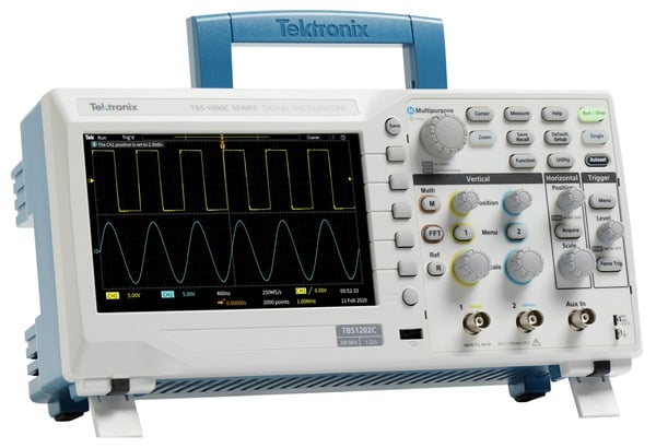

Though it’s not uncommon to measure current with a digital multimeter, measuring current that changes over time requires the use of an oscilloscope. Most oscilloscopes only directly measure voltage, not current, however you can measure current with an oscilloscope, using one of two methods.
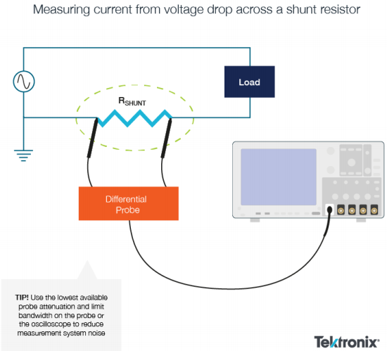
- Measure the voltage dropped across a shunt resistor: Some power supply designs may have shunt resistors built into the design for feedback. One technique is to measure the differential voltage drop across such a resistor. These are generally low-value resistors, often smaller than 1 Ohm.
- Measuring current with a current probe: When used in conjunction with an oscilloscope’s voltage measurements capabilities, current probes can enable a wide variety of important power measurements, such as instantaneous power, average power, and phase.
To make sure your current measurements are as accurate as possible, the most appropriate technique must be selected and applied correctly. Each of the above two methods has its advantages and disadvantages, which we’ll explore below.
How to measure current as a voltage drop across a shunt resistor
If a current sense resistor (“shunt” resistor) is designed into the DC power supply, this is the most convenient approach.
Measuring the voltage drop across the sense resistor with an active differential probe will provide good results, as long as the common-mode signal is within the probe’s specified operating range and the voltage drop is large enough.
However, using a differential probe on low-level signals requires some attention to noise reduction in the measurement system.
- Use the lowest available probe attenuation and limit bandwidth on the probe or the oscilloscope to reduce measurement system noise.
- Also, keep in mind that the probe’s capacitance and resistance will be in parallel with the sense resistor, and although they are designed to minimize the impact on the device under test, you should be aware that they exist.
Design considerations when measuring current with a shunt resistor
Introducing a sense resistor in series with the load requires careful design consideration. As the resistance value increases, the voltage drop per ampere increases according to Ohm’s Law, thus improving the quality of the current measurement. However, the power dissipation in the resistor increases with the square of the current and the additional voltage drop must be accounted for. In addition, resistors add inductive reactance to the circuit.
And don't forget that the differential probe input capacitance appears in parallel with the sense resistor, forming an RC filter.
If you do add a sense resistor to the circuit, try to add it as close to ground as possible to minimize the common mode signals across the resistor that the measurement system must reject. And, unlike high-performance current probes, the common-mode rejection performance of differential voltage measurements tends to fall off over frequency, reducing the accuracy of high-frequency current measurements with sense resistors.

How to measure current with a current probe
Current flow through a conductor causes an electromagnetic flux field to form around the conductor. Current probes are designed to sense the strength of this field and convert it to a corresponding voltage for measurement by an oscilloscope.
This allows you to view and analyze current waveforms with an oscilloscope. When used in combination with an oscilloscope’s voltage measurement capabilities, current probes also allow you to make a wide variety of power measurements. Depending on the waveform math capabilities of the oscilloscope, these measurements can include instantaneous power, true power, apparent power, and phase.
There are two primary types of current probes for oscilloscopes:
- AC current probes
- AC/DC current probes.
Read more: How to Measure Frequency with an Oscilloscope
The principle of transformer action
Both types use the principle of transformer action for sensing alternating current (AC) in a conductor.
For transformer action, there must be alternating current flow through a conductor. This alternating current causes a flux field to build and collapse according to the amplitude and direction of current flow. When a sensing coil is placed in this magnetic field, the changing flux field induces a proportional voltage across the coil through simple transformer action. This current-related voltage signal is then conditioned and can be displayed as a current-scaled waveform on an oscilloscope.
Types of current probes
The simplest AC current probes are passive devices which are simply a coil that has been wound to precise specifications on a magnetic core such as a ferrite material. Some are solid toroids and require the user to route the conductor through the core. Split-core current probes use a precisely designed mechanical system that allows the core to be opened and clamped around the conductor without breaking the circuit under test. Splitcore current probes are capable of high sensitivity and operate without power but are mechanically rigid and typically have a small aperture, which can limit their versatility.
AC current probes based on Rogowski coil technology, are an alternative to solid- and split- core current probes. The Rogowski coil uses an air core and is mechanically flexible, allowing the coil to be opened and wrapped around a wire or component lead. And, because the core is not a magnetic material, Rogowski coils do not magnetically saturate at high current levels, even thousands of Amps. However, they tend to have lower sensitivity than split-core probes, and they require active signal conditioners to integrate the signal from the coil, and thus require a power source.
For many power conversion applications, a split-core, AC/DC current probe is the most versatile, accurate and easy-to-use solution. AC/DC current probes use a transformer to measure AC currents and a Hall-Effect device to measure DC current. Since they include active electronics to support the Hall-Effect sensor, AC/DC probes require a power source to operate. This power source can be a separate power supply or may be integrated into some oscilloscopes.


