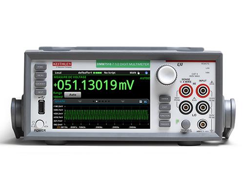
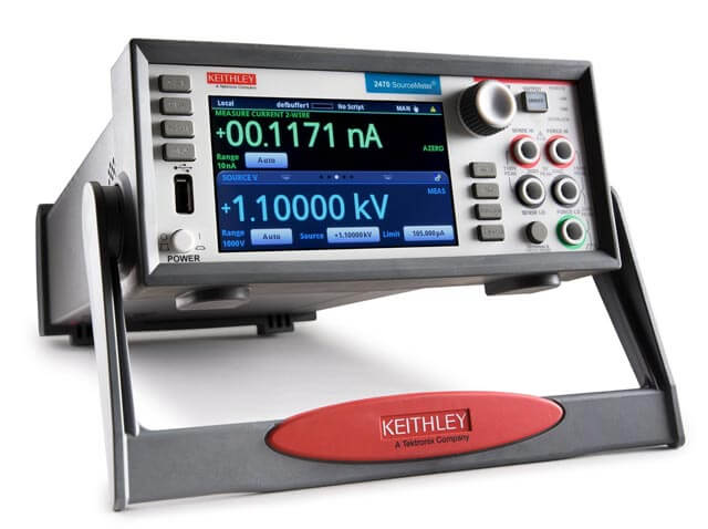
Contact us
Call us at 1-800-833-9200
Available 9 AM - 5 PM IST Business Days
Download
Download Manuals, Datasheets, Software and more:
Feedback
The Importance of EVSE Testing
Electric Vehicle Supply Equipment (EVSE), or commonly known as charging stations, are a critical component in the migration from internal combustion. The availability (uptime & reliability) of stations and the speed at which they can charge are major factors in the adoption of EVs.
EVSE must also comply with key EV charging standards such as IEC 61851 and SAE J1772.
At the device, module and system levels, engineers are working to reduce charging times with higher charging voltages, while improving reliability and maintaining safety. Smart, flexible testing solutions enable designers to quickly troubleshoot and validate their designs.
Solutions include a high-performance oscilloscope with sophisticated power analysis software and a high accuracy DMM for measurements of EVSE performance and a bidirectional power supply acting as a load that simulates a high voltage, high capacity, discharged battery.
View The Complete Bench SetupLearn how to:
- EVSE system - functional blocks
- Power Factor Correction (PFC) and AC/DC conversion testing
- DC/DC converter and gate driver analysis
- Control system and power management analysis
- Vehicle interface measurements and debugging
- User interface and network communications analysis
- Simulating the EV Battery
EVSE Test Equipment and Techniques

DC fast charging station block diagram
EVSE System - Functional Blocks
State-of-the-art DC fast-chargers convert 3-phase AC from the power grid to high-voltage DC. Systems are made up of:
- Power factor correction and AC/DC converter
- DC/DC converter
- Control systems and power management
- User interfaces
- LAN / cellular communications
- High voltage charging and communication vehicle port
Each of these blocks requires testing. Explore the solutions below to learn more.
Power Factor Correction (PFC) and AC/DC Conversion Testing
Chargers designed to connect to public utilities must limit the impact on the local grid or operators will be subjected to higher energy rates or penalties. Most utilities charge for power factor below 90 to 95% and many require compliance with harmonics standards.
The input stages of DC fast charging equipment are not only responsible for converting 3-phase AC to DC, but it must also ensure high power factor and low harmonic distortion, while maintaining high efficiency and reliability.
Oscilloscope-based systems with advanced power analysis software facilitate accurate, repeatable measurements, including:
- Line-side power quality
- Power Factor
- Harmonics
- Overvoltage/undervoltage protection
- Switching characteristics
- Timing (e.g. dead time)
- Dynamic switching loss
- Double-Pulse Testing
- Output ripple
- Efficiency

Power factor correction on the front end of chargers uses switching to align voltage and current for unity power factor. It also smooths current draw to reduce harmonic loading on the utility.
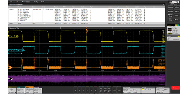
Detailed switching loss measurements quantify loss in FETs and IGBTs within power conversion circuits.
DC/DC Converter and Gate Driver Analysis
High power DC/DC converters provide isolation between the PFC block and voltage regulation for the vehicle charging port. High frequency transformers are often used for isolation and energy storage. New designs may use fast SiC MOSFETs to add efficiency and power density.
The fast switching speeds and voltage levels of SiC MOSFETS introduce measurement challenges due to high bandwidth and common mode voltages. EVSE test equipment solutions, including oscilloscopes with optically isolated probes and analysis software, Oscilloscopes with optically isolated probes and analysis software deliver accurate measurements even on high slew-rate, high common mode voltage signals. These include:
- Peak inrush current
- Overvoltage/undervoltage protection
- Switching analysis
- Miller duration and capacitance
- Gate resistance and charge parameters
- Dead time
- Switching loss
- In-circuit transformer and inductor measurements
- Control loop performance (e.g. PSRR and gain/phase margin)
- Ripple and noise
- EMI/EMC analysis
Control System and Power Management Analysis
Embedded controllers are the brains behind the charging process. During charging they handle communication with the vehicle, regulate power flow, and monitor safety conditions. They also communicate with the user interface and digital networks.
These subsystems typically include processors or FPGAs, clocks, power rails, memory systems, and communications ICs, often operating on GHz signals with low amplitude. Since these systems operate in harsh physical and electrical environments, they require high noise immunity and power integrity.
Key measurements for validating and debugging these systems include:
- Power rail ripple and noise analysis
- Impedance measurements
- Power supply sequencing
- AC-DC Converters
- Switching and Timing Analysis
- Dead time analysis between Low side and High side switches
- Magnetic analysis for Transformers and Inductors
- Control loop analysis
- Communications signal integrity
- EMI/EMC analysis
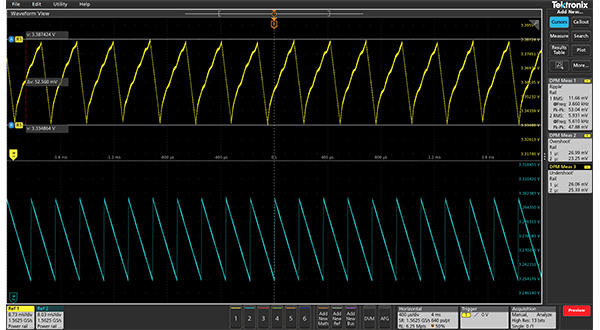
Ripple measurements quantify noise on power rails.
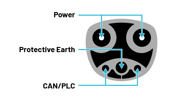
EV interfaces use two or more large pins for power and protective earth. Smaller pins are used for communication and may include control pilot (CP), proximity pilot (PP) or controller area network (CAN).
Vehicle Interface Measurements and Debugging
Reliable communication between the charging station and vehicle battery management system is critical to manage the charging process and maintain safety.
Chargers that comply with IEC61851 incorporate a control pilot (CP) signal. The duty cycle of the CP signal conveys the maximum available current from the EVSE to the EV. This signal can be verified using an oscilloscope. Power line communications (PLC) may also be superimposed on this line for communication during the charging process. Some interfaces rely on serial data carried over CAN for communication between the EVSE and EV.
In both cases oscilloscopes are invaluable for checking signal quality throughout the system, looking for attenuation, noise and incorrect termination. Most Tektronix oscilloscopes can be outfitted with CAN bus decoding and triggering to display transactions synchronized with other system level activity.
In addition to conducting data communication, the charging interface must maintain current and voltage within specified limits. For example, the charger must limit the impact of line voltage transients, surges and sags on the DC output to the vehicle to specified levels and durations.
Key measurements for validating and debugging EVSE, include:
- Communication signal integrity / noise
- Duty cycle of the DP signal
- System timing
- Noise on DC output
- Output regulation
User Interface and Network Communications Analysis
User interface devices often connect into the control system over standard serial buses such as RS-232, SPI or USB. Network communication provides key information for both charging station operators and users. Oscilloscopes and active probes are well-suited for signal and timing evaluation for user interface connections, LAN and wireless communications. Tektronix oscilloscopes support decoding on over 25 serial buses from RS-232 to wireless NFCs.
Key measurements include:
- Signal integrity / noise
- System timing
- CAN Bus decode
- LAN
- NFC decode
- Baseband RF
- EMI/EMC analysis
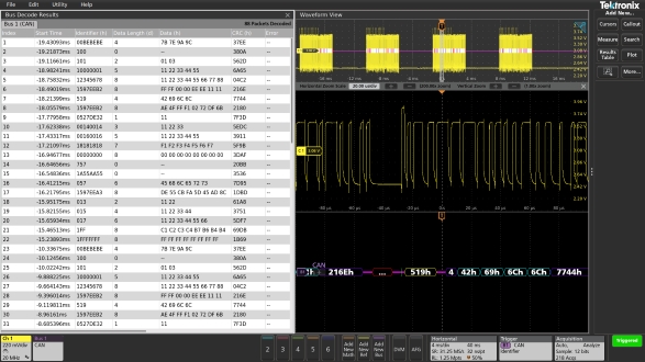
CAN bus decoding may be used to display communications between the charging station and the electric vehicle.
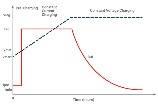
EV battery charge cycle which a bidirectional power supply must simulate.
Simulating the EV Battery
Testing an EVSE requires a load that can act like a discharged battery. Bidirectional power supplies can sink current at various voltage levels as well as source current to simulate a battery. The bidirectional power supply must draw a wide current range to simulate high charge current delivered to a discharged battery and low current delivered near the fully charged state. The supply must also have a voltage rating exceeding 800 V for charging to the increasing voltages of EV battery packs. As EV chargers support faster charging, the electronic loads used to test them must be able to handle more power.
High accuracy and stability enable stable and repeatable voltage and current levels to ensure all EVSEs are subjected to the same load conditions. Loads with fast rise and fall time allow for rigorous testing of the load regulation of chargers.
With the EVSE delivering high power, the power supply needs overvoltage, overcurrent, and overtemperature monitoring to ensure protection for the EVSE-under-test and the supply itself. EVSE tests are often performed under computer control, requiring a robust programming interface -- USB, Ethernet, CAN, RS-232 and EtherCAT interfaces are a few examples.
EVSE Testing Reference Solution
To guide you in creating an effective testing setup including an EA battery simulator tailored to your needs, we've included the table below. Here you'll find key instruments, probes, and options, along with their quantities and descriptions, each of which can be adjusted to suit your own individual requirements.
| Instrument/Probe/Option | Quantity | Description |
| EA 10000 Series | 1 | Bidirectional DC power supply and battery simulator |
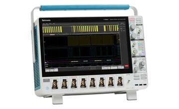
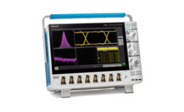
| MSO56B | 1 | 5 Series B MSO with 6 input channels |
| Opt. 5-BW-500 | 1 | 500 MHz bandwidth |
| Opt. 5-SRAUTO | 1 | CAN, CAN-FD, LIN, FlexRay bus decoding and triggering |
| Opt. 5-PWR | 1 | Power measurement and analysis |
| Opt. 5-SV-RFVT | 1 | Spectrum view RF vs. time traces and triggers for EMI/EMC troubleshooting |
| TCP0030A | 2 | Two current probes |
| TMDP0200 or THDP0200 | 2 | Two high voltage differential probes |
| TLP58 | 1 | 8-channel logic probe for protocol and mixed signal analysis |
| TPP0500B | 1 | Six passive voltage probes for voltage (included with oscilloscope) |
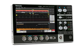
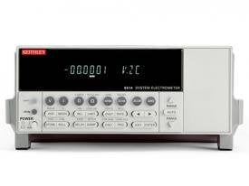
| Keithley DMM6500 | 1 | 6.5-digit multimeter for precision measurements |
Explore Our EVSE Test Equipment
Frequently Asked Questions
Why is communication testing between EV and EVSE systems important?
- Enhanced User Experience: Effective communication testing ensures that electric vehicles (EVs) and charging stations can interact seamlessly, providing EV owners with a smooth and hassle-free charging experience. This is critical for user satisfaction and trust in the charging infrastructure.
- Safety and Reliability: Communication testing helps detect and address potential safety issues and vulnerabilities in the charging system. By identifying and mitigating risks, it contributes to the overall safety and reliability of EV charging.
- Interoperability: Interoperability testing ensures that different EV models and charging stations can communicate effectively. This is pivotal for creating an open and accessible EV charging ecosystem where users can choose from various charging options.
- Standard Compliance: Many countries and regions have specific standards for communication protocols in EV charging. By adhering to these standards through testing, charging systems can meet regulatory requirements.
What are some common tests performed to verify power converters?
- Efficiency Testing: Power converters and PV inverters are tested for their efficiency, which assesses how effectively they convert electrical energy. High efficiency is essential for reducing energy waste and ensuring optimal system performance.
- Safety Checks: Safety testing evaluates power blocks for potential risks such as overheating, short circuits, or electrical faults. Ensuring the safety of these components is crucial for preventing accidents and system failures.
- Performance Validation: Performance testing assesses the power blocks' ability to operate under various conditions, including load variations and environmental factors. It helps ensure reliable and consistent performance.
- Electromagnetic Compatibility (EMC) Testing: EMC testing checks whether power blocks emit electromagnetic interference and are immune to external interference. Compliance with EMC standards is vital for trouble-free operation in the presence of other electronic devices.
- Temperature Profiling: Monitoring temperature is essential for preventing overheating, which can lead to component damage. Temperature profiling identifies potential thermal issues and helps maintain safe operation.
What are the applications of EVSE test equipment?
- Conformance Verification: EVSE test equipment is used to rigorously validate the conformance of electric vehicle supply equipment (EVSE) with international charging standards. This involves evaluating grid interaction, communication protocols, voltage levels and current levels, as well as compliance with safety standards.
- Interoperability Evaluation: The test equipment is also used to assess the compatibility between various EV models and charging stations. Interoperability testing is crucial to ensure seamless communication and reliable charging experiences for all users.
- Safety Assurance: Safety tests are conducted to test systems that protect users and equipment from shock or damage, including isolation, grounding and ground fault interrupters such as RCDs or GFCIs.
- Performance Optimization: EVSE test equipment aids in optimizing the performance of charging stations. Engineers utilize these tools to improve efficiency and reduce charging times, while ensuring safety and reliability.
How is EVSE testing equipment used in Research and Development?
During the EVSE design process engineers use test equipment to bring up and validate subsystems and the system as a whole:
- Simulate Various Charging Scenarios: The engineer would use the EVSE testing equipment to simulate various charging scenarios, mimicking different vehicle types and charging conditions.
- Monitor Communication: They would monitor the communication between the EVSE and the simulated vehicle, checking for any irregularities in the signal integrity or timing.
- Measure Power Output: The engineer would also measure the power output under different load conditions, ensuring that the EVSE can deliver the required power safely and efficiently.
- Debugging and Validation: Designers use test equipment during the design process to bring up prototypes and validate the performance of new products.
- Verify Reliability: Finally, engineers would verify that the charging station can reliably serve a wide range of electric vehicles under a variety of environmental conditions.
What are the typical measurements in the field of power electronics and EV systems?
- Voltage Measurements: Voltage measurements are essential for assessing the electrical potential within power electronics and EV systems. They provide insights into electrical circuits' behavior and ensure they operate within safe voltage limits.
- Current Measurements: Current measurements gauge the flow of electric charge within power electronics and EV systems. Accurate current measurements are crucial for monitoring power consumption and ensuring electrical components' safety.
- Temperature Monitoring: Temperature monitoring is vital for preventing overheating and ensuring the longevity of power electronics and battery systems in EVs. It helps maintain safe and efficient operation.
- Power Factor (PF) Analysis: Power factor measurements assess the efficiency of electrical power conversion within power electronics. A high power factor indicates efficient energy use, reducing waste and energy costs.
- Harmonics Analysis: Harmonics are unwanted distortions in electrical waveforms that can impact system performance. Harmonics analysis helps identify and mitigate these distortions to maintain power quality.
- Efficiency Measurements: Efficiency measurements evaluate how effectively power is converted and utilized within power electronics and EV systems. High efficiency is essential for reducing energy waste and operating cost-effectively.
- Voltage Ripple: Voltage ripple or fluctuations can affect the operation of sensitive electronics. Monitoring and minimizing ripples are important for ensuring stable and reliable system performance.
- State of Charge (SoC) Measurements: SoC measurements are particularly relevant for battery management in EVs. They determine the available energy in the battery, allowing for accurate range estimations and preventing over-discharge.
- DC Bus Voltage Measurements: Monitoring DC bus voltage ensures system stability and protects critical components, such as inverters and power converters. It is crucial for safe and reliable operation.
- Energy Consumption Monitoring: Measuring energy consumption provides insights into how efficiently energy is used, allowing for optimization and cost savings in EV and power electronics applications. It helps in managing power usage efficiently and identifying areas for improvement.
- Isolation Testing: Isolation testing ensures electrical safety and helps prevent electrical hazards. It confirms that circuits and components are properly isolated and free from potential faults, guaranteeing safe operation.


