Introduction
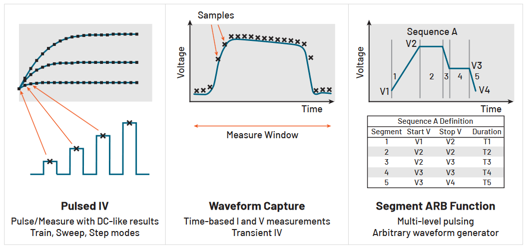
Ultra-fast IV sourcing and measuring is important to many semiconductor applications, including nonvolatile memory, power device characterization, CMOS, reliability and MEMS devices. These semiconductor tests are made using the Keithley 4225-PMU Pulse Measure Unit (PMU), a 2-channel high-speed voltage source and time-based current measurement module for the 4200A-SCS Parameter Analyzer. The PMU has three modes of ultra-fast IV source and measure modes: Pulse IV, Waveform Capture and Segment ARB™. These three modes are illustrated in Figure 1.
Using pulse IV signals to characterize devices instead of DC signals makes it possible to reduce the effects of selfheating or to minimize current drift. Waveform capture mode, or transient IV, outputs high-speed voltage pulses and measures the current and voltage response in the time domain. Pulsed sourcing, or Segment ARB, can be used to stress a device using an AC signal during reliability cycling or in a multi-level waveform mode to program and erase memory devices.
The easy-to-use interactive Clarius software comes with the 4200A-SCS and has a test library that includes many PMU applications. However, some PMU measurements may need to be part of an automated test controlled by an external computer. In these cases, remote control of the PMU is necessary.
The Keithley External Control Interface (KXCI) enables remote control of the instrument modules in the 4200A-SCS by sending commands from a computer. The controlling computer can be connected to the 4200A-SCS through GPIB or ethernet to remotely send the KXCI commands using a coding environment.
Starting with Clarius V1.13, KXCI commands for high-speed IV sourcing and measuring have been added to the Clarius software for remote controlling the PMU and the 4220-PGU Pulse Generator Unit (PGU). This enables test automation outside of the Clarius interface software. These commands, along with programming examples for each mode, are explained in this application note. Tables of PMU KXCI commands are listed in Appendix A and B at the end of this application note.
Getting Started Using KXCI
With the Keithley External Control Interface (KXCI), an external computer is used to directly control the SMUs, CVUs, PMUs and PGUs in the 4200A-SCS Parameter Analyzer. Each of the modules has its own command set and can be used to configure a variety of different tests.
The first step to using the KXCI software tool is to close the Clarius software and open the Keithley Configuration Tool (KCon), located on the desktop, and configure settings for either GPIB or ethernet communications. After these settings are configured, close KCon and open the KXCI application. Once you have KXCI opened, you can start sending commands to the modules in the 4200A-SCS. More detailed configuration information about using KXCI and the command sets for all the instruments are in the manual Model 4200A-SCS KXCI Remote Control Programming.
Basic information on getting started using KXCI with Python is in the application note Controlling the 4200A-SCS Parameter Analyzer Using KXCI and Python 3. This application note describes using Visual Studio code with Python 3 and NI VISA to control the 4200A-SCS using KXCI commands.
Examples of Ultra-Fast IV: Pulse IV, Waveform Capture and Segment ARB
This section includes KXCI programming examples of the three modes of ultra-fast IV: Pulse IV, Waveform Capture and Segment ARB.
Pulse IV
Pulse IV refers to any test with a pulsed voltage source and a corresponding high-speed, time-based current measurement that provides DC-like results. The voltage and current measurements are an average, or spot mean, of readings taken in a predefined measurement window on the pulse. The user defines the parameters of the pulse, including the pulse width, period, rise/fall times and amplitude.
The following pulse IV programming example generates an IV sweep on a 1 kohm resistor. As illustrated in Figure 2, one end of the resistor is connected to the center conductor of the coax cable (HI) of PMU CH1 and the other side of the resistor is connected to PMU common (LO), or the outside shield of the coax cable.

Part of a Python script to create a pulse IV sweep is shown in Figure 3. The code includes the amplitude sweep parameters (including start V = −5 V, stop V = 5 V, step size = 0.1 V and base V = 0 V) and the pulse timing parameters (period = 10e−6 s, pulse width = 5e −6 s, rise and fall times = 1e −7 s).
Other defined parameters include the measure window and the measure range. The measure window command (:PMU:TIMES:PIV) is the percent range on the pulse top where the average, or spot mean, is derived. In this example, the measure window is between 0.75 and 0.9 of the top of the pulse. For each pulse, one reading is derived. The current measure range (:PMU:MEASURE:RANGE) is fixed at 10 mA, but autorange or limited autorange can also be used. Using autorange enables the PMU to find the best current range and is useful for devices that have a large change in current during a voltage sweep, such as a diode.
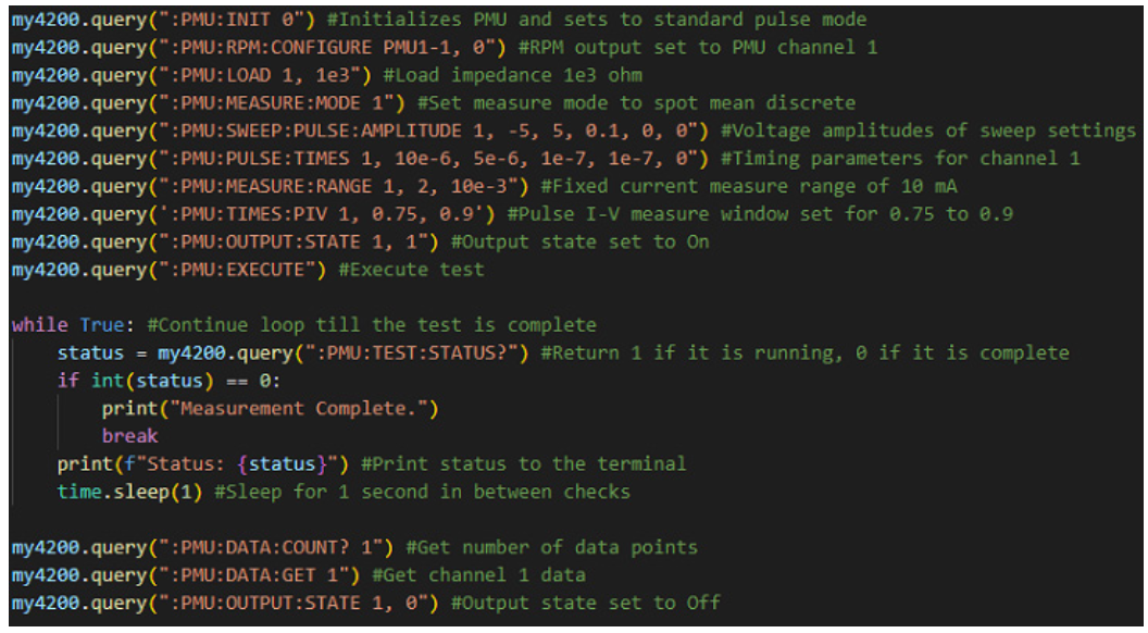
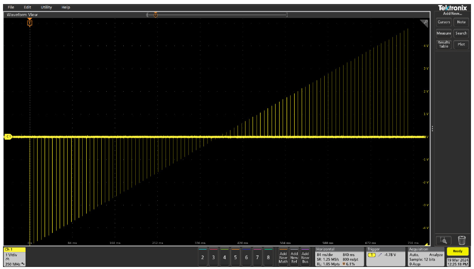
Once the code is executed, the PMU outputs a pulse IV sweep from −5 V to 5 V in 0.1 mV steps. Figure 4 shows the scope capture from the Tektronix MSO5 Series Oscilloscope of the 101 pulses in the sweep. Only the spot mean of each of these pulses is derived and used in the IV measurement of the resistor.
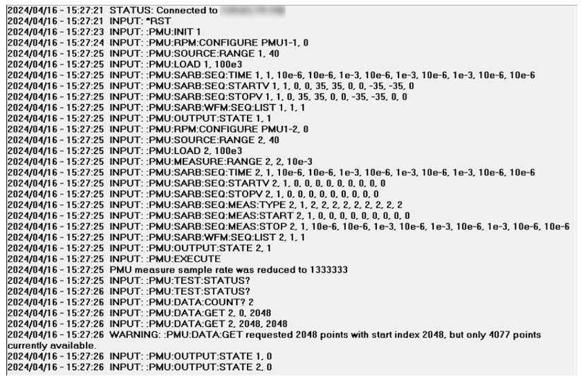
Once the code is executed using the :PMU:EXECUTE command, all the commands sent to the PMU are logged in the KXCI console, as shown in Figure 5, along with any messages or errors. Also listed in the KXCI console are the commands sent that are used to retrieve the data. The :PMU:TEST:STATUS? command determines if the sweep is finished executing. The :PMU:DATA:COUNT? command is used to determine how many readings are stored in the data buffer. Finally, the :PMU:DATA:GET command retrieves the data from the buffer.

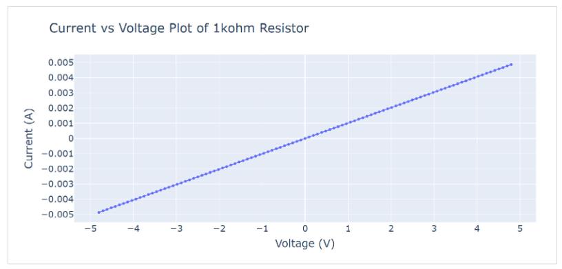
Once the data is retrieved, the current can be plotted as a function of voltage using any plotting tool, as shown in Figure 6. This plot was created by an additional Python tool that allows for visualization of the data return. Notice there is one point plotted for each point in the sweep.
Waveform Capture
The waveform capture, or transient IV, mode outputs high speed voltage pulses and measures the resulting current and voltage transients in the time domain.
The next example uses the waveform capture mode of the PMU to show the time-based response of the drain current and drain voltage of a MOSFET. Figure 7 shows the connections between the two channels of the PMU to the three terminals of the MOSFET. CH1 outputs a single 2 V pulse to the gate. CH2 outputs a 1 V pulse to the drain and captures the transient response of the drain current and voltage. The source terminal of the MOSFET is connected to Common or the outside shell of the coax cable.
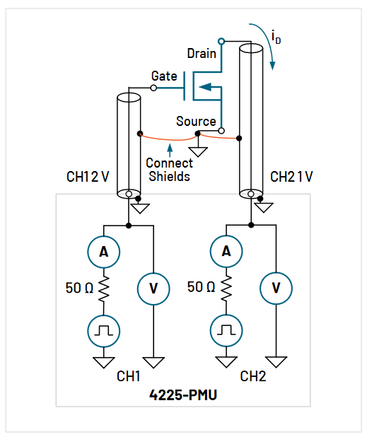
Python code that outputs voltage pulses on PMU CH1 (gate) and PMU CH2 (drain) and measures the resulting drain current and voltage on PMU CH2 is shown in Figure 8. In this example, both channels are connected to the device, so they both need to be configured. However, commands to configure measurements are only sent to PMU CH2, since only PMU CH2 will return data.
The :PMU:PULSE:TRAIN command configures the pulse base and amplitude voltage for each channel. In this case, CH1 outputs a single 2 V pulse and CH2 outputs a 1 V pulse. The :PMU:PULSE:TIMES command sets the timing parameters on each channel (period = 1e-6 s, pulse width = 5e-7 s, rise and fall times = 1e-7 s and delay time = 1e-7 s).
The measurements are made with the Load Line Effect Compensation (LLEC) feature enabled (:PMU:LLEC:CONFIGURE 2, 1) on CH2. LLEC employs a mathematical algorithm that compensates for the voltage drop across the 50 ohm output impedance of the PMU and the voltage drop across the lead resistance and connections to the DUT.
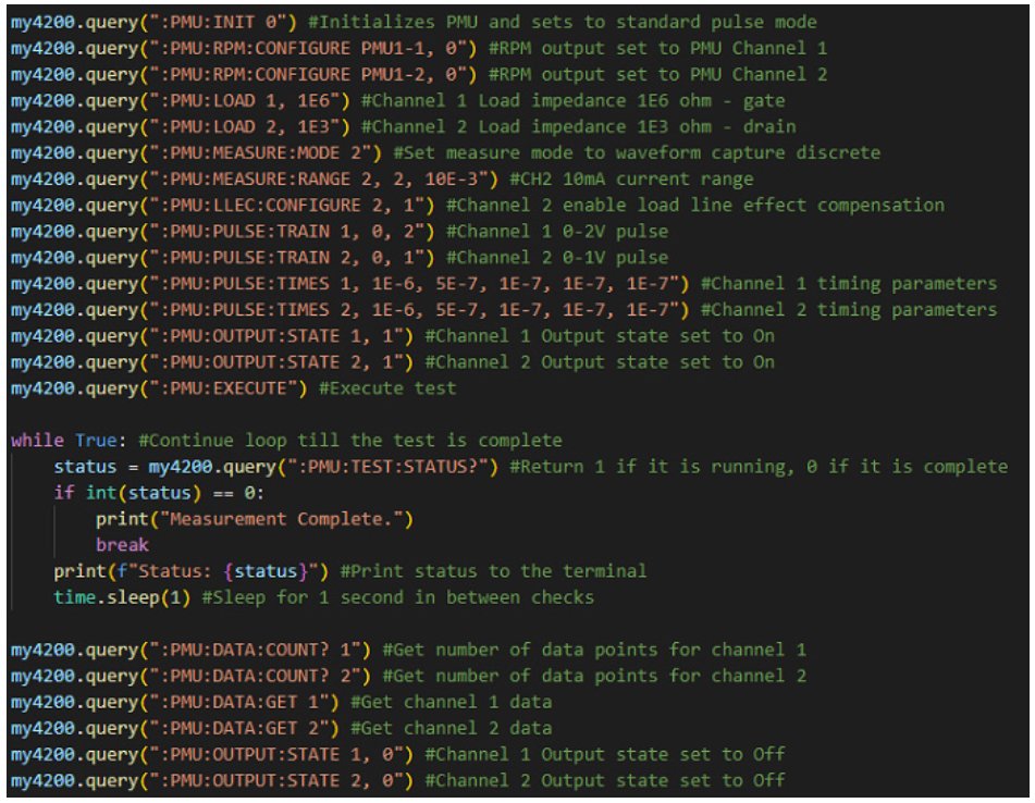
Once the :PMU:EXECUTE command is used to start the test, you can use the :PMU:TEST:STATUS? command to check if the test finished. In waveform capture mode, the test will return the voltage, current, time and status from each channel that was configured to make measurements, in this case, CH2. Figure 9 shows the transient drain voltage and current of the MOSFET.

Segment ARB Waveform
Each channel of the PMU can be configured to output its own Segment ARB waveform composed of user-defined line segments, up to 2048. There are separate commands for time interval, start and stop voltage values, start and stop measure window values, output trigger and output relay state (open or closed). Each command defines that parameter for all the segments in the waveform. Both spot mean and sample mode measurements are supported for each segment.
Segment ARB sequences are constructed using the :PMU:SARB commands, which are listed in Appendix B. The :PMU:SARB commands define all parts of each segment, such as the start voltage, stop voltage, time and measure type. For example, the time of every segment is defined sequentially using the :PMU:SARB:SEQ:TIME command and the starting voltages of each segment are defined by the PMU:SARB:SEQ:STARTV command. The use of these commands is demonstrated in the following example.
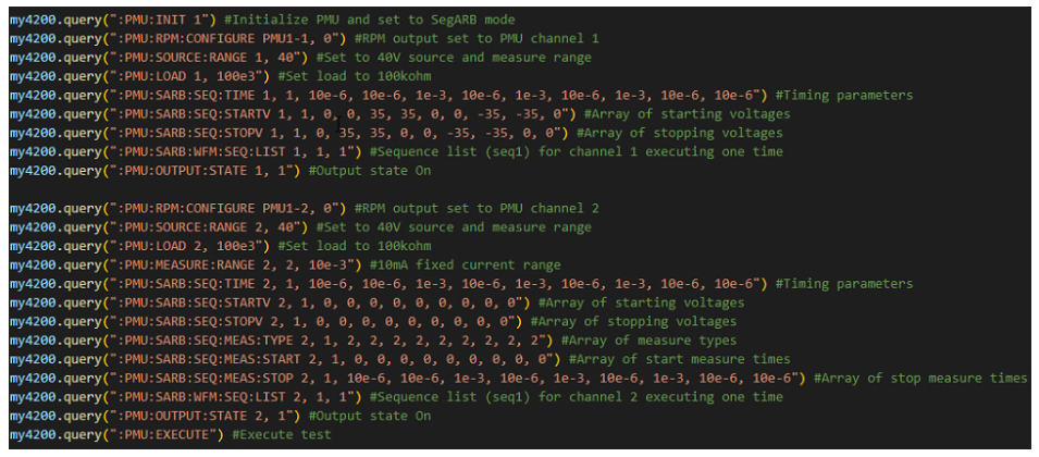
This example will output a Segment ARB sequence that sources a 35 V, 1e-3 s pulse and then a −35 V, 1e −3 s pulse on PMU CH1. PMU CH2 forces 0 V and measures the resulting current and voltage. The circuit diagram is shown in Figure 10.

Forcing voltage on one side of the resistor and measuring current on the other side is called the lowside measurement technique and is used for ultra-fast high impedance measurements. This technique avoids errors due to leakage current and longer settling time. Further information on this method can be found in the Keithley application note, Making Low Current Pulse I-V Measurements with the 4225-PMU Pulse Measure Unit and 4225-RPM Remote/Preamplifier Switch Modules.
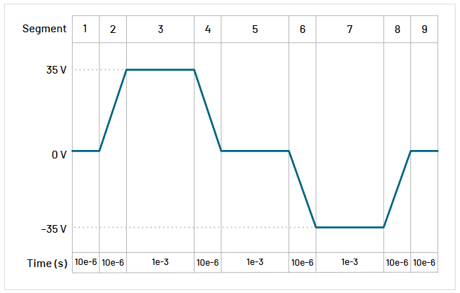
PMU CH1 is configured to output the Segment ARB sequence shown in Figure 11. (NOTE: The timing axis is not to scale.) This sequence has nine segments that generate a +35 V pulse for 1e-3 s and then a −35 V pulse for 1e−3 s. There are 1e−3 s segments for rise and fall times. Each of the nine segments has a unique time, start voltage and stop voltage, as configured by the following commands:
| Parameter | Command (CH1, Sequence 1) |
| Time | :PMU:SARB:TIME: 1, 1, 10e-6, 10e-6, 1e-3, 10e-6, 1e-3, 10e-6, 1e-3, 10e-6, 10e-6 |
| Start Voltage | :PMU:SARB:SEQ:STARTV 1, 1, 0, 0, 35, 35, 0, 0, -35, -35, 0 |
| Stop Voltage | :PMU:SARB:SEQ:STOPV 1, 1, 0, 35, 35, 0, 0, -35, -35, 0, 0 |
PMU CH1 is configured to output only. PMU CH2 is configured to force 0 V and measure the waveform capture current and voltage on each segment. The start and stop measure times are also configured on CH2. The Python code used to control CH1 and CH2 is listed in Figure 12.
Once the code is executed, the commands are logged in the KXCI console, as shown in Figure 13.
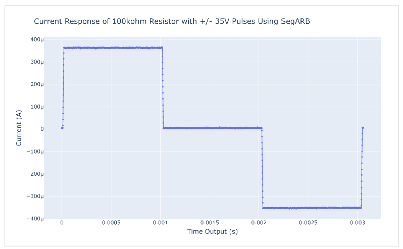
The resulting current measurements of the 100 kohm resistor measured by CH2 are shown in Figure 14.
Conclusion
PMU KXCI commands enable automation of ultra-fast IV measurements for pulse IV, waveform capture and Segment ARB modes of operation. The PMU is controlled either through ethernet or GPIB connections using an external computer. Several example Python programs using the PMU KXCI commands are available on the Tektronix GitHub site.
Appendix A. Pulse IV and Waveform Capture Commands
| Command | Description |
| :PMU:ABORT | Aborts the present process running on a PGU and PMU. |
| :PMU:CONNECTION:COMP | Sets the type of PMU compensation and enables the compensation values. |
| :PMU:DATA:COUNT? | Determines how many readings are stored in the data buffer. |
| :PMU:DATA:GET | Gets real-time data, block by block (up to 2048 pts per block). |
| :PMU:EXECUTE | Runs a final verification, clears the data buffers and executes the configured pulse test. |
| :PMU:INIT | Resets the pulse card to default conditions and to either pulse mode or Segment ARB mode. |
| :PMU:LLEC:CONFIGURE | Enables or disables load line effect compensation. |
| :PMU:LOAD | Sets the output impedance. |
| :PMU:MEASURE:CONNECTION:COMP | Acquires short or current offset compensation data. |
| :PMU:MEASURE:MODE | Sets the measurement to spot mean or waveform capture and to either discrete or average modes. |
| :PMU:MEASURE:PIV | Chooses the readings to be returned in pulse IV mode. |
| :PMU:MEASURE:RANGE | Sets the current measure range type (autorange, limited autorange, or fixed range) and sets the range for limited and fixed range. |
| :PMU:OUTPUT:STATE | Sets the output state for the specified channel: Off or on. |
| :PMU:PULSE:BURST:COUNT | Defines the total number of pulses used in average or discrete modes with either spot mean or waveform measurements. |
| :PMU:PULSE:TIMES | Sets the pulse timing parameters: Period, width, rise time, fall time and delay. |
| :PMU:PULSE:TRAIN | Configures the base and amplitude voltage levels of the pulse. |
| :PMU:RETAIN:CONFIG | Retains the configured pulse settings without executing the test. This allows the :PMU:EXECUTE command to be repeatedly sent without sending all the PMU setting commands each time. |
| :PMU:RPM:CONFIGURE | Switches the RPM output between the PMU, CVU and SMU. |
| :PMU:SAMPLE:RATE | Selects the sample rate from 1E3 to 200E6 samples/s. |
| :PMU:SOURCE:RANGE | Sets both the force and measure voltage range to either 10 V or 40 V. |
| :PMU:STEP:DC | Configures the start, stop and step size of a DC voltage step. A DC voltage sweep must be configured on another channel. |
| :PMU:STEP:PULSE:AMPLITUDE | Configures the start, stop and step size of a pulse amplitude step with a fixed base. A DC voltage sweep must be configured on another channel. |
| :PMU:STEP:PULSE:BASE | Configures the start, stop and step size of a pulse base step with a fixed amplitude. A DC voltage sweep must be configured on another channel. |
| :PMU:SWEEP:DC | Configures the start, stop and step size of a DC voltage sweep. |
| :PMU:SWEEP:PULSE:AMPLITUDE | Configures the start, stop and step size of a pulsed voltage amplitude sweep with a fixed base. |
| :PMU:SWEEP:PULSE:BASE | Configures the start, stop and step size of a pulsed base sweep with a fixed amplitude. |
| :PMU:TEST:STATUS? | Determines if test is running or idle. |
| :PMU:TIMES:PIV | Defines the spot mean measurement window for pulse IV mode. |
| :PMU:TIMES:WAVEFORM | Defines measurement windows for pre and post pulse measurements in waveform capture mode. |
Appendix B. Segment ARB Commands
| Command | Description |
| :PMU:SARB:SEQ:MEAS:START | Defines an array of start measurement times for a Segment ARB sequence. |
| :PMU:SARB:SEQ:MEAS:START:ADD | Adds an additional array of start measurement times for a Segment ARB sequence. |
| :PMU:SARB:SEQ:MEAS:STOP | Defines an array of stop measurement times for a Segment ARB sequence. |
| :PMU:SARB:SEQ:MEAS:STOP:ADD | Adds an additional array of stop measurement times for a Segment ARB sequence. |
| :PMU:SARB:SEQ:MEAS:TYPE | Defines an array of measure types for a Segment ARB sequence. |
| :PMU:SARB:SEQ:MEAS:TYPE:ADD | Adds an additional array of measure types for a Segment ARB sequence. |
| :PMU:SARB:SEQ:SSR | Defines an array of values to control the high endurance output relay (HEOR). |
| :PMU:SARB:SEQ:SSR:ADD | Adds an additional array of values to control the high endurance output relay (HEOR). |
| :PMU:SARB:SEQ:STARTV | Defines an array of starting voltage levels for a Segment ARB sequence. |
| :PMU:SARB:SEQ:STARTV:ADD | Adds an additional array of starting voltage levels for a Segment ARB sequence. |
| :PMU:SARB:SEQ:STOPV | Defines an array of stopping voltage levels for a Segment ARB sequence. |
| :PMU:SARB:SEQ:STOPV:ADD | Adds an additional array of stopping voltage levels for a Segment ARB sequence. |
| :PMU:SARB:SEQ:TIME | Defines an array of segment times for a Segment ARB sequence. |
| :PMU:SARB:SEQ:TIME:ADD | Adds an additional array of segment times for a Segment ARB sequence. |
| :PMU:SARB:SEQ:TRIG | Defines an array of trigger values for the trigger output of a Segment ARB sequence. |
| :PMU:SARB:SEQ:TRIG:ADD | Adds an additional array of trigger values for the trigger output of a Segment ARB sequence. |
| :PMU:SARB:WFM:SEQ:LIST | Defines the Segment ARB waveform pulsemeasure sequence list. |
| :PMU:SARB:WFM:SEQ:LIST:ADD | Adds additional values for the Segment ARB waveform pulsemeasure sequence list. |
Find more valuable resources at TEK.COM
Copyright © Tektronix. All rights reserved. Tektronix products are covered by U.S. and foreign patents, issued and pending. Information in this publication supersedes that in all previously published material. Specification and price change privileges reserved. TEKTRONIX and TEK are registered trademarks of Tektronix, Inc. All other trade names referenced are the service marks, trademarks or registered trademarks of their respective companies.
051424 1KW-74070-0