Contact us
Call us at 1-800-833-9200
Available 6:00 AM – 5:00 PM (PST) Business Days
Download
Download Manuals, Datasheets, Software and more:
Feedback
Serial Triggering and Analysis
3 Series MDO, 4/5/6 Series MSO Applications Datasheet
More Information
- Product Support
- 4 Series B MSO Mixed Signal Oscilloscope
- 5 Series MSO Low Profile
- 5 Series B MSO
- 6 Series B MSO
- 3 Series MDO Mixed Domain Oscilloscope
- 6 Series Low Profile Digitizer
- Explore more Software models
Read Online:

On a serial bus, a single signal often includes address, control, data, and clock information. This can make isolating events of interest difficult. Optional serial applications transform the oscilloscope into a robust tool for debugging serial buses with automatic decode and analysis for I2C, SPI, eSPI, CAN, CAN FD, CAN XL, LIN, FlexRay, 10BASE-T1S, 100BASE-T1, SENT, RS-232/422/485, UART, USB 2.0, USB 3.0, USB 3.1 Gen 1, USB 3.2 Gen 1, Ethernet, I3C, SPMI, Spacewire, 8b10b, NFC, NRZ, MIL-STD-1553, ARINC 429, I2S, LJ, RJ, PCIe Gen 1/Gen 2/Gen 3, PSI5, CPHY, CXPI, DPHY, SMBus, 1-WIRE, EtherCAT, and TDM.
Key features
Automated Serial Decode and Analysis Options for I2C, SPI, eSPI, I3C 1, CAN, CAN FD, CAN XL, LIN, FlexRay, SENT1, RS-232/422/485, UART, USB 2.0, USB 3.0, USB 3.1 Gen 1, USB 3.2 Gen 1, Ethernet1, SPMI1, MIL-STD-1553, ARINC 429, I2S, LJ, RJ, PSI5, PCIe Gen 1/Gen 2/Gen 3, DPHY, CXPI, CPHY, SMBus, 1-WIRE, EtherCAT, and TDM
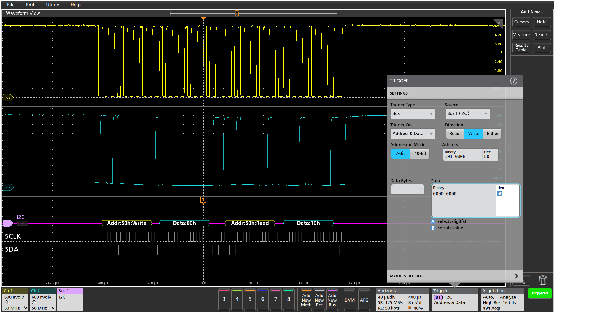
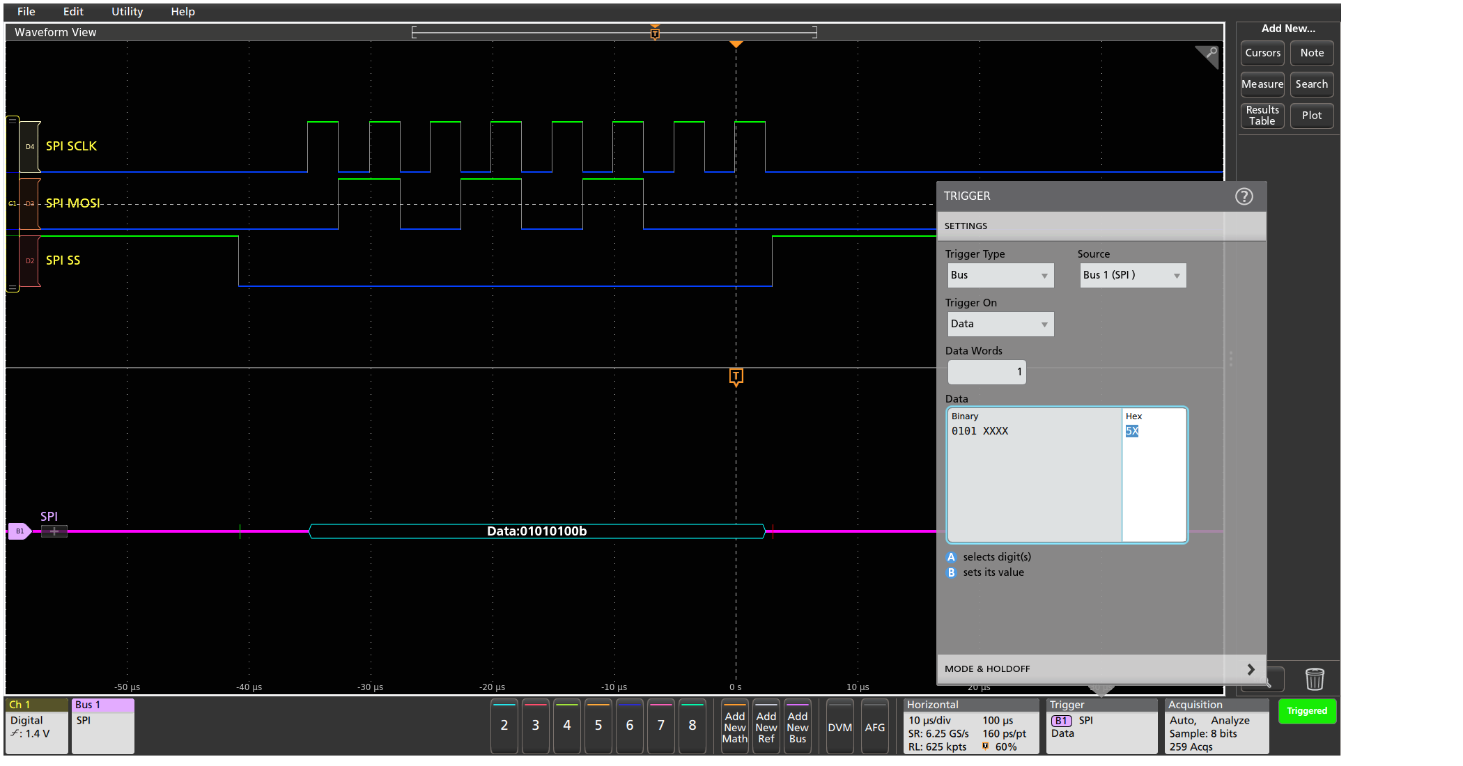
- Trigger on all the critical elements of a serial bus such as address, data, etc.
- Decode all the critical elements of each message. No more counting 1s and 0s
- Search through long acquisitions with user-defined criteria to find specific messages
- Event Table shows decoded serial bus activity in a tabular, time-stamped format for quick summary of system activity
Serial Triggering and Analysis Applications
The serial applications support automatic trigger and decode for I2C, SPI, CAN, CAN FD, CAN XL, LIN, FlexRay, 10BASE-T1S, 100BASE-T1, SENT, RS-232/422/485, UART, USB 2.0, USB 3.0, USB 3.1 Gen 1, USB 3.2 Gen 1, Ethernet, I3C, SPMI, Spacewire, 8b10b, NRZ, MIL-STD-1553, ARINC 429, I2S, LJ, RJ, PCIe Gen 1/Gen 2/Gen 3, PSI5, SMBus, EtherCAT, and TDM buses, making it easier to locate, analyze, and debug events of interest.
Serial triggering
Trigger on packet content such as start of packet, specific addresses, specific data content, unique identifiers, etc. on popular serial interfaces such as I2C, SPI, CAN, CAN FD, CAN XL, LIN, FlexRay, SENT, RS-232/422/485, UART, USB 2.0, USB 3.0, USB 3.1 Gen 1, USB 3.2 Gen 1, Ethernet, I3C, SPMI, MIL-STD-1553, ARINC 429, I2S, LJ, RJ, PCIe Gen 1/Gen 2/Gen 3, PSI5, and TDM.
Bus display
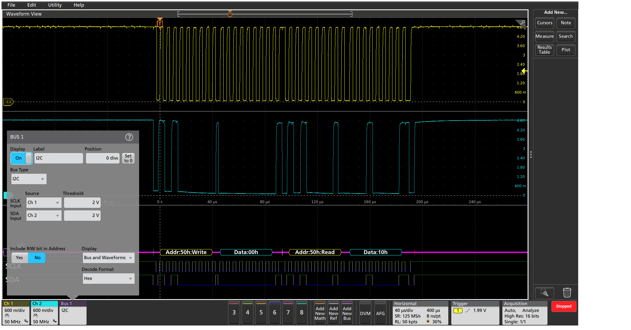
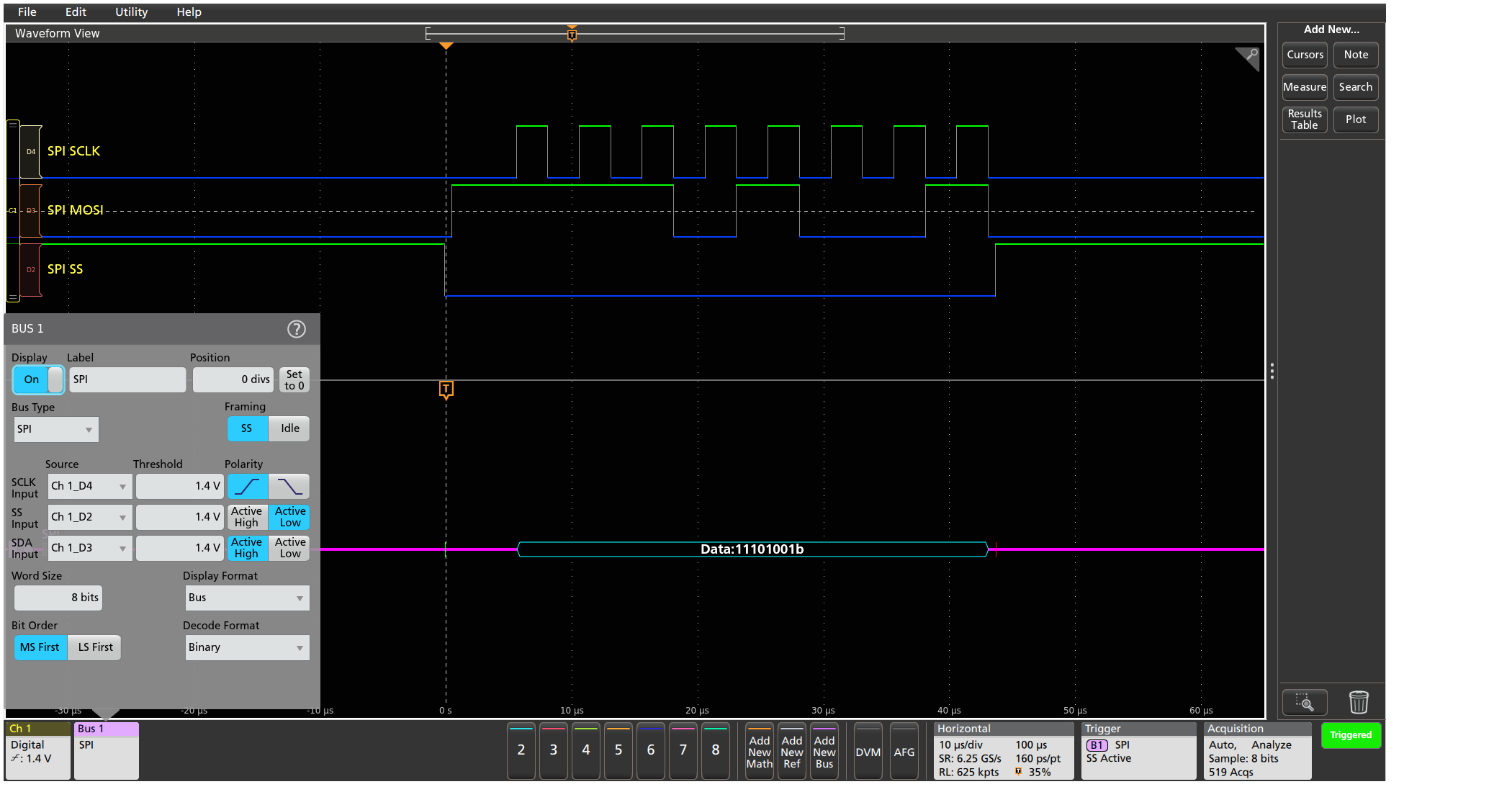
The bus display provides a higher-level, combined view of the individual signals (clock, data, chip enable, and so on) that make up your bus, making it easy to identify where packets begin and end and identifying sub-packet components such as address, data, errors, and so on.
Bus decoding
Tired of having to visually inspect the waveform to count clocks, determine if each bit is a 1 or a 0, combine bits into bytes, and determine the hex value?
Let the oscilloscope with a serial application do it for you! Once you've set up a bus, the oscilloscope decodes each packet on the bus, and displays the value in hex, binary, ASCII, or decimal (certain buses only) in the bus waveform.
Results table
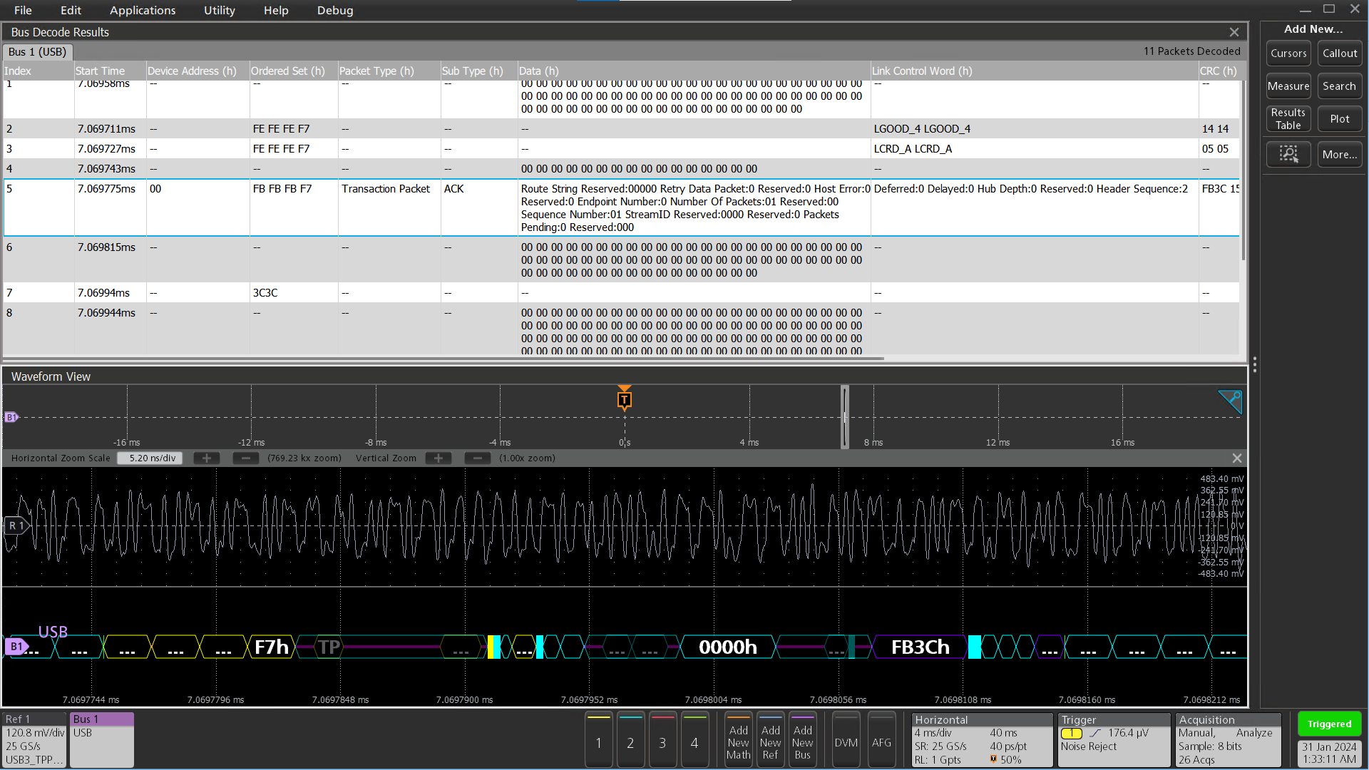
In addition to seeing decoded packet data on the bus waveform itself, you can view all captured packets in a tabular view much like you would see in a software listing. Packets are time stamped and listed consecutively with columns for each component (Address, Data, and so on).
Wave Inspector® search
Serial triggering is very useful for isolating the event of interest, but once you've captured it and need to analyze the surrounding data, what do you do?
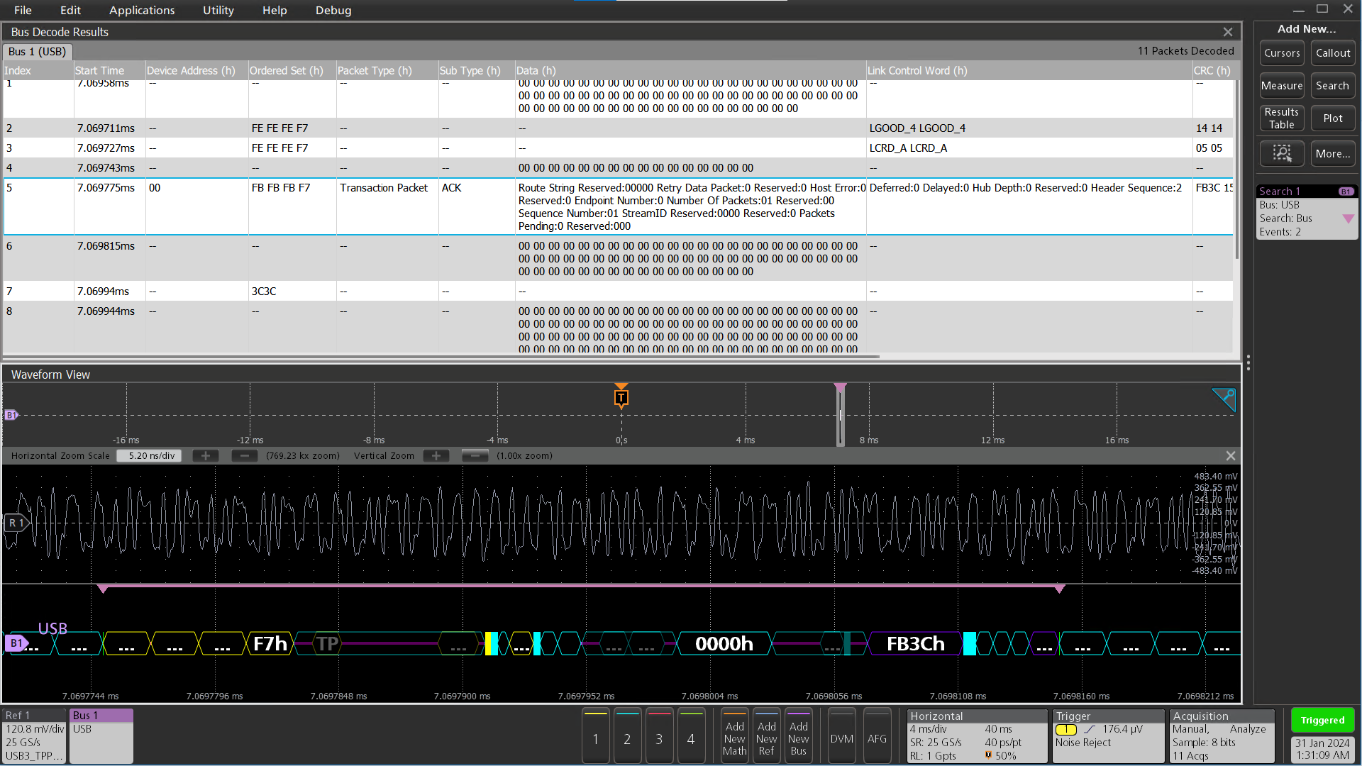
In the past, users had to manually scroll through the waveform counting and converting bits and looking for what caused the event. With a serial application, you can enable the oscilloscope to automatically search through the acquired data for user-defined criteria including serial packet content. Each occurrence is highlighted by a search mark. Rapid navigation between marks is as simple as pressing the ← and → arrow buttons on the oscilloscope front panel or the Search badge. The 3 Series MDO uses the arrows in the Search badge to navigate.
I2C characteristics
| Characteristic | Description |
|---|---|
I2C Sources (Clock and Data) | Analog channels Digital channels Active Math channels1 Active Reference channels1 |
| Thresholds | Per-channel thresholds |
| Recommended Probing | Single-ended |
| Include R/W in Address | Yes or No |
| Address/Data Formats Available | Hex Binary |
| Characteristic | Description |
|---|---|
| Bus | Bus only |
| Bus and Waveforms | Simultaneous display of bus and digital waveforms |
| Results Table | Decoded packet data in a tabular view |
| Characteristic | Description |
|---|---|
| Trigger and/or Search On | Start Repeated Start Stop Missing Ack Address (7 or 10 bit) Data (1-5 bytes) Address and Data |
| Characteristic | Description |
|---|---|
| Maximum Clock/Data Rate | Up to 10 Mb/s (automatic selection) |
| Decode Display | Start (green bar) Address (yellow packet) Data (cyan packet) Missing Ack (! symbol in red box) Stop (red bar) |
SPI characteristics
| Characteristic | Description |
|---|---|
| SPI Sources
(Clock, Data, and Slave Select) | Analog channels Digital channels Active Math channels1 Active Reference channels1 |
| Thresholds | Per-channel thresholds |
| Recommended Probing | Single-ended |
| Decode Configuration:
Framing Clock Slave Select Data Word Size Bit Order | Slave Select (3-wire SPI), Idle Time (2-wire SPI) Rising or Falling Edge Active High or Active Low Active High or Active Low 4 - 32 bits Most Significant (MS) First, Least Significant (LS) First |
| Formats Available | Hex Binary |
| Characteristic | Description |
|---|---|
| Bus | Bus only |
| Bus and Waveforms | Simultaneous display of bus and digital waveforms |
| Results Table | Decoded packet data in a tabular view |
| Characteristic | Description |
|---|---|
| Trigger and/or Search On | SS Active (3-wire SPI) Start of Frame (2-wire SPI) Data (1-16 bytes) |
| Characteristic | Description |
|---|---|
| Maximum Clock/Data Rate | Up to 10 Mb/s (automatic selection) |
| Decode Display | Start (green bar) Data (cyan packet) Stop (red bar) |
I3C characteristics1
| Characteristic | Description |
|---|---|
I3C Sources (Clock and Data) | Analog channels Digital channels Active Math channels Active Reference channels |
Thresholds | Per-channel thresholds |
Speed | High Speed (480 Mb/s) Full Speed (12 Mb/s) Low Speed (1.5 Mb/s) |
Recommended Probing | Single-ended |
Formats Available | Hex Binary Mixed Hex |
| Version | 1.0 1.1 |
| Characteristic | Description |
|---|---|
Bus | Bus only |
Bus and Waveforms | Simultaneous display of bus and digital waveforms |
Results Table | Decoded packet data in a tabular view |
| Characteristic | Description |
|---|---|
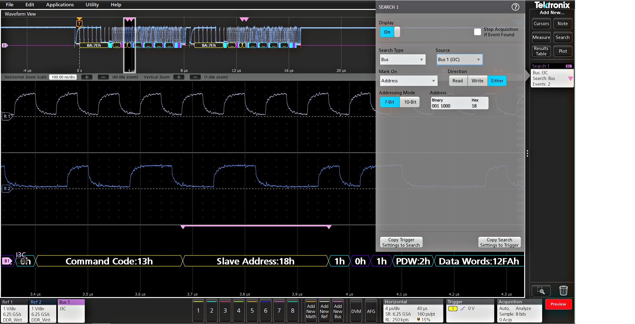
Search On | Start Repeated Start Address Data I3C SDR Direct Message I3C SDR Broadcast Message I3C DDR Message Errors Hot-Join Direct Message End Stop HDR Restart HDR Exit |
| Characteristic | Description |
|---|---|
| Maximum Clock/Data Rate | Up to 12.5 Mb/s (automatic selection) |
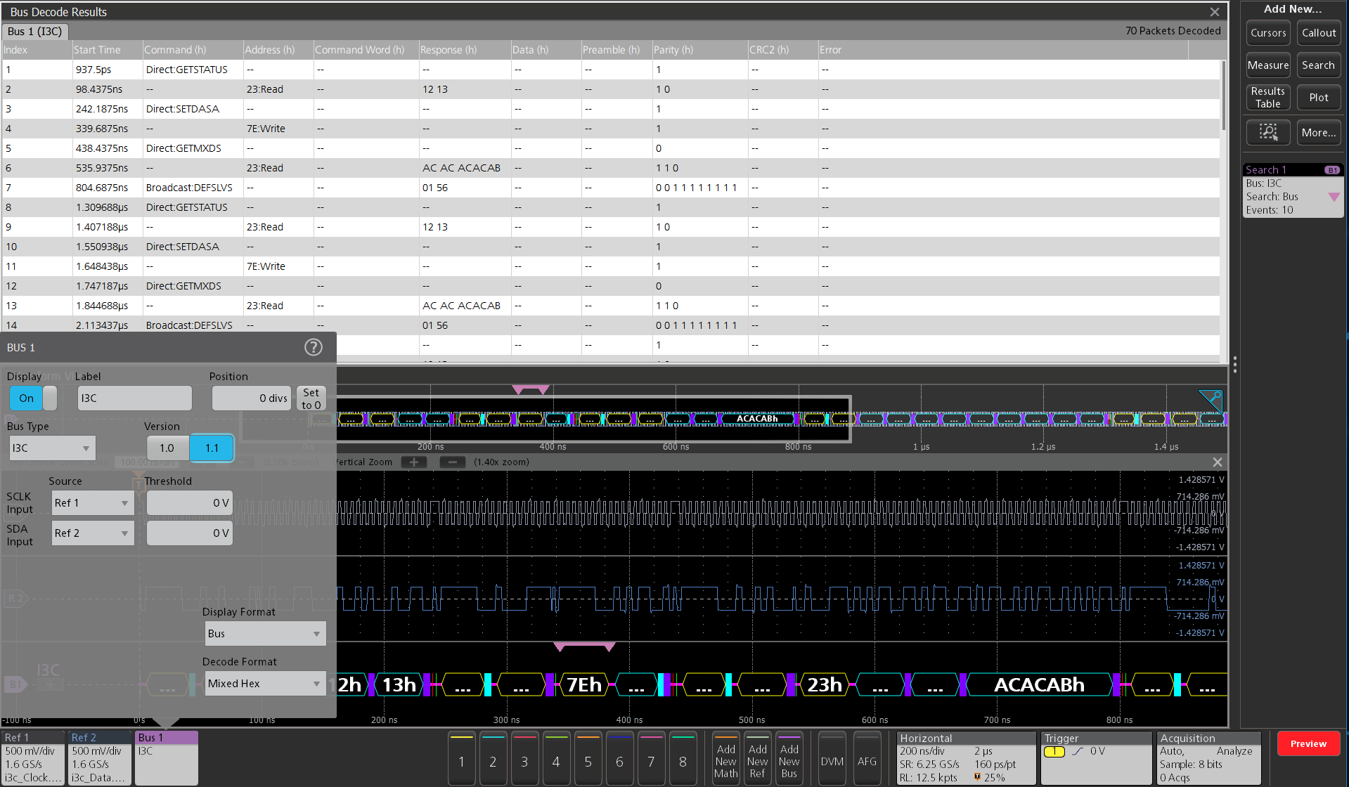
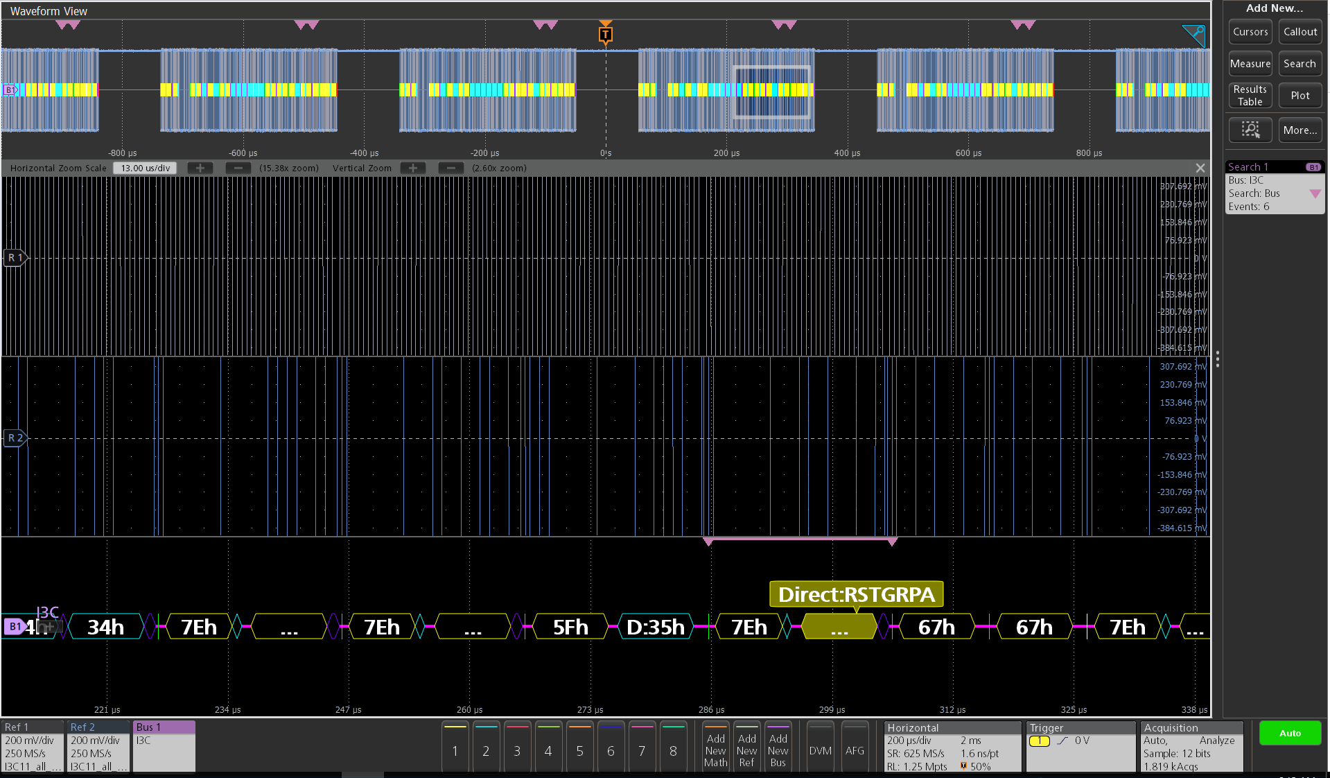
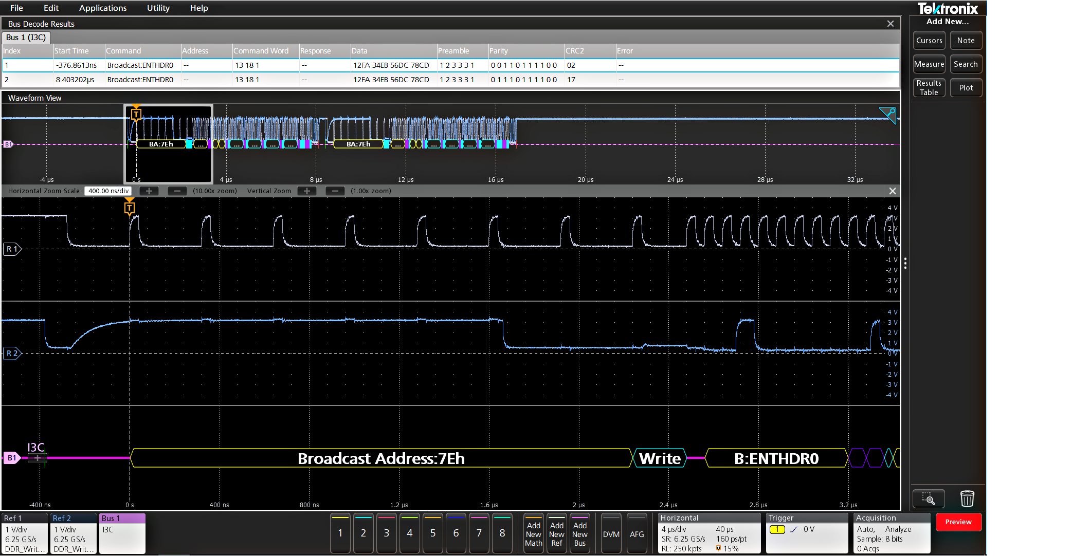
| Decode Display | Start (green bar) Address (yellow packet) Commands (cyan packet) Data (cyan packet) Parity (purple packet) Stop (red bar) |
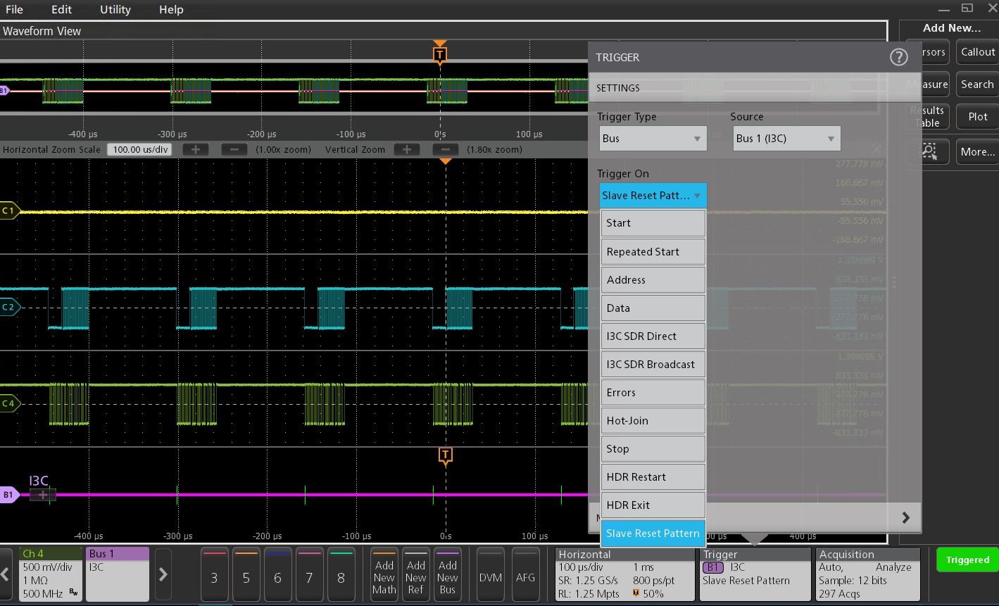
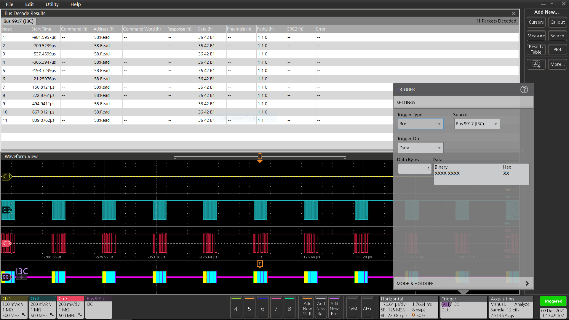
I3C (Trigger) characteristics
| Characteristic | Description |
|---|---|
| I3C Sources |
|
| Trigger On |
|
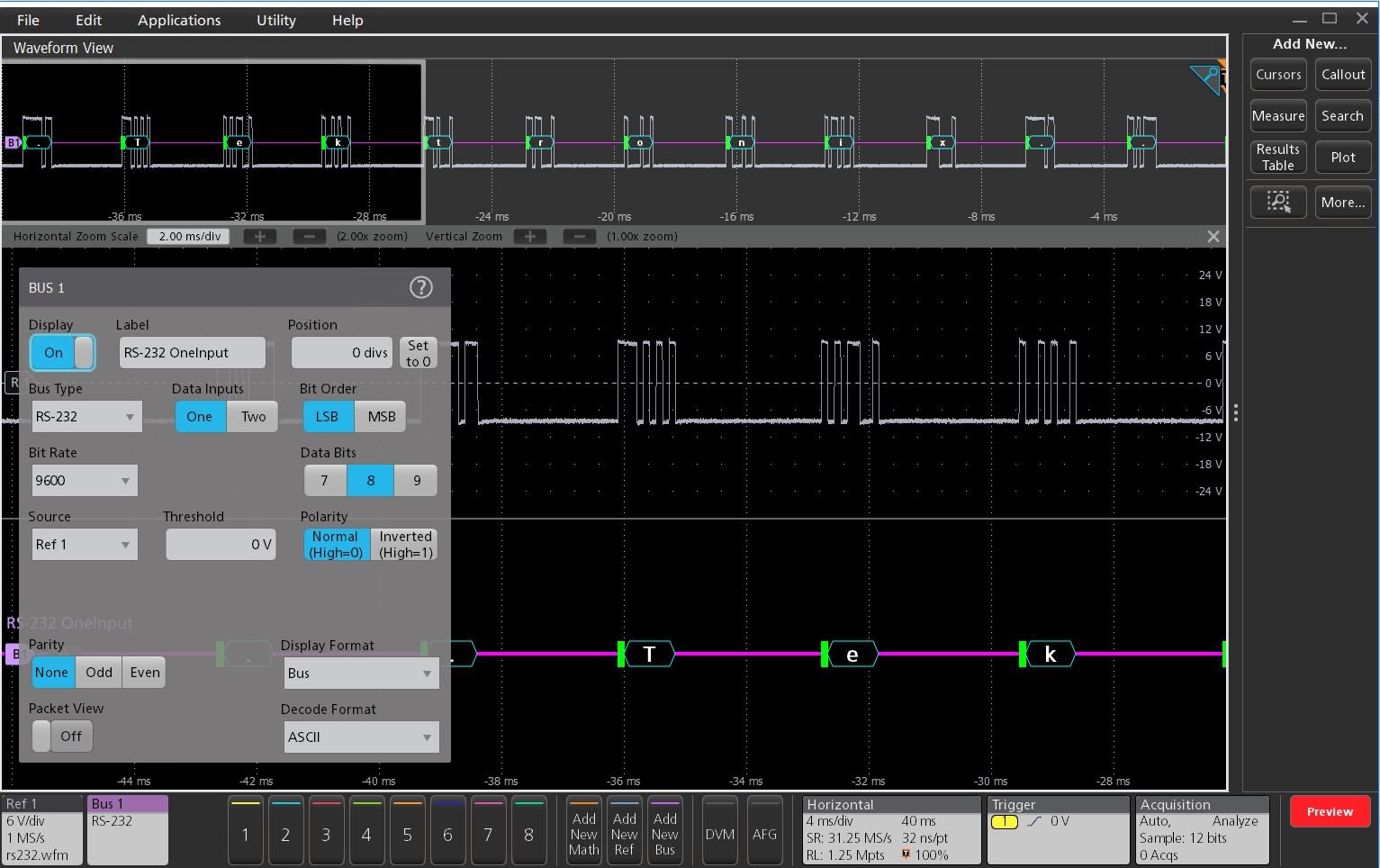
RS-232, RS-422, RS-485, UART characteristics
| Characteristic | Description |
|---|---|
| Sources, RS-232, UART | Analog channels Digital channels Active Math channels1 Active Reference channels1 |
| Sources, RS-422, RS-485 | Analog channels Active Math channels1 Active Reference channels1 |
| Polarity | Normal (RS-232) Inverted (UART, RS-422, RS-485) |
| Parity | None Odd Even |
| Recommended Probing, RS-232, UART | Single-ended |
| Recommended Probing, RS-422, RS-485 | Differential |
| Number of Bits | 7 - 9 |
| Formats Available | Hex Binary ASCII Packet View |
| Data Inputs | One, Two |
| Bit Order | MSB, LSB |
| Characteristic | Description |
|---|---|
| Bus | Bus only |
| Bus and Waveforms | Simultaneous display of bus and digital waveforms |
| Results Table | Decoded packet data in a tabular view |
| Characteristic | Description |
|---|---|
| Trigger and/or Search On | Start End of Packet Data (1 - 10 bytes) Parity Error |
| Characteristic | Description |
|---|---|
| Maximum Clock/Data Rate | Up to 15 Mb/s
For 3 Series MDO: Up to 10 Mb/s |
| Bit Rate Selection | 300 b/s 1,200 b/s 2,400 b/s 9,600 b/s 19,200 b/s 38,400 b/s 115,200 b/s 921,600 b/s Custom (All but 3 Series MDO: 50 b/s - 15 Mb/s Custom (for 3 Series MDO): 50 b/s - 10 Mb/s |
| Decode Display | Start (green packet) Data (cyan packet) Parity (purple packet) Parity Error (red packet) |

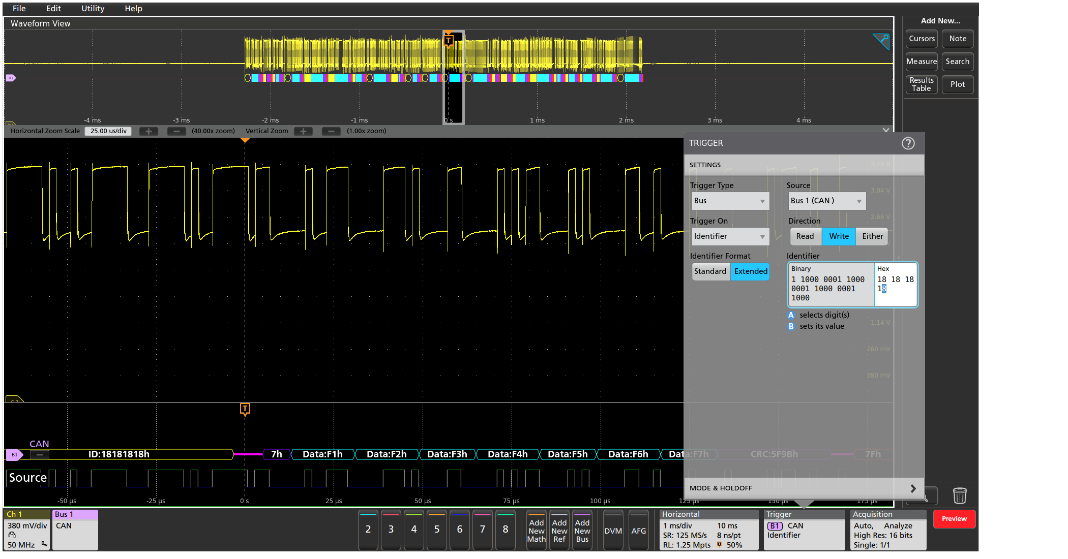
CAN characteristics (Version 2.0)
| Characteristic | Description |
|---|---|
| Source for CAN_H, CAN_L, Rx, or Tx (single-ended probing) | Analog channels Digital channels Active Math channels1 Active Reference channels1 |
| Source for Diff
(differential probing) | Analog channels Active Math channels1 Active Reference channels1 |
| Thresholds | Per-channel thresholds |
| Recommended Probing:
CAN_H, CAN_L, Rx, Tx Diff | Single-ended Differential |
| Bit Rate Selection:
Predefined list of rates Custom | 10 kb/s - 1 Mb/s All but 3 Series MDO: 1 kb/s - 1 Mb/s 3 Series MDO: 10 kb/s - 1 Mb/s |
| Sample Point | All but 3 Series MDO: 0% - 100% of bit period of unit interval 3 Series MDO: 5% - 95% of bit period of unit interval |
| Formats Available | Mixed Hex Hex Binary Symbolic (.dbc)1 |
| Characteristic | Description |
|---|---|
Bus | Bus only |
Bus and Waveforms | Simultaneous display of bus and digital waveforms |
Results Table | Decoded packet data in a tabular view |
| Characteristic | Description |
|---|---|
Trigger and/or Search On | Start of Frame Type of Frame (Data, Remote, Error, Overload) Identifier (Standard or Extended) Data (number of bytes 1-8, trigger or search when =, ≠, <, ≤, >, ≥) Identifier and Data EOF Missing Ack Bit Stuff Error |
| Characteristic | Description |
|---|---|
Message | As defined by the .dbc file1 |
Message and Signal | As defined by the .dbc file1 |
| Characteristic | Description |
|---|---|
| Maximum Clock/Data Rate | Up to 1 Mb/s (automatic selection) |
| Decode Display | Start of Frame (green bar) Identifier (yellow packet) Data Length Control (purple packet) Data (cyan packet) CRC (purple packet) End of Frame (red bar) Errors (red packet) |

CAN XL characteristics
| Characteristic | Description | ||
|---|---|---|---|
| Source for CAN_H, CAN_L, Rx, or Tx (Single-ended probing) | Analog channels Digital channels Active Math channels Active Reference channels | ||
| Source for Diff (Differential probing) | Analog channels Active Math channels Active Reference channels | ||
| Thresholds | Per-channel thresholds | ||
| Recommended Probing: | |||
| CAN_H, CAN_L, Rx, Tx Diff | Single-ended Differential | ||
| Nominal Bit Rate Selection: | |||
| Predefined list of rates Custom | 10 kb/s - 1 Mb/s 50 kb/s - 1 Mb/s | ||
| XL Bit Rate Selection: | |||
| Predefined list of rates Custom | 1 Mb/s - 20 Mb/s 500 kb/s - 20 Mb/s | ||
| Sample Point | 55% - 95% of bit period of unit interval | ||
| Formats Available | Mixed Hex Hex Binary |
| Characteristic | Description |
|---|---|
| Trigger On | Start of Frame End of Error |
| Search On | Start of Frame Type of Frame (XL Data Frame) Priority Identifier Data (1 byte) XL Bits (Acceptance Field, Virtual CAN Network ID, SDU Type, Simple Extended Content, Stuff Bit Count, Arbitration to Data Sequence, Data to Arbitration Sequence) ADS Type (Arbitration to Data High Bit, Data High Bit 1, Data High Bit 2, Data Low Bit) DAS Type (DAH, Active High 1, Active High 2, Active Low 1) End of Frame Error (Missing Ack, XL Form Error, CRC, Any Error) CRC Type (PCRC, FCRC) |
| Characteristic | Description |
|---|---|
| Decode Display | Start of Frame (green bar) Priority Identifier (cyan packet) Remote Request Substitute (cyan packet) FD Format Indicator (cyan packet) XL Format Indicator (cyan packet) Reserved Bit XL Format (cyan packet) XL Bits (cyan packet) Data Length Control (purple packet) PCRC (purple packet) Data (cyan packet) FCRC (purple packet) FCP (purple packet) Ack (cyan packet) Ack Delimiter (cyan packet) End of Frame (Dark pink packet) Errors (red packet) |
| Search On | Start of Frame Type of Frame (XL Data Frame) Priority Identifier Data (1 byte) XL Bits (Acceptance Field, Virtual CAN Network ID, SDU Type, Simple Extended Content, Stuff Bit Count, Arbitration to Data Sequence, Data to Arbitration Sequence) ADS Type (Arbitration to Data High Bit, Data High Bit 1, Data High Bit 2, Data Low Bit) DAS Type (DAH, Active High 1, Active High 2, Active Low 1) End of Frame Error (Missing Ack, XL Form Error, CRC, Any Error) CRC Type (PCRC, FCRC) |
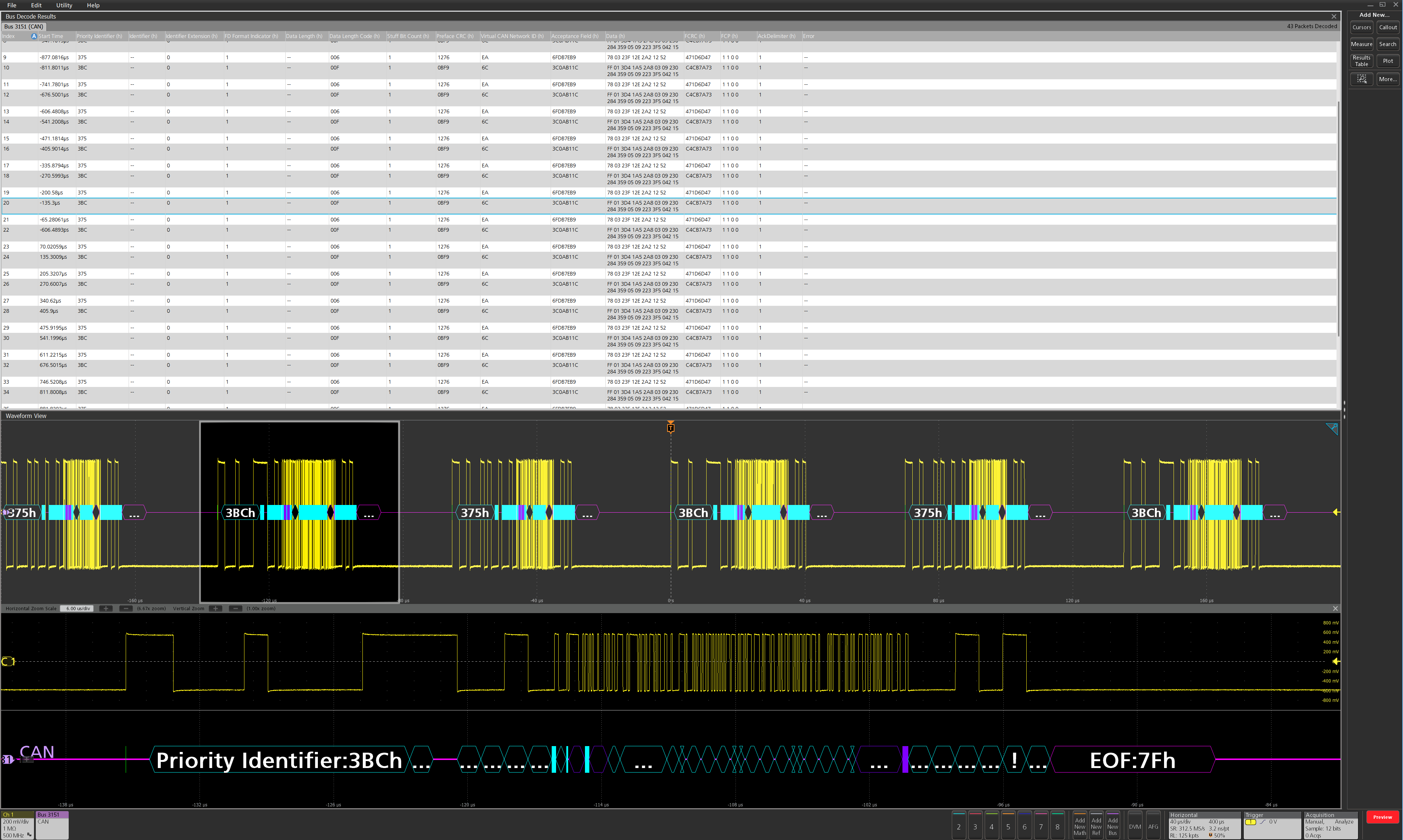

CAN FD (ISO and non-ISO) characteristics
| Characteristic | Description |
|---|---|
| Source for CAN_H, CAN_L, Rx, or Tx (single-ended probing) | Analog channels Digital channels Active Math channels 1 Active Reference channels1 |
| Source for Diff (differential probing) | Analog channels Active Math channels1 Active Reference channels1 |
| Thresholds | Per-channel thresholds |
| Recommended Probing: CAN_H, CAN_L, Rx, or Tx Diff | Single -ended Differential |
| Version | ISO non-ISO |
| SD Bit Rate Selection: Predefined list of rates Custom | 10 kb/s - 1 Mb/s All but 3 Series MDO: 50 kb/s - 10 Mb/s 3 Series MDO: 10 kb/s - 1 Mb/s |
FD Bit Rate Selection: Predefined list of rates Custom | All but 3 Series MDO: 1 Mb/s - 16 Mb/s 3 Series MDO: 1 Mb/s - 7 Mb/s All but 3 Series MDO: 500 kb/s - 16 Mb/s 3 Series MDO: 500 kb/s - 7 Mb/s |
Sample Point | All but 3 Series MDO: 55% - 95% of bit period of unit interval 3 Series MDO: 15% - 95% of bit period of unit interval |
Formats Available | Mixed Hex Hex Binary Symbolic (.dbc)1 |
| Characteristic | Description |
|---|---|
| Bus | Bus only |
| Bus and Waveforms | Simultaneous display of bus and digital waveforms |
| Results Table | Decoded packet data in a tabular view |
| Characteristic | Description |
|---|---|
Trigger and/or Search On | Start of Frame Type of Frame (Data, Remote, Error, Overload) FD Bits (Bit Rate Switch bit, Error State Indicator bit) Identifier (Standard or Extended) Data (1-8 bytes, trigger or search when =, ≠, <, ≤, >, ≥) Identifier and Data End of Frame Error (Missing Ack, Bit Stuffing Error, FD Form Error, Any Error) |
| Characteristic | Description |
|---|---|
| Message | As defined by the .dbc file1 |
| Message and Signal | As defined by the .dbc file1 |
| Characteristic | Description |
|---|---|
| Decode Display | Start of Frame (green bar) Identifier (yellow packet) Data Length Control (purple packet) Data (cyan packet) CRC (purple packet) End of Frame (red bar) Errors (red packet) |
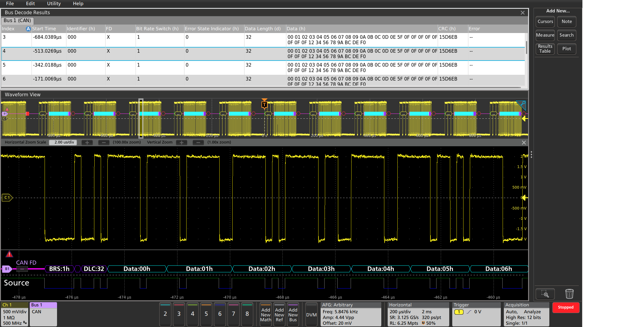
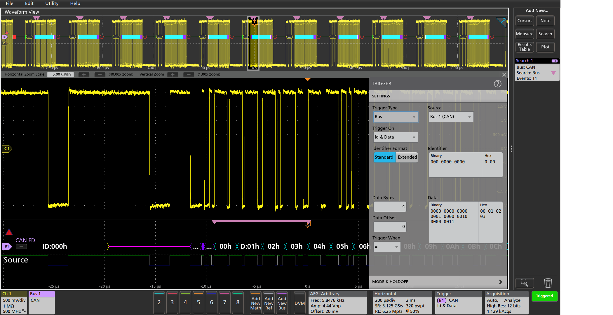
LIN characteristics (Version 2.0)
| Characteristic | Description |
|---|---|
| LIN Source | Analog channels Digital channels Active Math channels1 Active Reference channels1 |
| Thresholds | Per-channel thresholds |
| Recommended Probing | Single-ended |
| Polarity | Normal Inverted |
| Bit Rate Selection: Predefined list of rates Custom | 1.2 kb/s - 19.2 kb/s All but 3 Series MDO: 1 kb/s - 100 kb/s 3 Series MDO: 800 b/s - 100 kb/s |
| Sample Point | All but 3 Series MDO: 0% - 100% of bit period of unit interval 3 Series MDO: 10% - 90% of bit period of unit interval |
| LIN Standard | V 1.x V 2.x Both |
| Include Parity Bits with ID | Yes No |
| Formats Available | Hex Binary Mixed |
| Characteristic | Description |
|---|---|
| Bus | Bus only |
| Bus and Waveforms | Simultaneous display of bus and digital waveforms |
| Results Table | Decoded packet data in a tabular view |
| Characteristic | Description |
|---|---|
| Trigger and/or Search On | Sync Identifier Data (number of bytes 1-8, trigger or search when =, ≠, <, ≤, >, ≥, Inside Range, Outside Range) ID and Data Wakeup Frame Sleep Frame Error (Sync, ID Parity, Checksum) |
| Characteristic | Description |
|---|---|
| Maximum Clock/Data Rate | Up to 100 kb/s, by LIN definition up to 20 kb/s (for automated decoding of bus) |
| Decode Display | Start of Frame (green bar) Sync Identifier (yellow packet) Data (cyan packet) CRC (purple packet) Errors (red packet) |
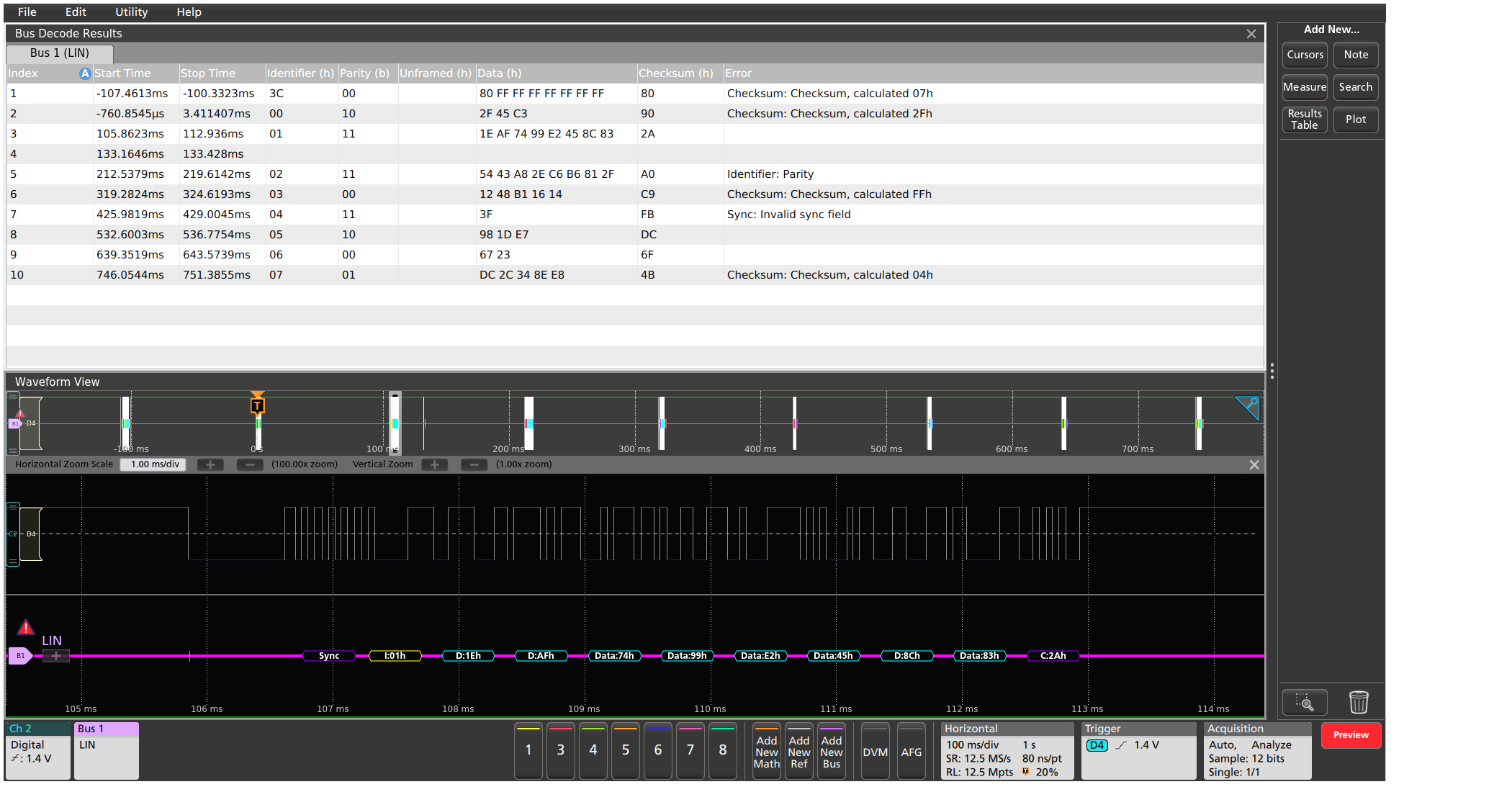

FlexRay characteristics (Version 2.0)
| Characteristic | Description |
|---|---|
| Source for Differential Probing (Bdiff) | Analog channels Active Math channels1 Active Reference channels1 |
| Source for Single-ended Probing (BP, BM) | Analog channels Digital channels Active Math channels1 Active Reference channels1 |
| Source for Single-ended Probing (Tx, Rx) | Analog channels Digital channels Active Math channels1 Active Reference channels1 |
| Thresholds: Bdiff BP, BM (analog channels) BP, BM (digital channels) Tx, Rx | High and Low thresholds High and Low thresholds Single threshold Single threshold |
| Recommended Probing:
Bdiff, BP, BM Tx, Rx | Differential Single-ended |
| Channel Type | A B |
| Bit Rate Selection: Predefined list of rates Custom | 2.5 Mb/s, 5 Mb/s, 10 Mb/s 1 Mb/s - 10 Mb/s |
| Formats Available | Hex Binary Mixed Hex (Decimal: ID, Len, and Count; Hex: Data and CRCs) |
| Characteristic | Description |
|---|---|
| Bus | Bus only |
| Bus and Waveforms | Simultaneous display of bus and digital waveforms |
| Results Table | Decoded packet data in a tabular view |
| Characteristic | Description |
|---|---|
| Trigger and/or Search On | Start of Frame Indicator Bits (Normal, Payload, Null, Sync, Startup) Cycle Count (when =, ≠, <, ≤, >, ≥) Header Fields (Indicator Bits, Identifier, Payload Length, Header CRC, and Cycle Count) Identifier (when =, ≠, <, ≤, >, ≥) Data (when =, ≠, <, >, ≤, ≥) Identifier and Data End Of Frame (Static, Dynamic) Error (Header CRC, Trailer CRC, NULL Frame in Static, NULL Frame in Dynamic, Sync Frame in Dynamic, Start Frame No Sync) |
| Characteristic | Description |
|---|---|
| Maximum Clock/Data Rate | Up to 10 Mb/s (for automated decoding of bus) |
| Decode Display | TTS (purple box) Start (green bracket) Frame ID (yellow box) Payload Length (purple box) Headers (purple box) Cycle Count (yellow box) Data (cyan box) CRC, DTS, CID (purple box) Stop (red bracket) |
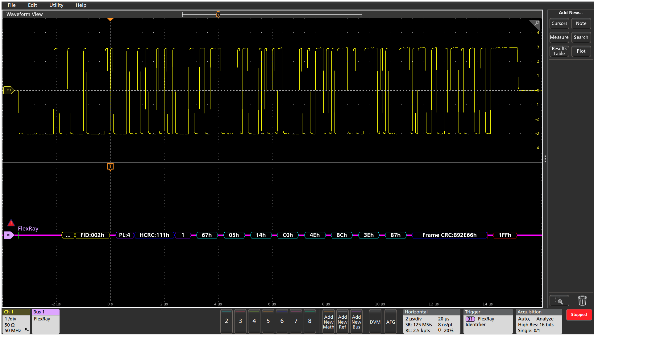
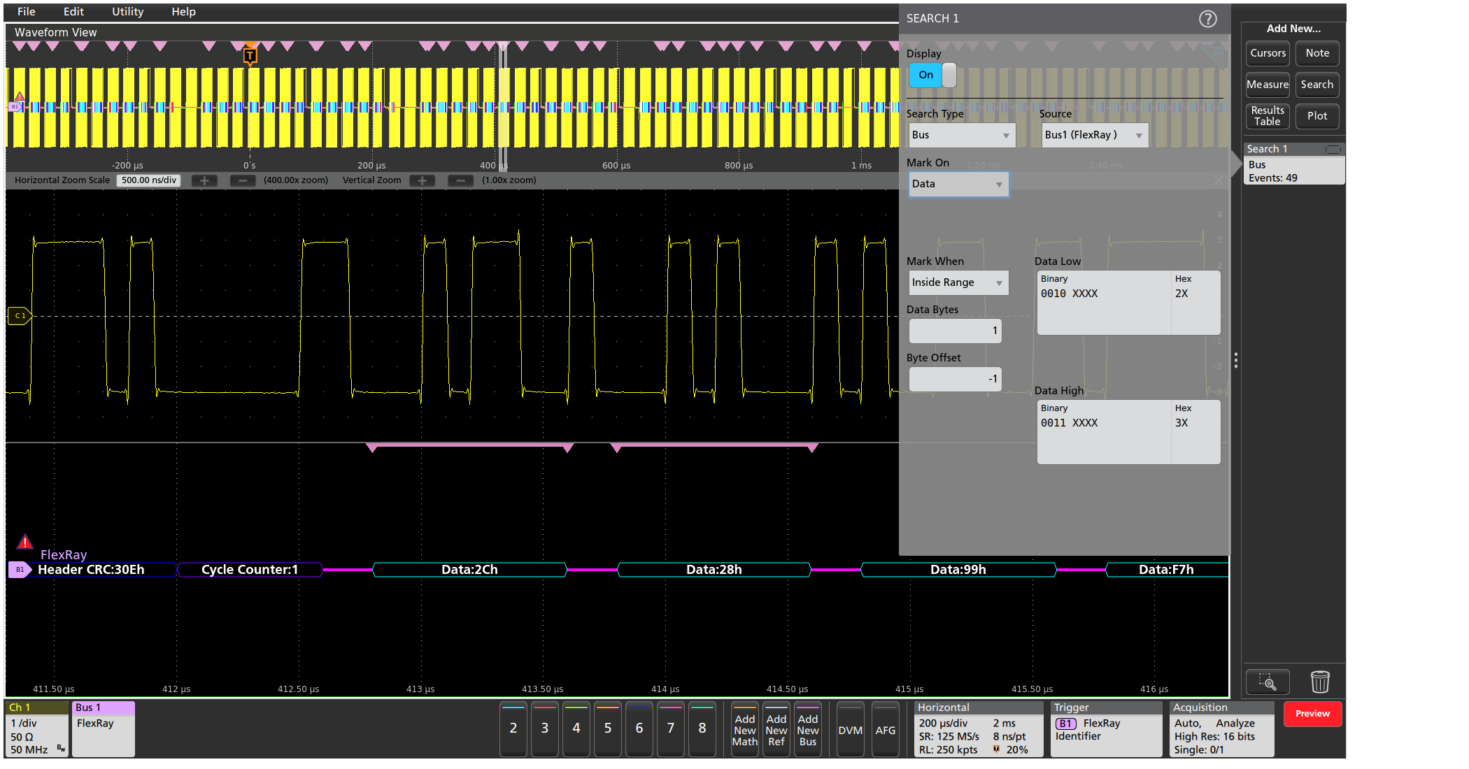
SENT Characteristics1
| Characteristic | Description |
|---|---|
| SENT source | Analog channels Digital channels Active Math channels Active Reference channels |
| Thresholds | Per-channel thresholds |
| Recommended Probing | Single-ended |
| Polarity | Normal Inverted |
| Clock Tick | 1 μs - 300 μs |
| Tick Tolerance | 1% - 30% |
| Fast Data Channels | 1 or 2 |
| Data Nibbles (1 Fast Data Channel) | 3, 4, or 6 nibbles |
| Channel Widths (C1/C2) (2 Fast Data Channels) | 12/12, 14/10, or 16/8 bits |
| Pause Pulse | Yes No |
| Slow Channel | None Enhanced w/ 4-bit ID Enhanced w/ 8-bit ID Short |
| Formats Available | Mixed Hex Binary Hex Mixed Decimal |
| Characteristic | Description |
|---|---|
| Bus | Bus only |
| Bus and Waveforms | Simultaneous display of bus and digital waveforms |
| Results Table | Decoded packet data in a tabular view |
| Characteristic | Description |
|---|---|
| Trigger On | Start of Packet Fast Channel(s) (Status/Communication, Data) Slow Channel (Message ID, Data) CRC Error (Fast channel, Slow channel) |
| Characteristic | Description |
|---|---|
| Search On | Start of Packet Fast Channel(s) (Status/Communication, Data) Slow Channel (Message ID, Data) Pause Pulse (Number of Ticks) Error (Frame Length, Fast channel CRC, Slow channel CRC) |
| Characteristic | Description |
|---|---|
| Maximum Clock/Data Rate | Up to 10 Mb/s (for automated decoding of bus) |
| Decode Display | Sync (green packet) Fast Channel Status (purple packet) Slow Channel Message ID (yellow packet) Data (cyan packet) CRC (purple packet) Pause (purple packet) Errors (red packet) |
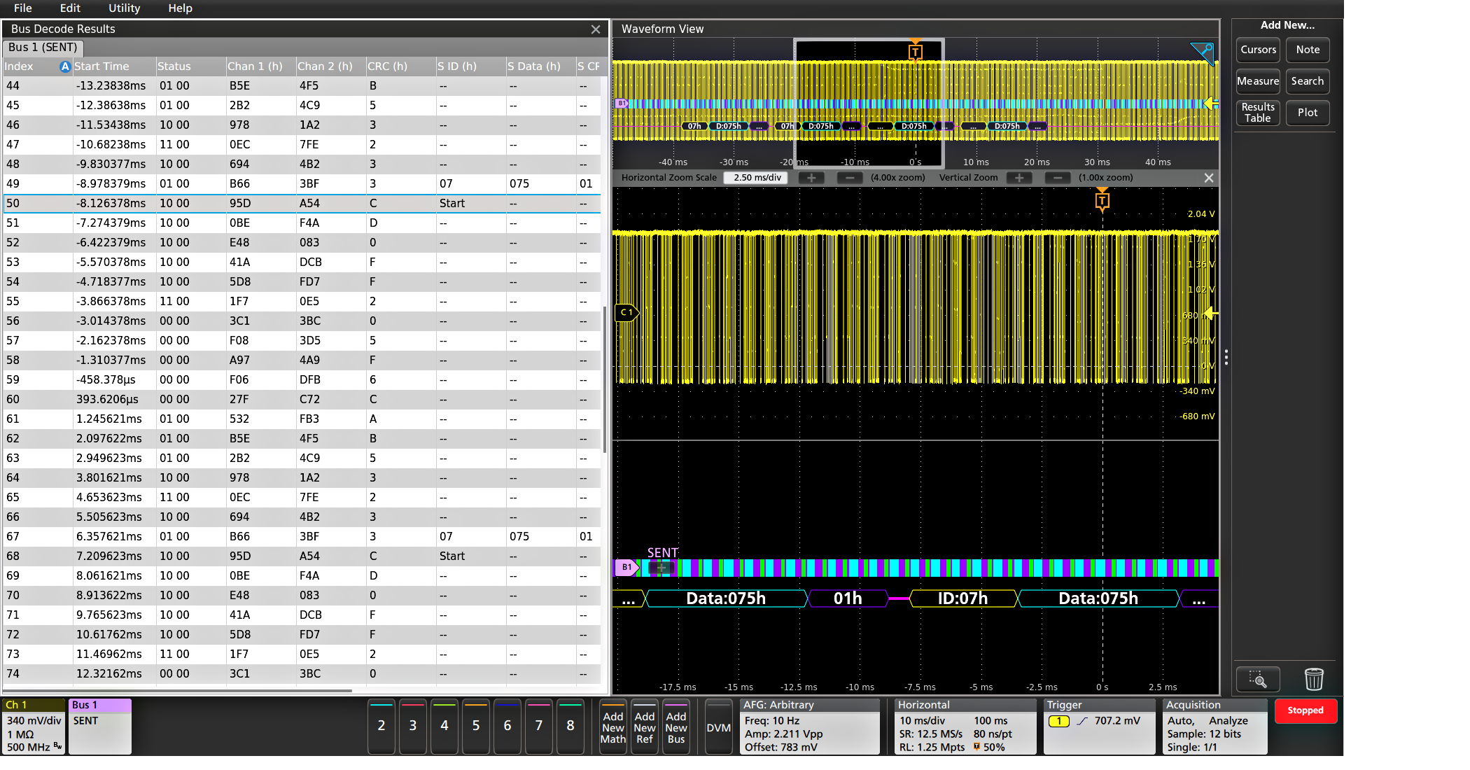
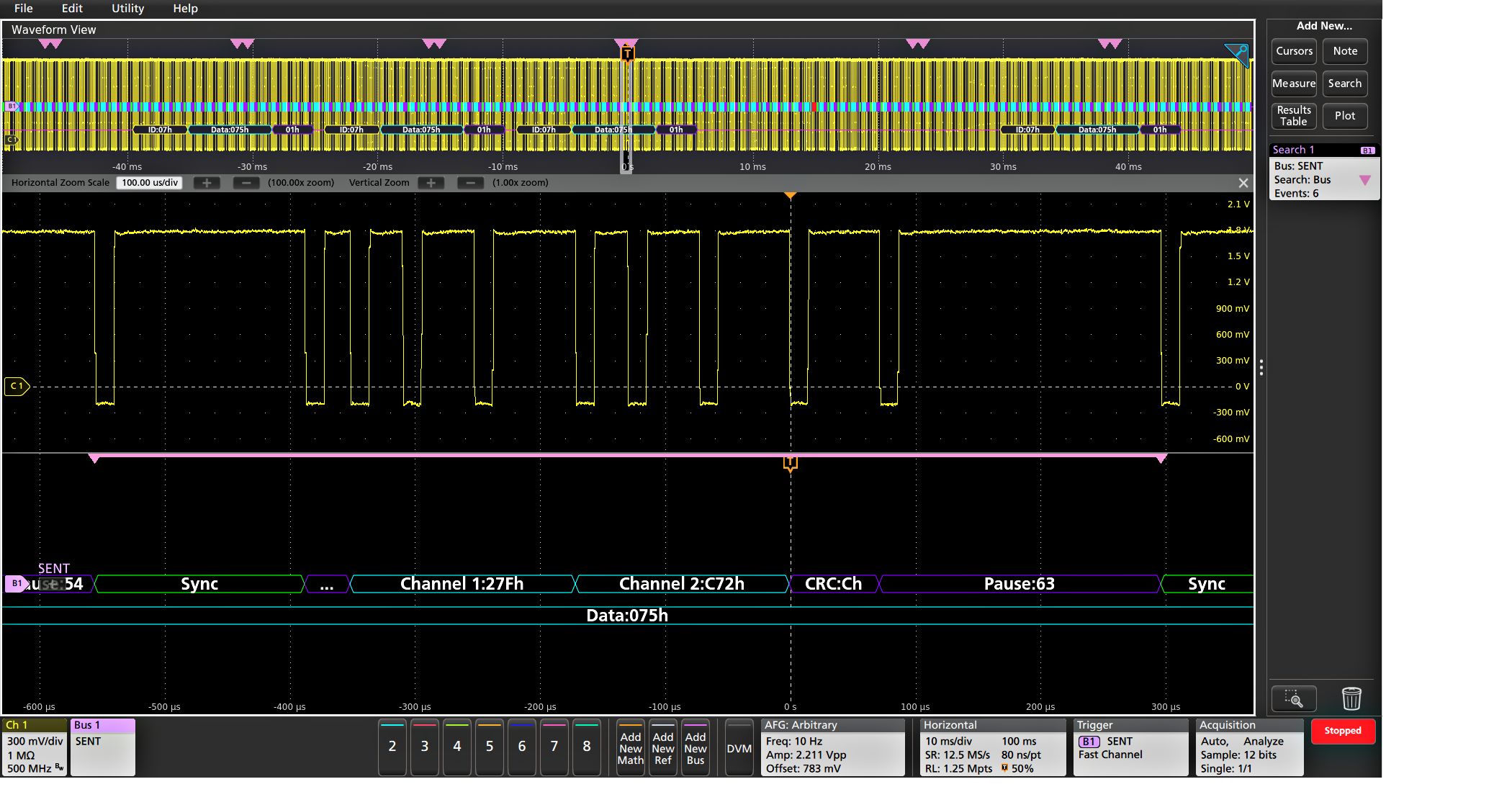
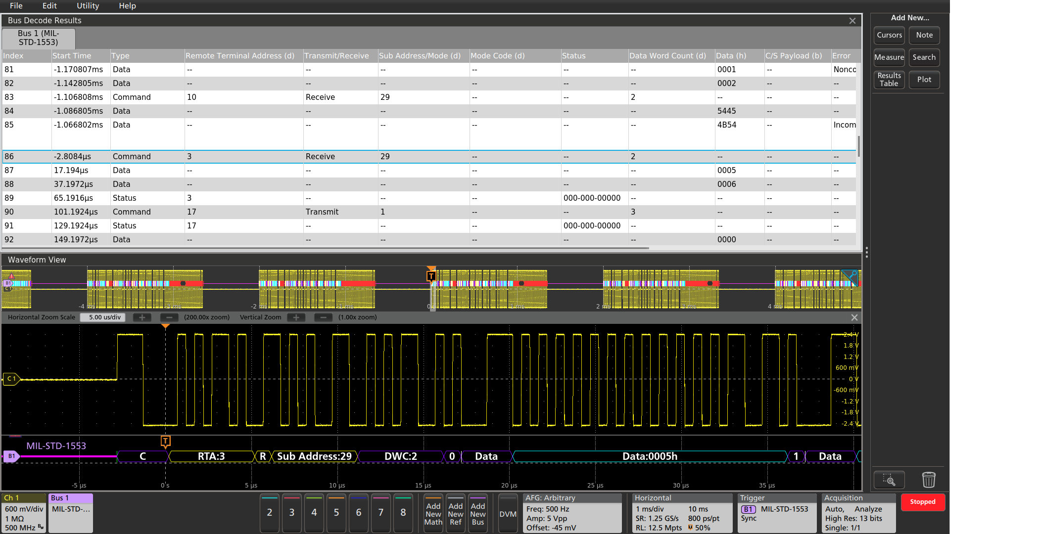
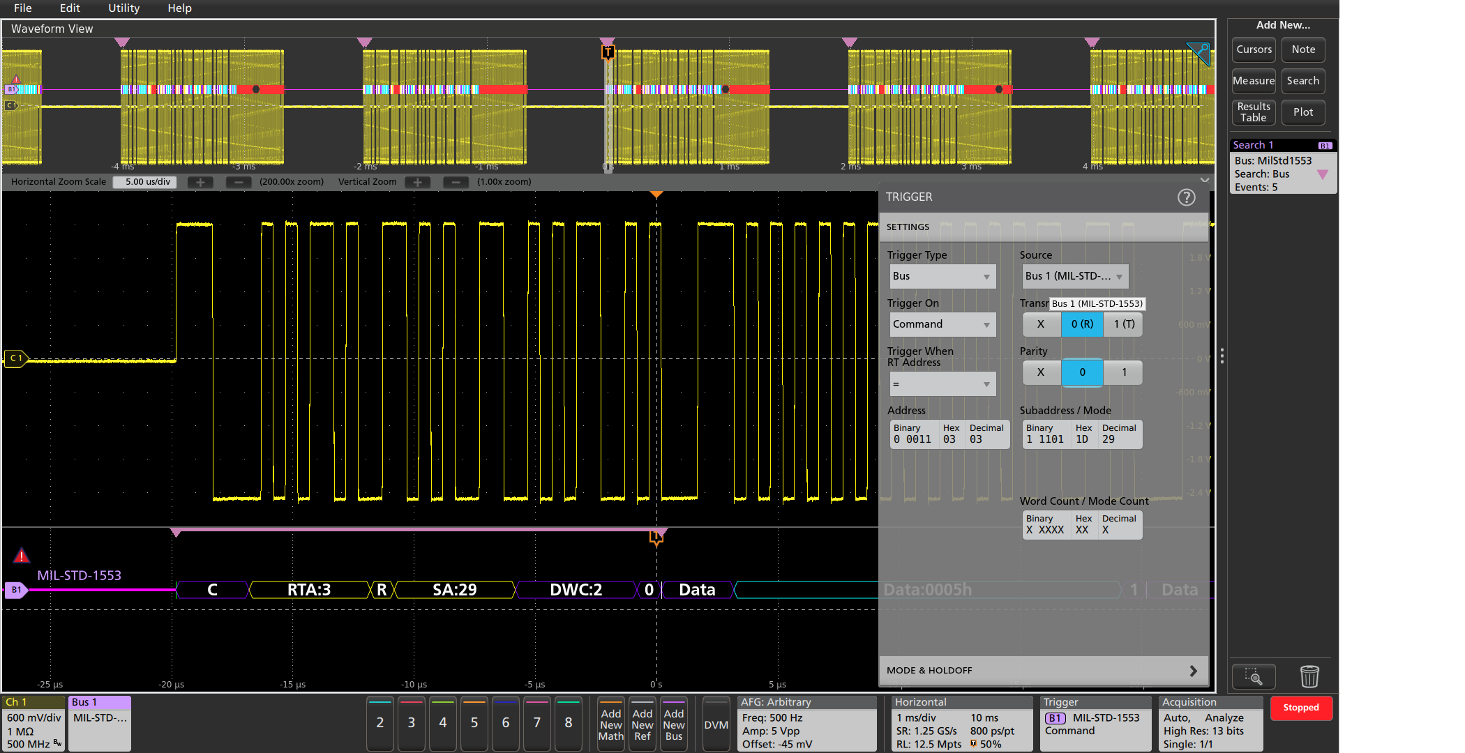
MIL-STD-1553 characteristics
| Characteristic | Description |
|---|---|
| MIL-STD-1553 Source | Analog channels Active Math channels Active Reference channels |
| Polarity | Normal Inverted |
| Thresholds | Single-ended: Per-channel thresholds Differential: High and low thresholds |
| Recommended Probing | Single-ended or differential |
| Bit Rate | 1 Mb/s per the standard |
| Response Time | 2 µs-100 µs |
| Formats Available | Mixed Hex Mixed ASCII Hex Binary |
| Characteristic | Description |
|---|---|
| Bus | Bus only |
| Results Table | Decoded packet data in a tabular view |
| Characteristic | Description |
|---|---|
| Trigger and/or Search On | Sync Command (Transmit/Receive Bit, Parity, Subaddress / Mode, Word Count / Mode Count, and RT Address =, ≠, <, ≤, >, ≥, Inside Range, Outside Range) Status (Parity, Bit 9 - Message Error, Bit 10 - Instrumentation, Bit 11 - Service Request, Bit 15 - Broadcast Command Received, Bit 16 - Busy, Bit 17 - Subsystem Flag, Bit 18 - Dynamic Bus Control Acceptance, Bit 19 - Terminal Flag, and Data =, ≠, <, ≤, >, ≥, Inside Range, Outside Range) Data (Parity, and Data =, ≠, <, ≤, >, ≥, Inside Range, Outside Range) Time (RT / IMG) (> Maximum, < Minimum, Inside range, Outside Range) Error (Parity Error, Sync Error, Manchester Error (trigger only), Non-contiguous Data) |
| Characteristic | Description |
|---|---|
| Maximum Clock/Data Rate | Up to 1Mb/s (for automated decoding of bus) |
| Decode Display | Start (green bar) Sync (purple packet with Word Type identified) Address (yellow packet) R/T (purple packet) Word Count (purple packet) Data (cyan packet) Parity (purple packet) Errors (red packet) Stop (red bar) |
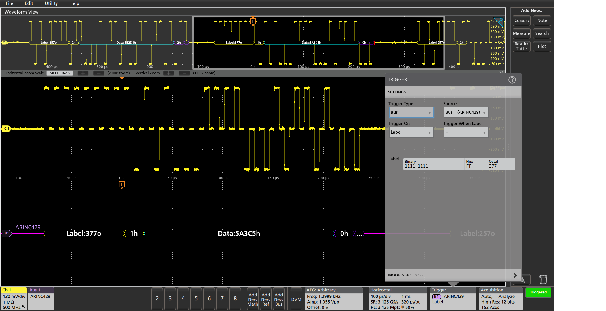
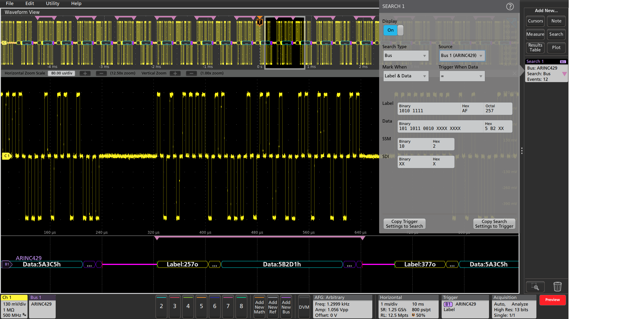
ARINC 429 characteristics (ARINC Specs 429 PART 1-17)
| Characteristic | Description |
|---|---|
| ARINC 429 Source | Analog channels Active Math channels Active Reference channels |
| Signal Type | Differential |
| Polarity | Normal Inverted |
| Thresholds | High and low thresholds |
| Recommended Probing | Differential |
Bit Rate Selection: Predefined list of rates Custom | 12.5 kb/s, 100 kb/s 10 kb/s - 1 Mb/s |
| Data Format | Data (19 bits) SDI+Data (21 bits) SDI+Data+SSM (23 bits) |
| Formats Available | Mixed Hex Hex Binary |
| Characteristic | Description |
|---|---|
| Bus | Bus only |
| Results Table | Decoded packet data in a tabular view |
| Characteristic | Description |
|---|---|
| Trigger and/or Search On | Word Start Label (when =, ≠, <, ≤, >, ≥, Inside Range, Outside Range) Data (when =, ≠, <, ≤, >, ≥, Inside Range, Outside Range) Label and Data (Label value and Data =, ≠, <, ≤, >, ≥, Inside Range, Outside Range) Word End Error (Any Error, Parity Error, Word Error, Gap Error) |
| Characteristic | Description |
|---|---|
| Decode Display | Start (green bracket) Label (yellow box) Source Destination Identifier (yellow box) Data (cyan box) Sign/Status Matrix (purple box) Parity (purple box) Stop (red bracket) Error (red box) |
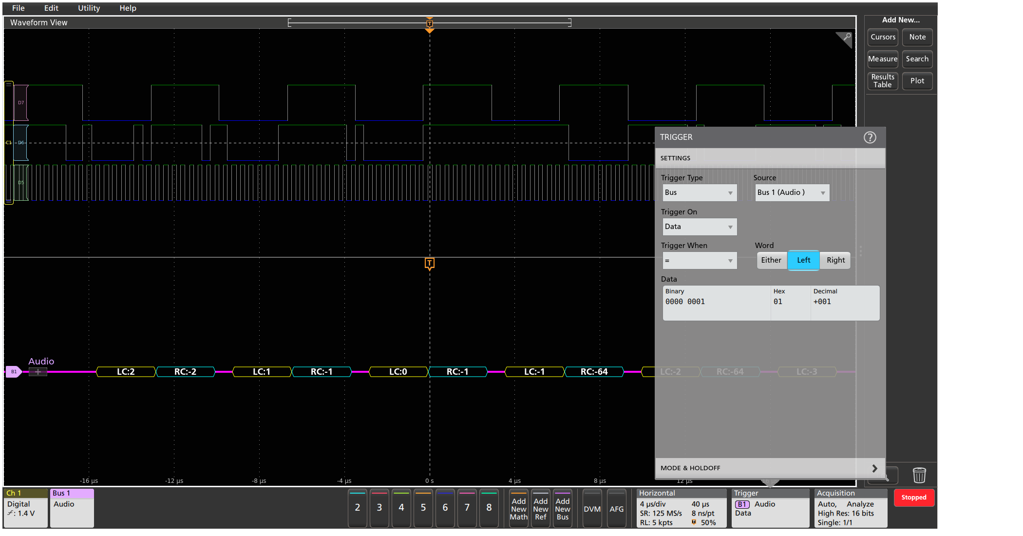
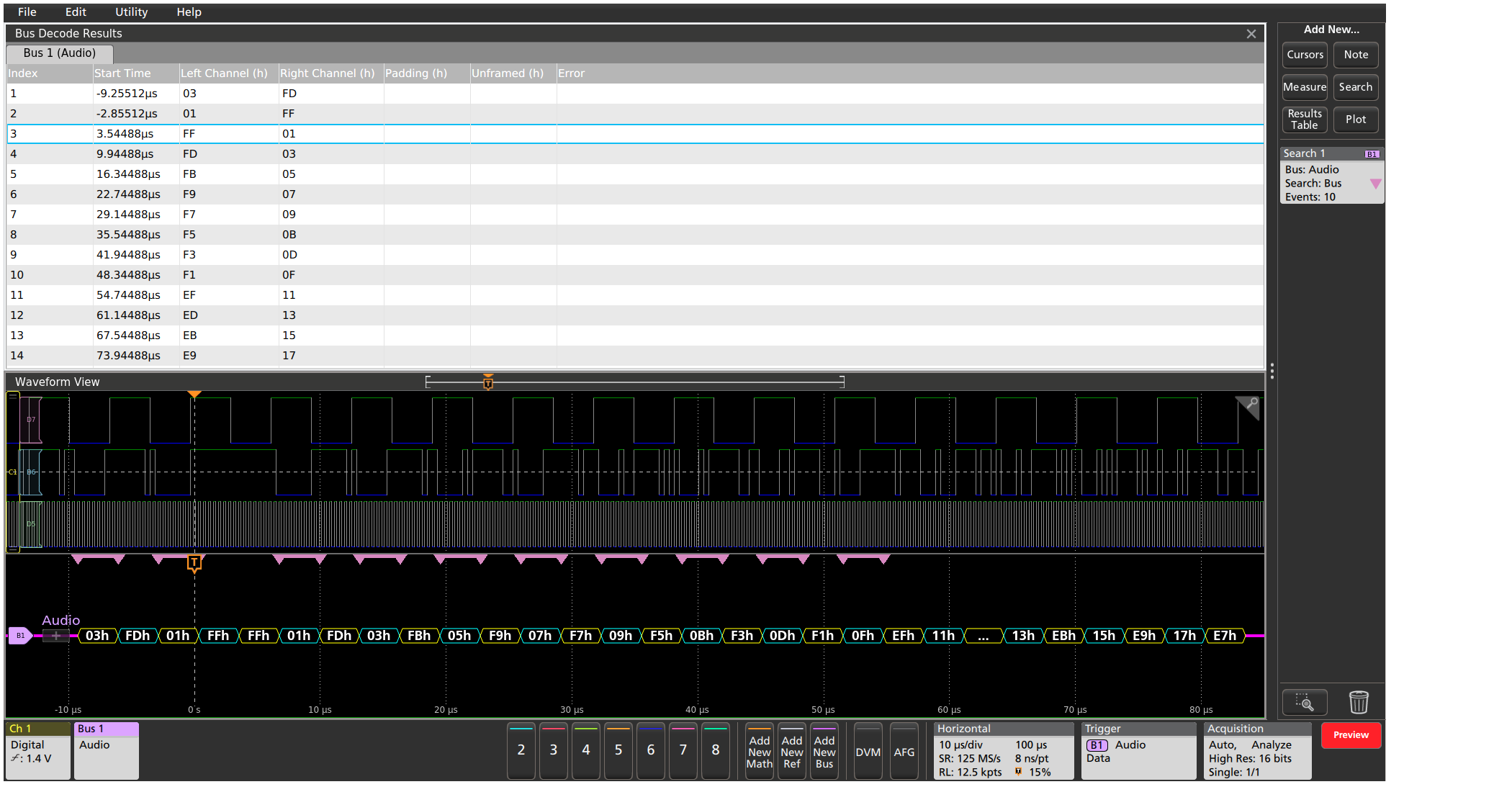
Audio characteristics
| Characteristic | Description |
|---|---|
Audio Sources (Bit Clock, Word Select, Data) | Analog channels Digital channels Active Math channels1 Active Reference channels1 |
Thresholds | Per-channel thresholds |
Bit Clock Polarity | Rising Edge Falling Edge |
Word Select Polarity | Normal Invert |
Data Polarity | Active High Active Low |
Word Size | 4 - 32 bits |
Formats Available | Hex Binary Signed Decimal |
| Characteristic | Description |
|---|---|
Bus | Bus only |
Bus and Waveforms | Simultaneous display of bus and digital waveforms |
Results Table | Decoded packet data in a tabular view |
| Characteristic | Description |
|---|---|
Trigger and/or Search On | Word Select (I2S, LJ, RJ only) Frame Sync (TDM only) Data (when =, ≠, <, >, ≤, ≥, Inside Range, Outside Range; Left, Right, or Either Word) |
| Characteristic | Description |
|---|---|
Maximum Clock/Data Rate | All but 3 Series MDO: Up to 10 Mb/s (for automated decoding of bus) 3 Series MDO: Up to 12.5 Mb/s (for automated decoding of I2S/LJ/RJ bus) 3 Series MDO: Up to 25 Mb/s (for automated decoding of TDM bus) |
Decode Display | Left Channel Data (I2S, LJ, RJ) (yellow box) Right Channel Data (I2S, LJ, RJ) (cyan box) Channel 1 Data (TDM) (yellow box) Channel 2 - N Data (TDM) (cyan box) |
USB 2.0 Characteristics (Version 2.0)
| Characteristic | Description |
|---|---|
| USB 2.0 Source(s) | Analog channels Digital channels (single-ended) Active Math channels Active Reference channels |
| Thresholds | Per-channel thresholds |
| Speed | USB 1.0 (1.5 Mbps) USB 1.1 (12 Mbps) USB 2.0 (480 Mbps) |
| Recommended Probing: | |
| USB 1.0 and USB 1.1 USB 2.0 | Single-ended Differential |
| Formats Available for USB 1.0, USB 1.1, and USB 2.0 | Mixed Hex Hex Binary Mixed ASCII |
| Characteristic | Description |
|---|---|
| Bus | Bus only |
| Bus and Waveforms | Simultaneous display of bus and digital waveforms |
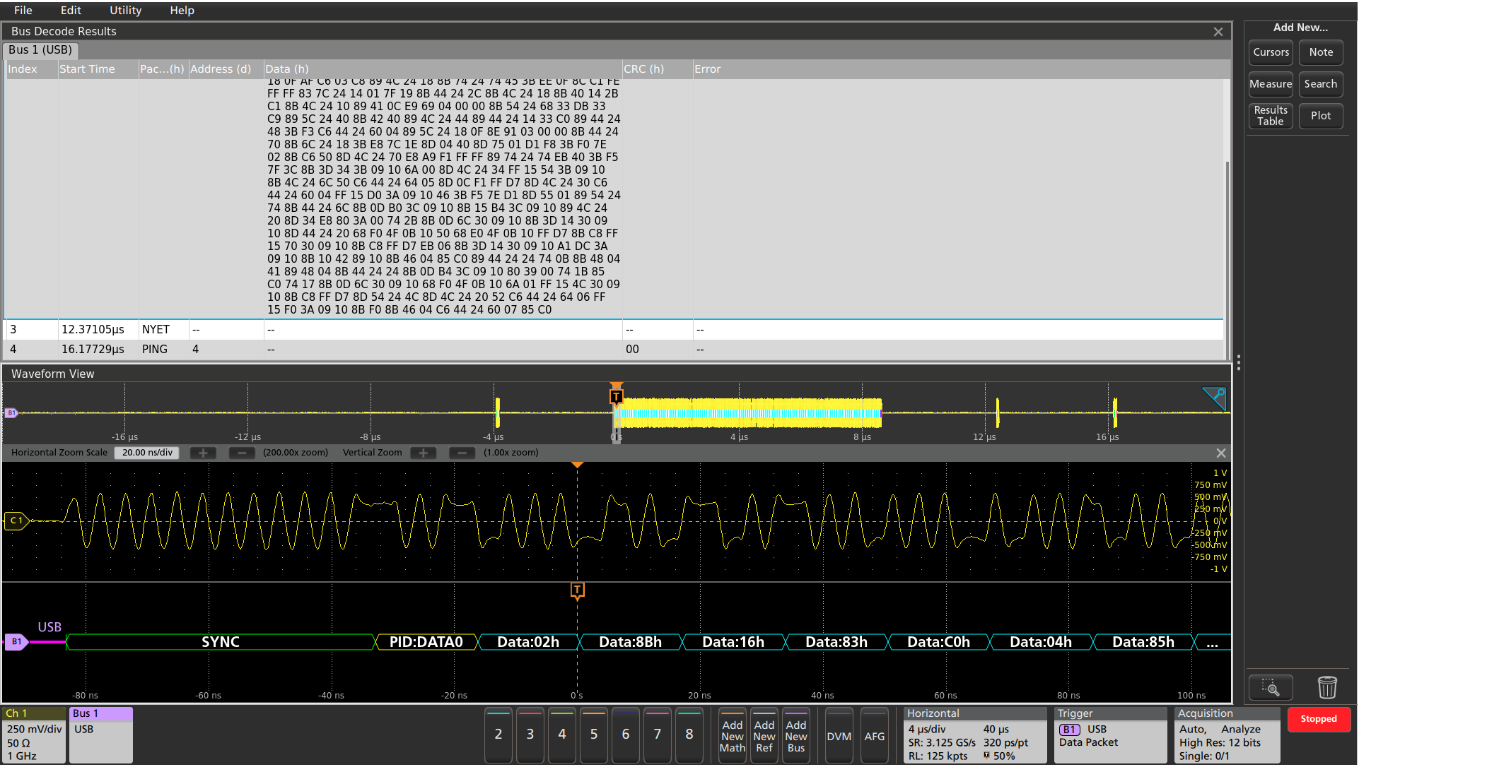
| Results Table | Decoded packet data in a tabular view |
| Characteristic | Description |
|---|---|
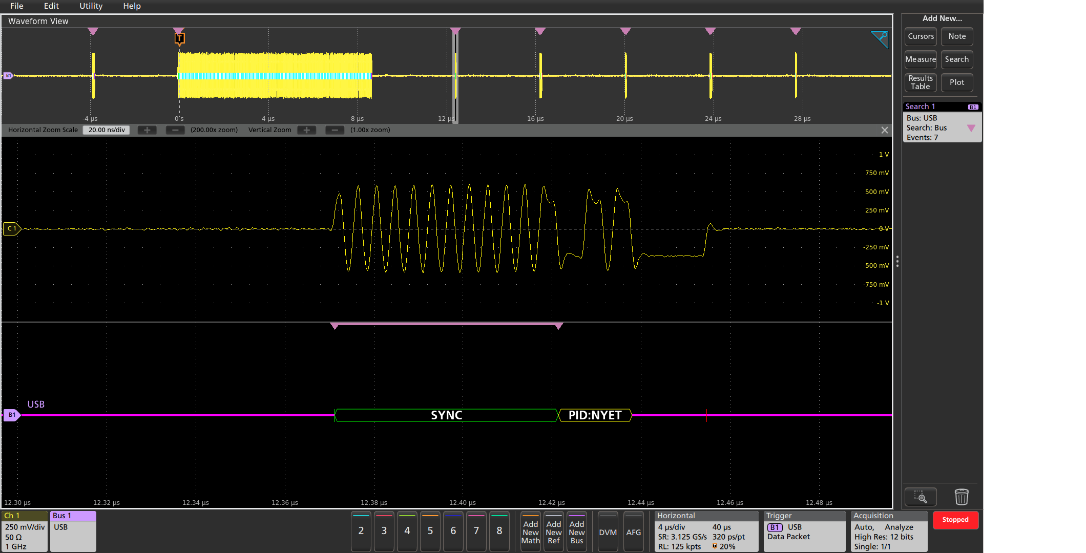
| Trigger On | Sync Reset Suspend Resume End of Packet Token (address) Packet Data Packet Handshake Packet: ACK, NAK, STALL, NYET (USB 2.0 only) Special Packet: PRE (USB 1.1 only), ERR, SPLIT, PING, Reserved Error: PID check, CRC5 or CRC16, Bit stuffing (USB 1.0 and USB 1.1 only) |
| Characteristic | Description |
|---|---|
| Search On | Sync Reset Suspend Resume End of Packet Token (address) Packet Data Packet Handshake Packet: ACK, NAK, STALL, NYET (USB 2.0 only) Special Packet: PRE (USB 1.1 only), ERR, SPLIT, PING, Reserved Error: PID check, CRC5 or CRC16, Bit stuffing (USB 1.0 and USB 1.1 only) |
| Characteristic | Description |
|---|---|
| Decode Display | Start of packet (green bar) Sync (green packet) PID (yellow packet) Token (address) (yellow packet) Data (cyan packet) CRC (purple packet) Error (red packet) End of packet (red bar) |
USB Characteristics (Version 3.0, 3.1 Gen 1, 3.2 Gen 1)
| Characteristic | Description |
|---|---|
| USB Source(s) | Analog channels Digital channels Active Math channels Active Reference channels |
| Thresholds | Per-channel thresholds |
| Speed | USB 1.0 (1.5 Mbps) USB 1.1 (12 Mbps) USB 2.0 (480 Mbps) USB 3.0 (5 Gbps) USB 3.1 Gen 1 (5 Gbps) USB 3.2 Gen 1 (5 Gbps) |
| Recommended Probing: | |
| USB 1.0, USB 1.1, USB 3.0, USB 3.1 Gen 1, and USB 3.2 Gen 1 | Single-ended |
| USB 2.0, USB 3.0, USB 3.1 Gen 1, and USB 3.2 Gen 1 | Differential |
| Formats Available: | |
| USB 1.0, USB 1.1, and USB 2.0 | Hex Binary Mixed Hex Mixed ASCII |
| USB 3.0, USB 3.1 Gen 1, and USB 3.2 Gen 1 | Hex Binary Mixed Hex |
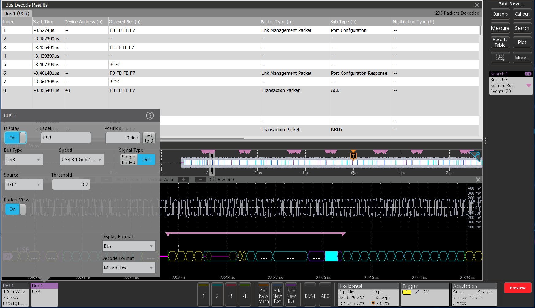
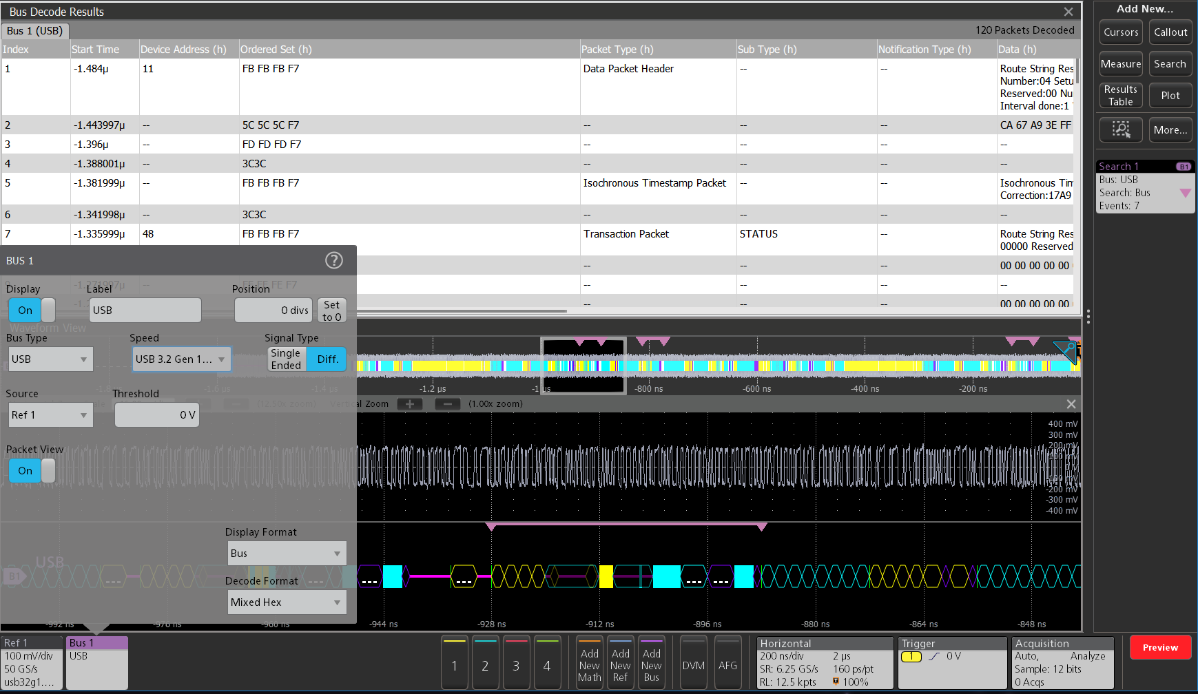
| Packet View for USB 3.0, USB 3.1 Gen 1, and USB 3.2 Gen 1 | On Off |
| Characteristic | Description |
|---|---|
| Bus | Bus only |
| Results Table | Decoded packet data in a tabular view |
| Characteristic | Description |
|---|---|
| Search On | Packet View On Only
Packet View Off Only
Control Character: COM, EDB, END, EPF, SDP, SHP, SKP, SLC, SUB, Any |
Ethernet characteristics1
| Characteristic | Description |
|---|---|
Ethernet Source(s) | Analog channels Active Math channels Active Reference channels |
Thresholds | Per-channel thresholds |
Speed | 10BASE-T 100BASE-TX |
Recommended Probing | Differential |
Formats Available | Mixed Hex Hex Binary Mixed ASCII |
| Characteristic | Description |
|---|---|
Bus | Bus only |
Bus and Waveforms | Simultaneous display of bus and digital waveforms |
Results Table | Decoded packet data in a tabular view |
| Characteristic | Description |
|---|---|
Trigger On | Start Frame Delimiter MAC Addresses Q-Tag Control Information MAC Length/Type IPv4 Header TCP Header MAC Data TCP-IPv4 Client Data Idle End of Packet Frame Check Sequence (CRC) Error |
| Characteristic | Description |
|---|---|
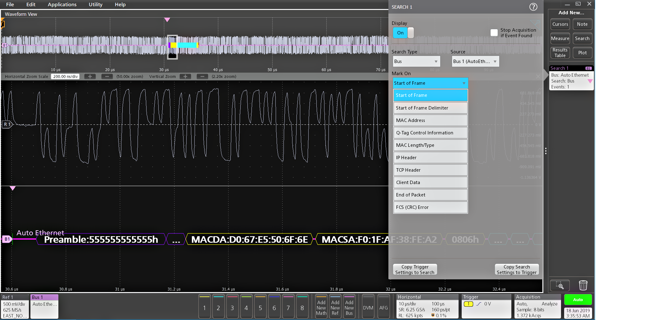
Search On | Start Frame Delimiter MAC Addresses Q-Tag Control Information MAC Length/Type IPv4 Header TCP Header MAC Data TCP-IPv4 Client Data Idle End of Packet Frame Check Sequence (CRC) Error |
| Characteristic | Description |
|---|---|
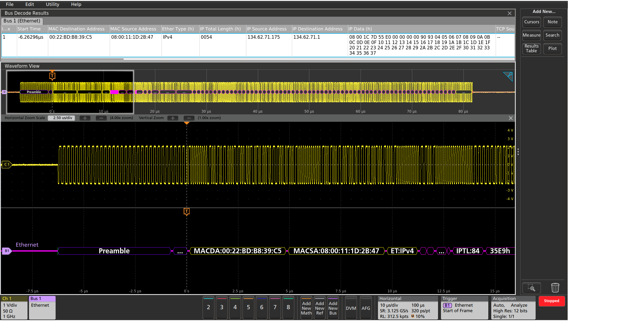
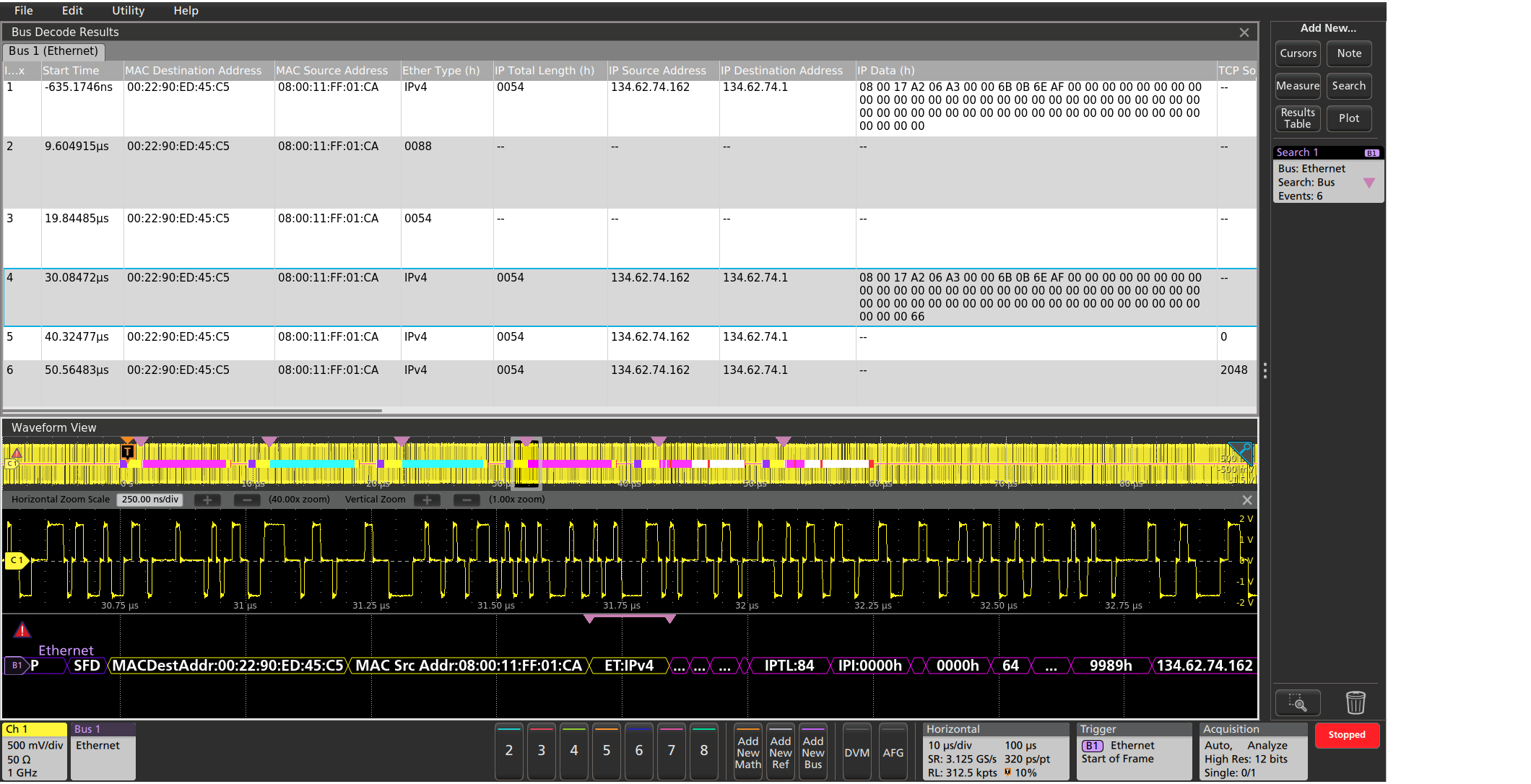
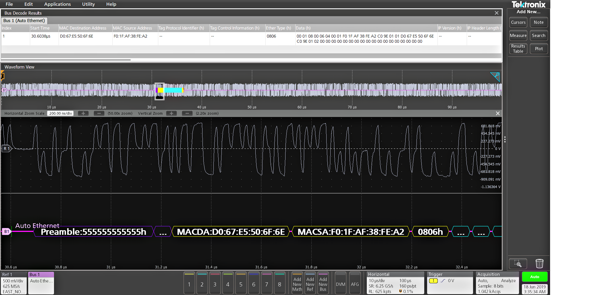
Decode Display | Start of Packet (green bar) Preamble (purple packet) SFD (purple packet) Address (yellow packet) EtherType (yellow packet) IP packet (purple packet) Data (cyan packet) IPv4 packet (pink packet) TCP packet (white packet) Frame Check Sequence (yellow packet) Error (red packet) End of packet (red bar) |
SPMI characteristics1 (Version 2.0)
| Characteristic | Description |
|---|---|
SPMI Sources (Clock and Data) | Analog channels Digital channels Active Math channels Active Reference channels |
Thresholds | Per-channel thresholds |
Recommended Probing | Single-ended |
Formats Available | Mixed Hex Hex Binary |
| Characteristic | Description |
|---|---|
Bus | Bus only |
Bus and Waveforms | Simultaneous display of bus and digital waveforms |
Results Table | Decoded packet data in a tabular view |
| Characteristic | Description |
|---|---|
Trigger On | Sequence Start Condition (SSC) Reset Sleep Shutdown Wakeup Authenticate Master Read Master Write Register Read Register Write Extended Register Read Extended Register Write Extended Register Read Long Extended Register Write Long Device Descriptor Block Master Read Device Descriptor Block Slave Read Register 0 Write Transfer Bus Ownership Parity Error |
| Characteristic | Description |
|---|---|
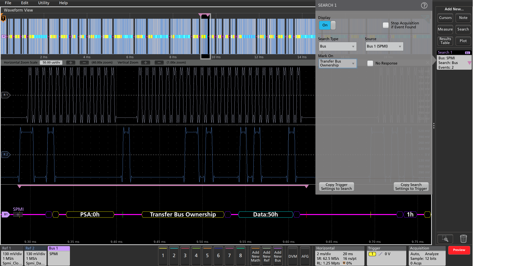
Search On | Sequence Start Condition (SSC) Reset Sleep Shutdown Wakeup Authenticate Master Read Master Write Register Read Register Write Extended Register Read Extended Register Write Extended Register Read Long Extended Register Write Long Device Descriptor Block Master Read Device Descriptor Block Slave Read Register 0 Write Transfer Bus Ownership Parity Error |
| Characteristic | Description |
|---|---|
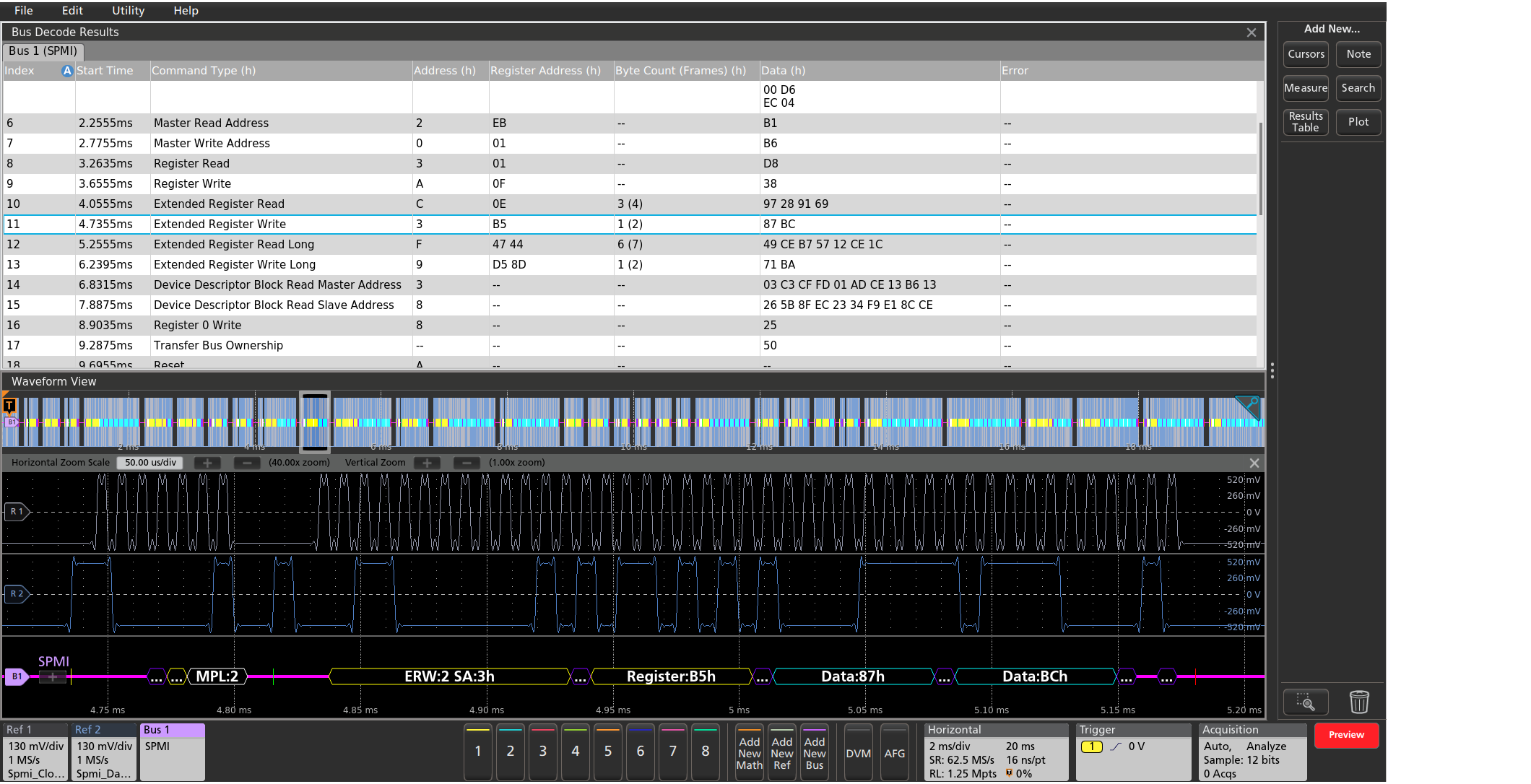
Decode Display | Arbitration Start (yellow bar) Connect Bit (purple packet) Master ID (purple packet) Alert Bit (yellow packet) Slave Request Bit (yellow packet) Master Priority Level (gray packet) SSC (green bar) Command Frame, including Byte Count 2 (yellow packet) Address (yellow packet) Data (cyan packet) Parity (purple packet) Ack/Nack (purple packet) Parity error (red packet) End of packet (red bar) |
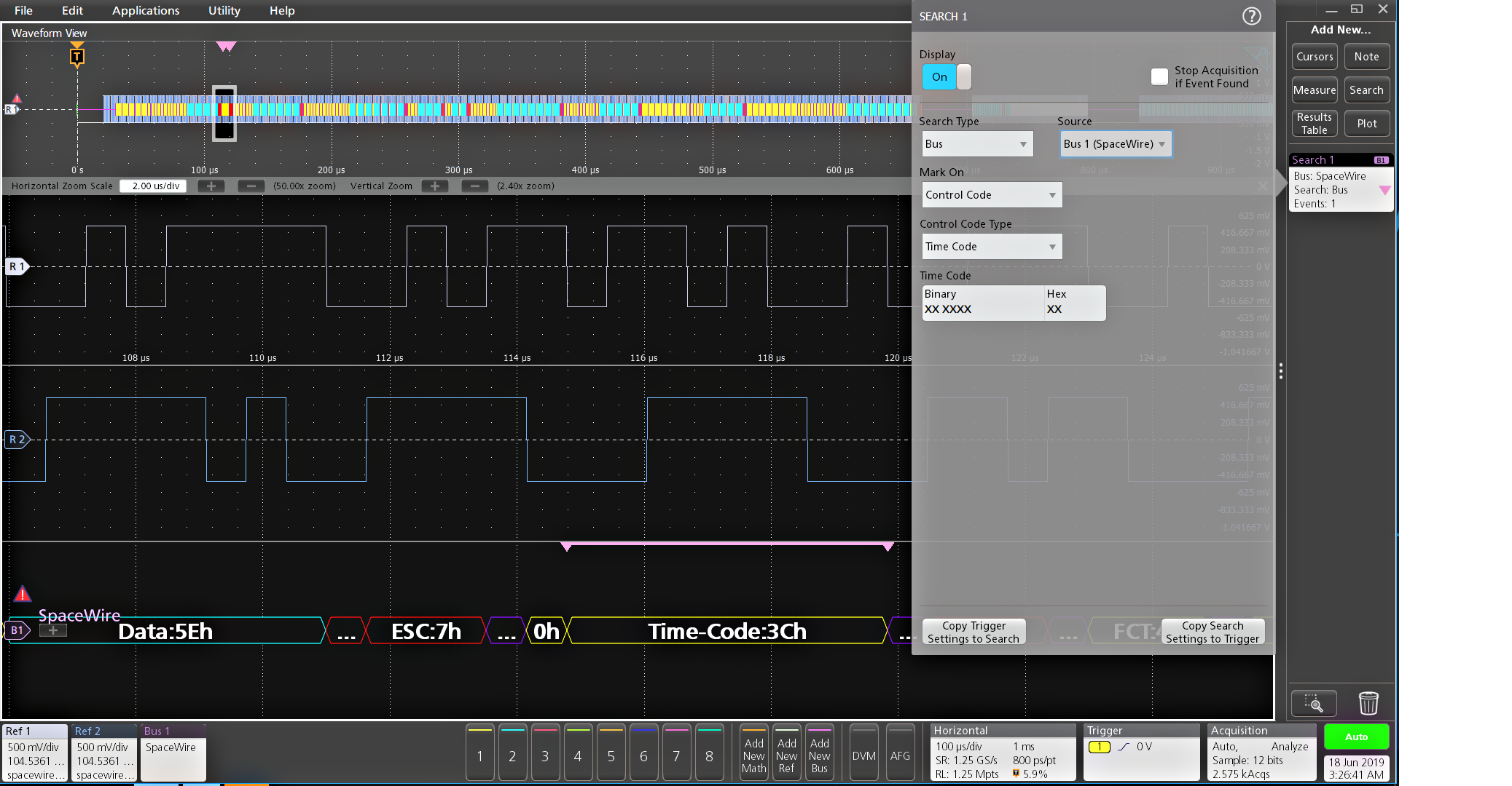
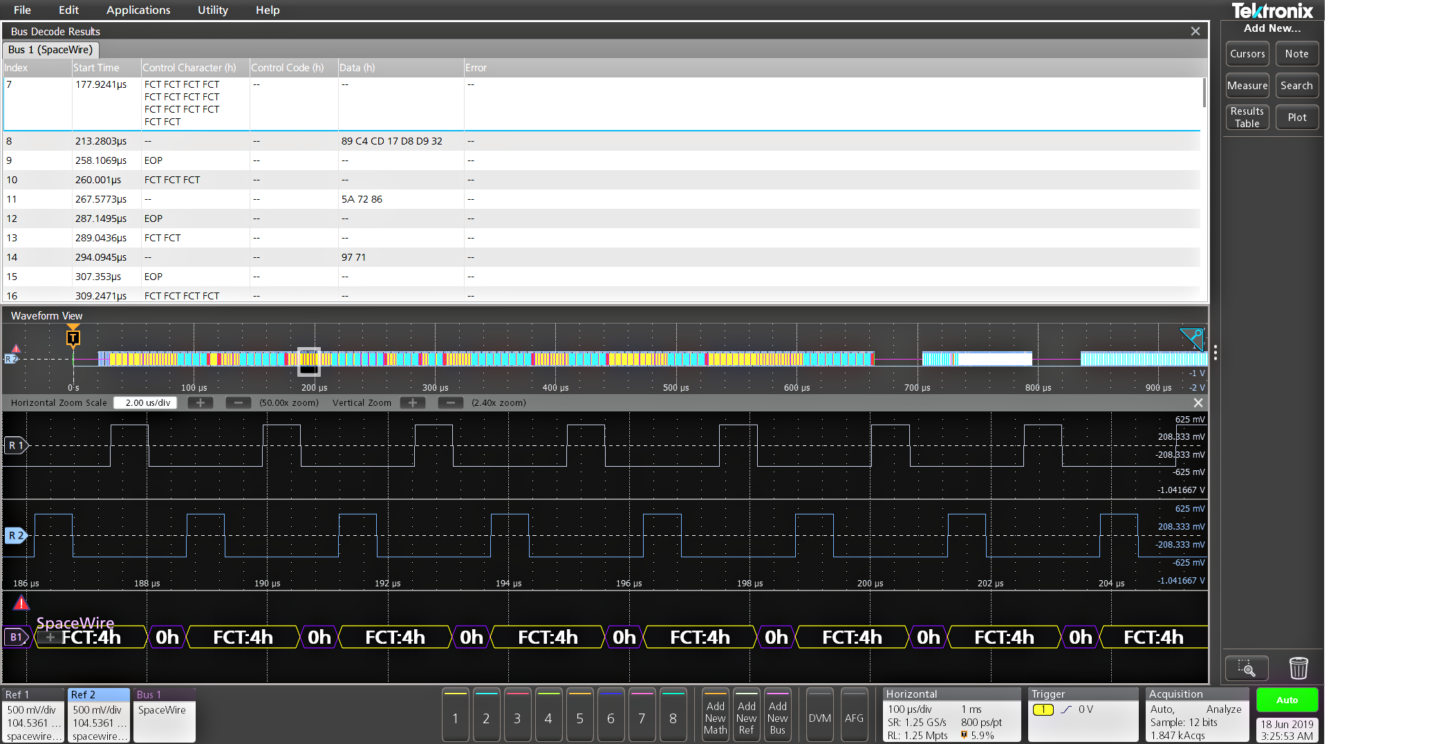
SpaceWire characteristics
| Characteristic | Description |
|---|---|
SpaceWire Sources (Strobe and Data) | Analog Channels Digital Channels Active Math Channels Active Reference Channels |
Thresholds | Per-Channel Thresholds |
Recommended Probing | Differential |
Address/Data Formats Available | Hex Binary |
| Characteristic | Description |
|---|---|
Bus | Bus Only |
Bus and Waveforms | Simultaneous display of bus and digital waveforms |
Results Table | Decoded packet data in a tabular view |
| Characteristic | Description |
|---|---|
Search On | Synchronization Control Code Control Character Data Errors |
| Characteristic | Description |
|---|---|
Maximum Clock/Data Rate | 2 Mbits/sec to 200 Mbits/sec |
Decode Display | Null Control Character Control Code FCT Time-Code Parity Data-Control Flag Data End Of Packet Error End Of Packet Escape Sequence Escape Error Start FCT Start NULL |
Automotive Ethernet (10BASE-T1S) characteristics
| Characteristic | Description |
|---|---|
| 10Base-T1S Sources | Analog channels Digital channels Active Math channels Active Reference channels |
| Thresholds | Per-channel Thresholds |
| Probing | Single-ended Differential |
| Bit Rate | Upto 1Gbps |
| Packet View | On Off |
| Formats Available | Hex Binary Mixed Hex |
| Characteristic | Description |
|---|---|
| Bus | Bus only |
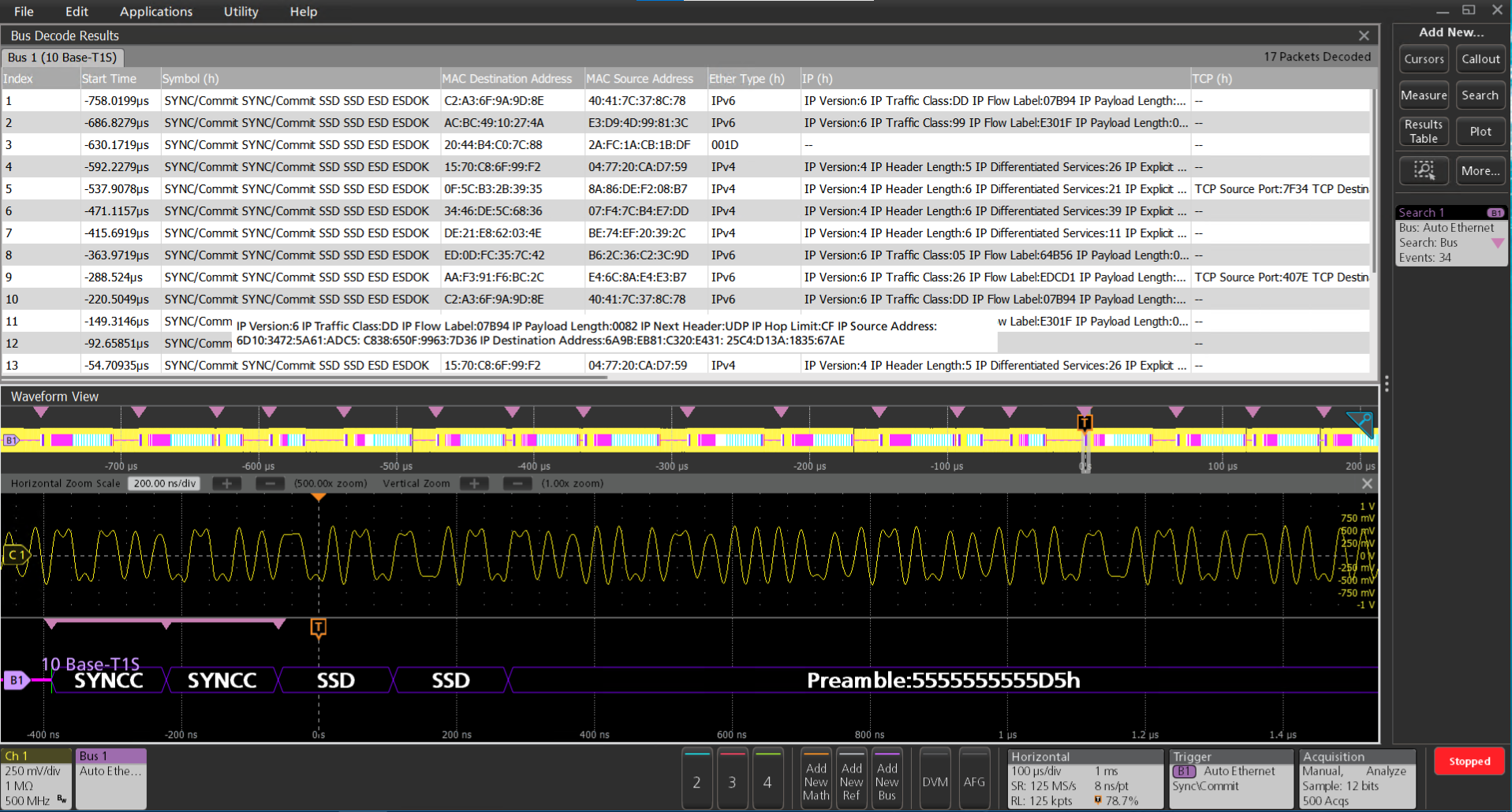
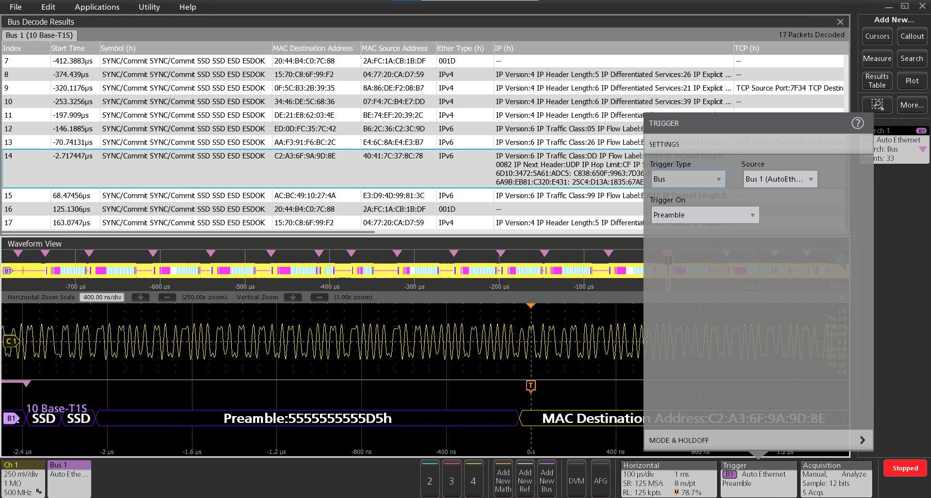
| Results Table | Decoded packet data in a tabular view |
| Characteristic | Description |
|---|---|
| Search On | SYNC/Commit Start of Stream Delimiter MAC address: Mac Address Source, Mac Address destination Beacon Ether Type: IPv4 and IPv6 with Header Type: TCP, UDP, ICMP Payload: Payload Bytes, Payload value Data: Data Bytes, Data End of stream Delimiter. End of stream Delimiter Ok Errors: CRC, ESDERR, ESDJAB, Checksum, Any |
| Characteristic | Description |
|---|---|
| Trigger On | SYNC/Commit Start of Stream Delimiter Preamble Beacon End of stream Delimiter. End of stream Delimiter Ok Errors: ESDERR, ESDJAB |
Automotive Ethernet (100BASE-T1) characteristics (Version BRR V3.2)
| Characteristic | Description |
|---|---|
Ethernet Source(s) | Analog Channels Active Math Channels Active Reference Channels |
Thresholds | Per-channel Thresholds |
Speed | 100 Mbits/sec |
Recommended Probing | Differential |
Formats Available | Mixed Hex Hex Binary Mixed ASCII |
| Characteristic | Description |
|---|---|
Bus | Bus Only |
Results Table | Decoded packet data in a tabular view |
| Characteristic | Description |
|---|---|
Search On | Start of Frame Start of Frame Delimiter MAC Addresses Q-Tag Control Information MAC Length/Type IPv4 Header TCP Header MAC Data TCP-IPv4 Client Data End of Packet Frame Check Sequence (CRC) Error |
| Characteristic | Description |
|---|---|
Maximum Clock/Data Rate | 100 Mbits/sec |
Decode Display | Start of Packet (green bar) Preamble (purple packet) SFD (purple packet) Address (yellow packet) EtherType (yellow packet) IP packet (purple packet) Data (cyan packet) IPv4 packet (pink packet) TCP packet (white packet) Frame Check Sequence (yellow packet) Error (red packet) End of packet (red bar) |
8b10b Characteristics (Line encoding)
| Characteristic | Description |
|---|---|
8b10b Sources (Strobe and Data) | Analog Channels Digital Channels Active Math Channels Active Reference Channels |
Thresholds | Per-Channel Thresholds |
Recommended Probing | Differential |
Formats Available | Hex Binary Symbolic |
| Characteristic | Description |
|---|---|
Bus | Bus Only |
Bus and Waveforms | Simultaneous display of bus and digital waveforms |
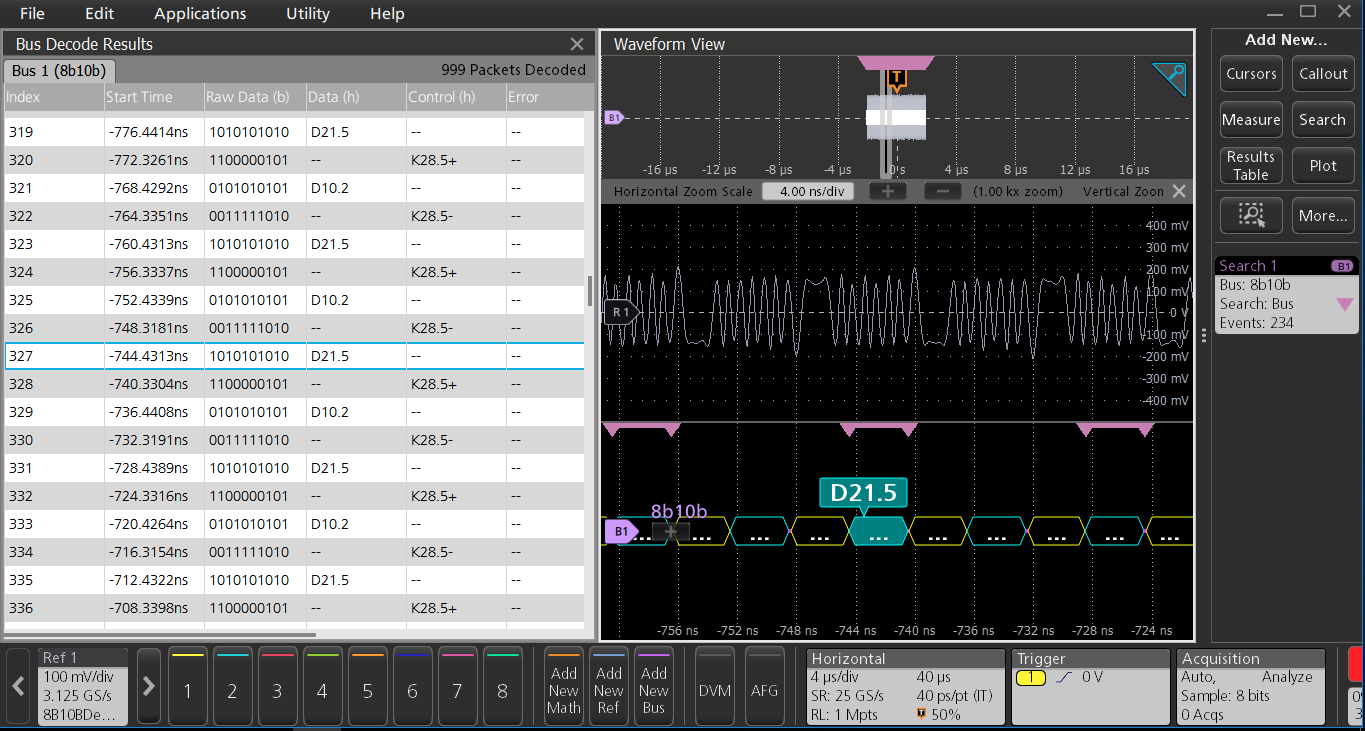
Results Table | Decoded packet data in a tabular view |
| Characteristic | Description |
|---|---|
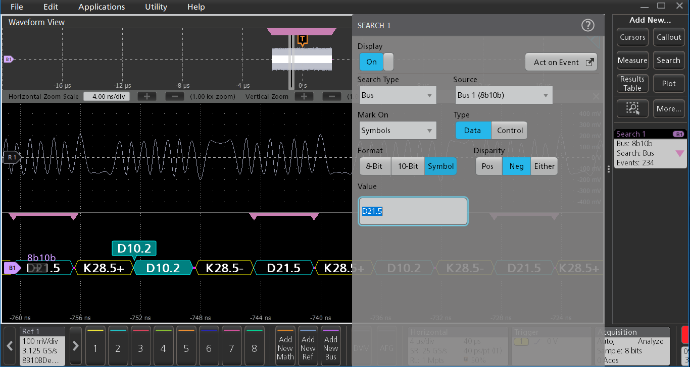
Search On | Symbols [Format:8bit,10bit&symbol] Errors |
| Characteristic | Description |
|---|---|
Maximum Clock/Data Rate | 1 Tbits/sec |
Decode Display | Control Symbol (yellow packet) Data Symbol (cyan packet) |
Error Handling | Invalid Symbols Running Disparity (6 bit and 4 bit) |
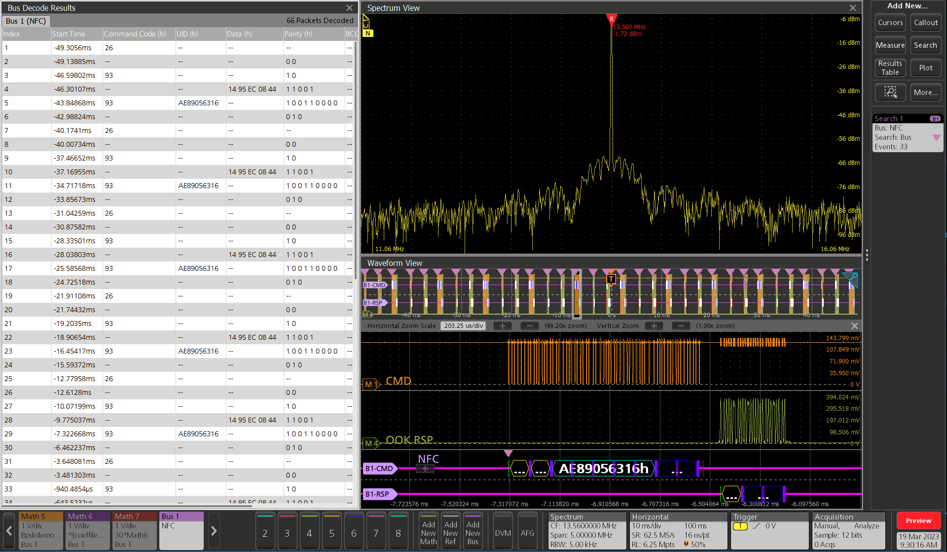
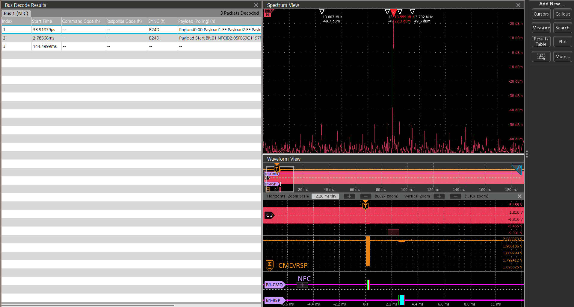
NFC characteristics
| Characteristic | Description |
|---|---|
| NFC sources |
|
| Salient features |
|
| Product differentiators |
|
| Recommended probing |
|
| Bus setup |     |
| Formats available |
|
| Characteristic | Description |
|---|---|
| Bus | Bus only |
| Result Table | Decoded packet data in a tabular view with columns containing:
|

Bus decode
| Characteristic | Description |
|---|---|
| Maximum Data Rate | Max data rate for NFC Type B command is 1.7 Mbps |
| Result table |
|
|
Bus Search
| Characteristic | Description |
|---|---|
| Search ON |
|


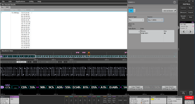
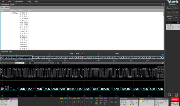
NRZ Characteristics (Line encoding)
| Characteristic | Description |
|---|---|
NRZ Source(s) | Analog Channels Digital Channels Active Math Channels Active Reference Channels |
Thresholds | Per-channel Thresholds |
Recommended Probing | Differential |
Bit Order | MSB First LSB First |
Polarity | Normal Invert |
Formats Available | Hex Binary |
| Characteristic | Description |
|---|---|
Bus | Bus Only |
Bus and Waveforms | Simultaneous display of bus and digital waveforms. |
Results Table | Decoded packet data in a tabular view |
| Characteristic | Description |
|---|---|
Search On | Data Bytes [Maximum 5] |
| Characteristic | Description |
|---|---|
Maximum Clock/Data Rate | 1Gbits/sec |
Decode Display | Data (cyan packet) |
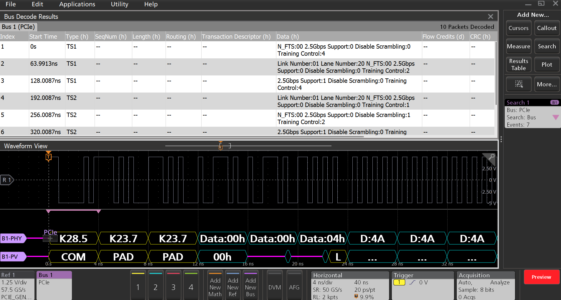
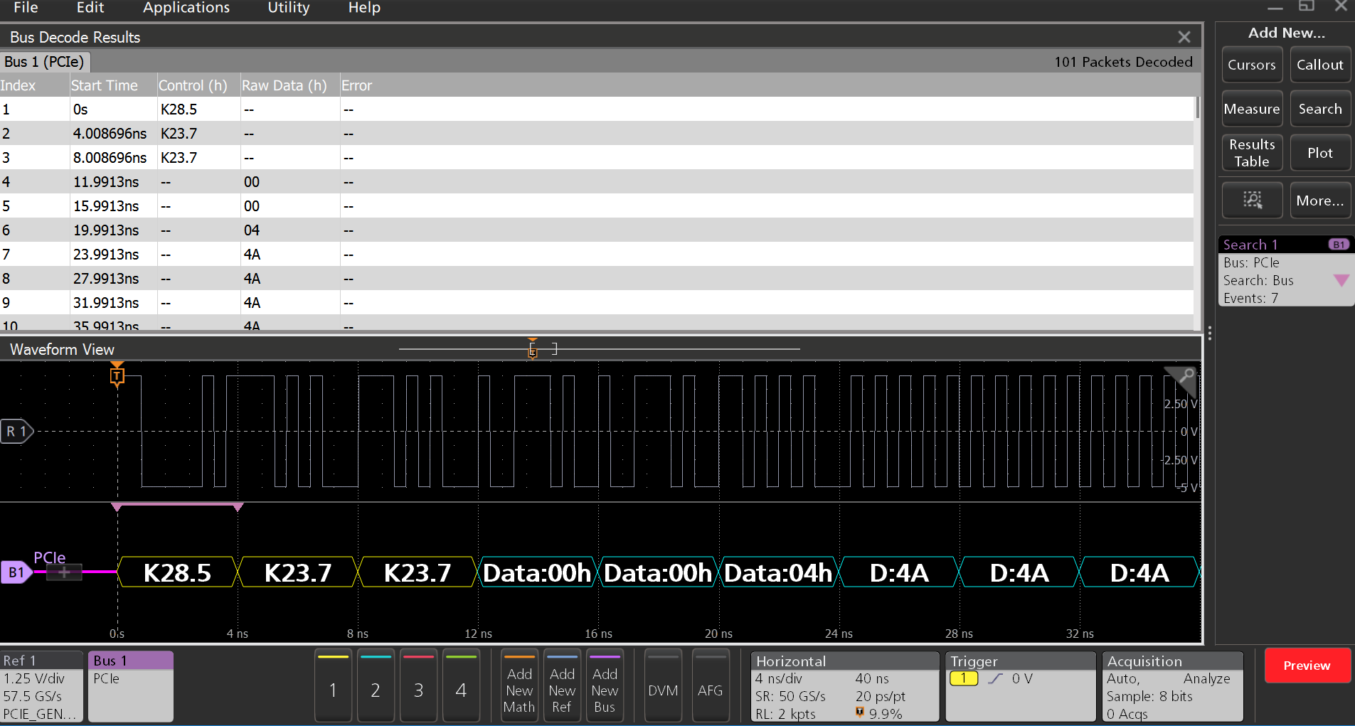
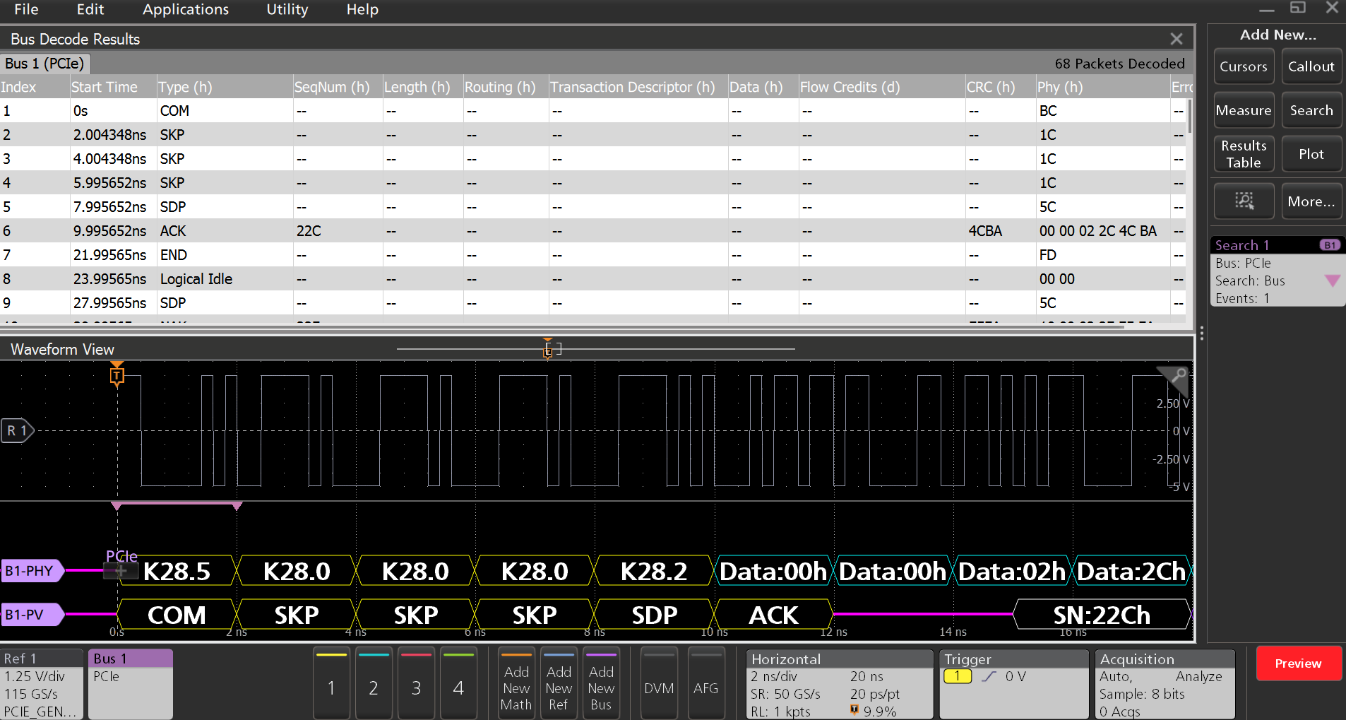
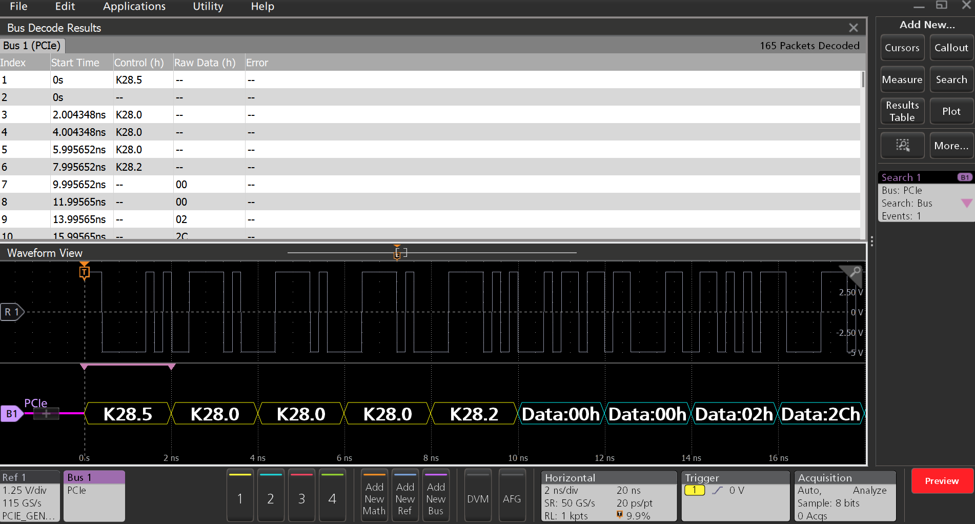
PCIe Characteristics (Gen 1, Gen 2, and Gen 3)
| Characteristic | Description |
|---|---|
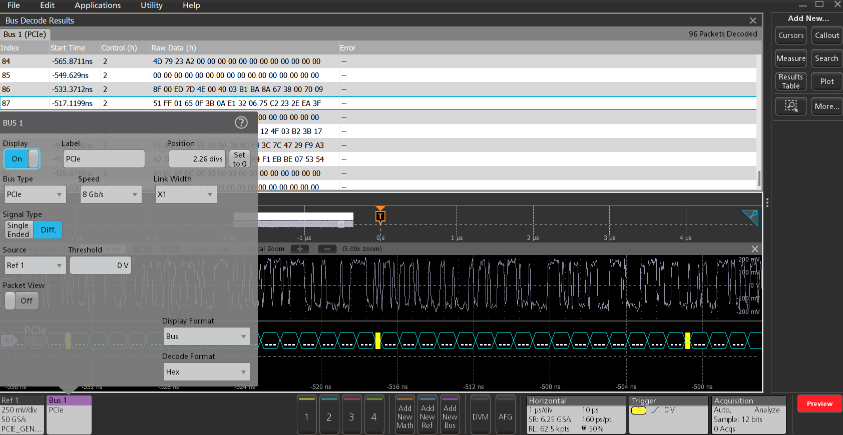
| PCIe Source(s) | Analog channels Digital channels Active Math channels Active Reference channels |
| Thresholds | Per-channel thresholds |
| Speed | 2.5 Gbps 5 Gbps 8 Gbps |
| Link Width | X1 |
| Packet View | On Off |
| Formats Available | Hex Binary Mixed Hex |
| Characteristic | Description |
|---|---|
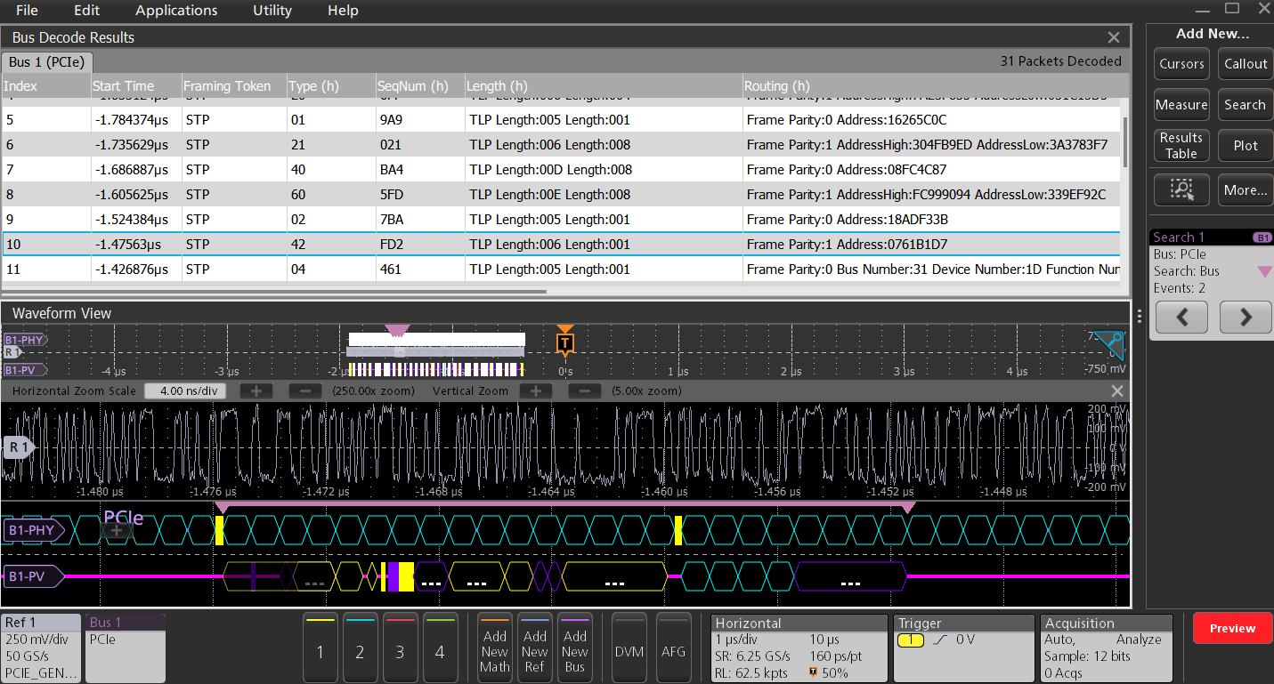
| Bus | Bus Bus and Waveforms |
| Results Table | Decoded packet data in a tabular view |
| Characteristic | Description |
|---|---|
| Search On |
|
PSI5 characteristics (Version 2.1)


| Characteristic | Description | |
|---|---|---|
PSI5 Sources | Analog channels Digital channels Active Math channels Active Reference channels | |
Thresholds | Per-channel thresholds | |
Recommended Probing | Sensor to ECU | Current probe with minimum current rating of less than 50mA - TCP2020, TCP202A |
ECU to Sensor | Differential Voltage probe - TDP1000, TDP1500, and TAP1500 | |
Direction | ECU to Sensor Sensor to ECU | |
| Direction -Sensor to ECU | Mode | Slow (83.3 kbps) Standard (125 kbps) Fast (189 kbps) |
Data A | 10 - 24 bits | |
Data B | 0 - 12 bits | |
Frame Control | 0 - 4 bits | |
Status | 0 - 3 bits | |
| Direction - ECU to Sensor | Sync Bit Period | 1 us to 300 us |
Sync Mode | Pulse Width Tooth Gap | |
Data Format | Nibble Byte | |
Decode Format | Hex Binary Mixed Hex | |
| Characteristic | Description |
|---|---|
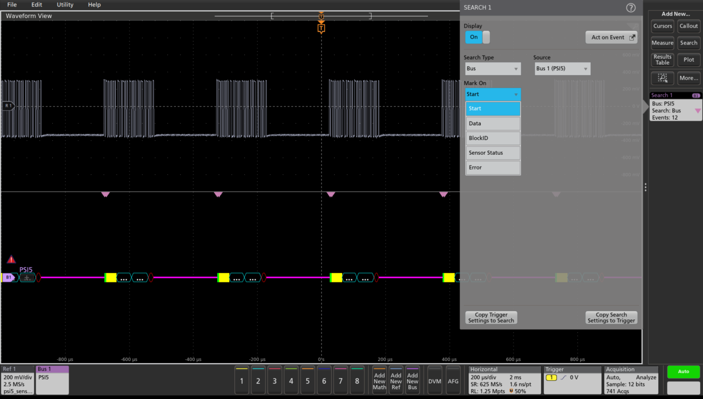
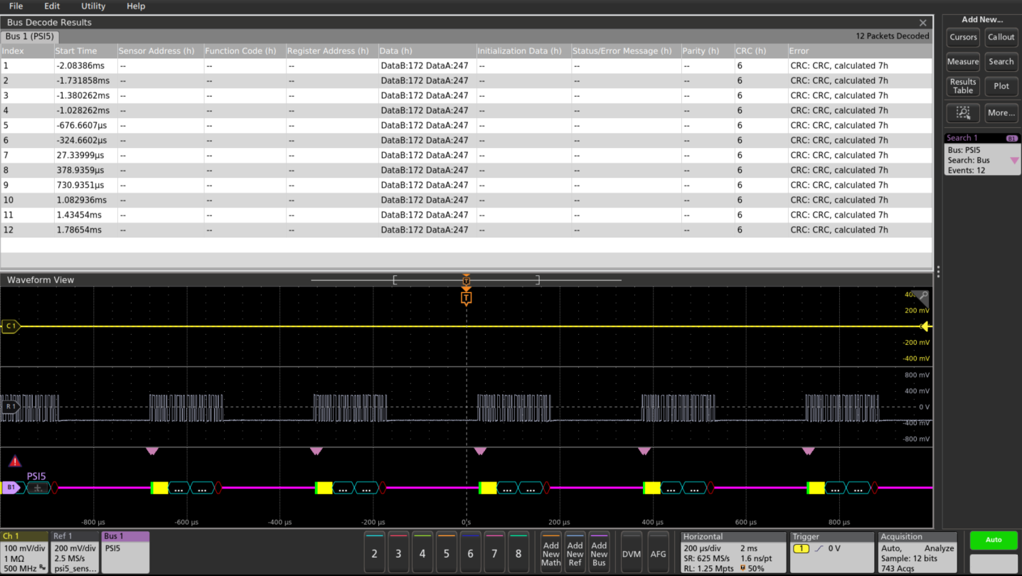
Bus | Bus only |
Bus and Waveforms | Simultaneous displays bus and digital waveforms |
Results Table | Decoded packet data in a tabular view |
| Characteristic | Description | |
|---|---|---|
Mark On | Direction - Sensor to ECU | Start [Start of packet] Status Data [Region B and Region A] Block ID Sensor Status [5 different status] Errors [Parity CRC and any] |
Direction - ECU to Sensor | Start [Start of packet] Status Data [4 or 8 bits] Function Code Sensor Address Register Address CRC Error | |
| Characteristic | Description | |
|---|---|---|
| Decode Display | Direction -Sensor to ECU Packets | Message Field (Yellow Field) Status (Yellow Field) Frame Control (Yellow Field) Data B (Cyan Field) Data A (Cyan Field) Parity or CRC (Purple Field) |
| Direction - ECU to Sensor Packets | Sensor Address (Yellow Field) Function Code (Yellow Field) Register Address (Yellow Field) Data (Cyan Field) CRC (Purple Field) | |
Error Type | Parity CRC Response Code (Sensor to ECU) | |
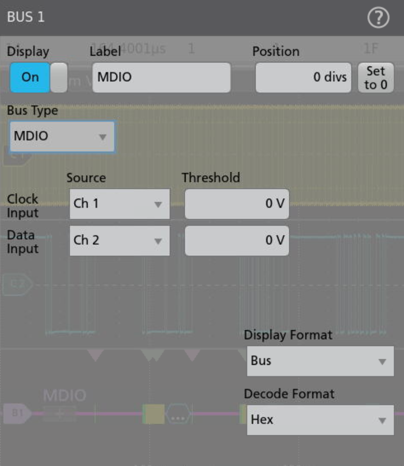
MDIO Characteristics
| Characteristic | Description |
|---|---|
| MDIO Sources (Clock, Data) | Analog channels Digital channels Active Math channels Active Reference channels |
| Thresholds | Pre-channel thresholds |
| Recommended Probing | Single-ended |
| Formats Available | Hex Binary Mixed Hex |
| Characteristic | Description |
|---|---|
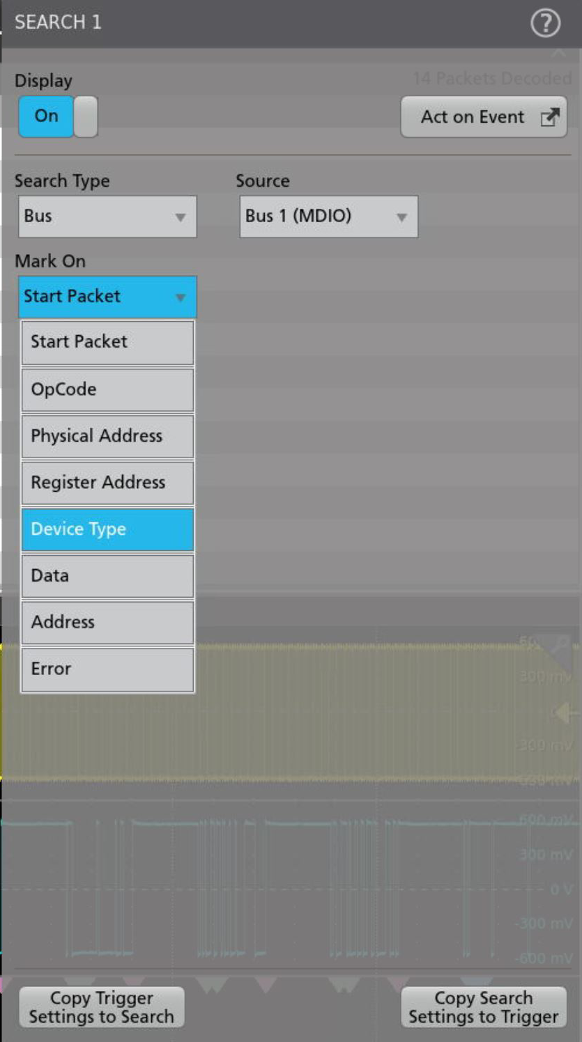
| Search On | Start Packet OpCode Physical Address Register Address Data Error: Any, OpCode Error, Device Type Error |
| Characteristic | Description |
|---|---|
| Bus | Bus only |
| Bus and Waveforms | Simultaneous display of bus and digital waveforms |
| Result Table | Decoded packet data in tabular view |
| Characteristic | Description |
|---|---|
| Maximum Clock/Data Rate | Maximum frequency of up to 2.5 MHz |
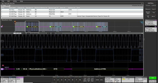
| Decode Display | Start Packet (Green) Clause (Green) OpCode (Yellow) Physical Address (Yellow) Register Address (Yellow) Device Type (Yellow) Data/Address (Cyan) Error: Any, OpCode Error, Device Type Error (Red) |
SVID characteristics (Version 1.9)
| Characteristic | Description |
|---|---|
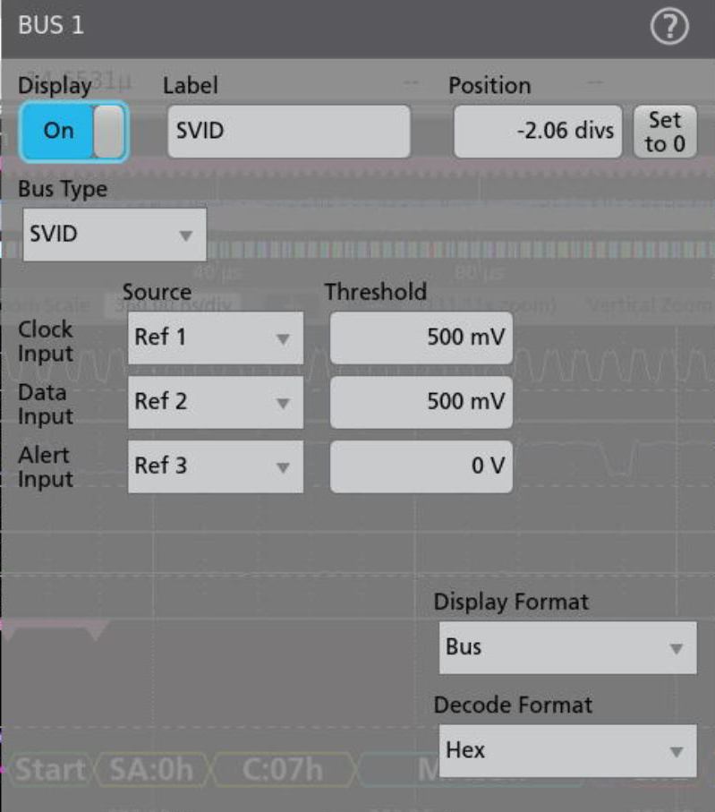
| SVID Sources (Clock, Data, Alert) | Analog channels Digital channels Active Math channels Active Reference channels |
| Thresholds | Pre-channel thresholds |
| Recommended Probing | Single-ended |
| Formats Available | Hex Binary Mixed Hex |
| Characteristic | Description |
|---|---|
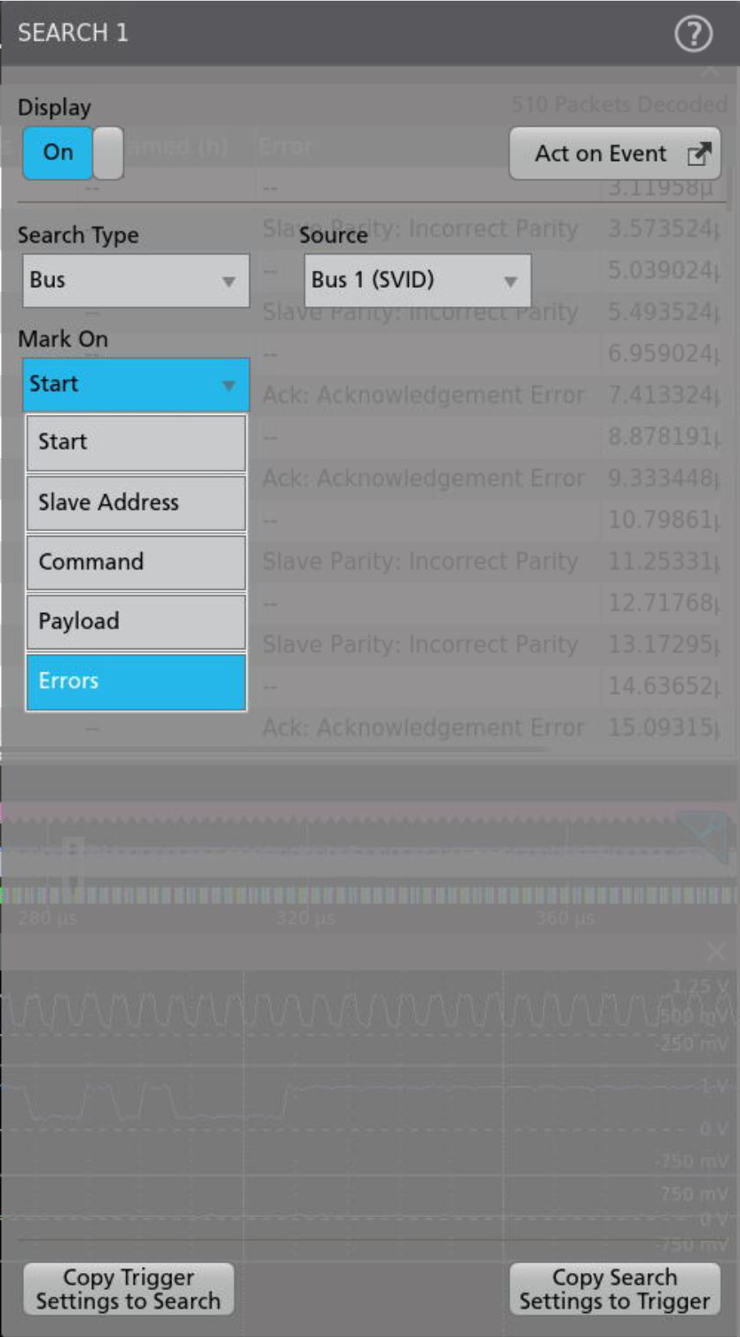
| Search On | Start Slave Address Command Payload: Master, Slave, Either Errors: Any, Missing Ack, Parity End |
| Characteristic | Description |
|---|---|
| Bus | Bus only |
| Bus and Waveforms | Simultaneous display of bus and digital waveforms |
| Result Table | Decoded packet data in tabular view |
| Characteristic | Description |
|---|---|
| Maximum Clock/Data Rate | Maximum frequency of 26.25 MHz |
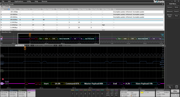
| Decode Display | Start (Green) Slave Address (Yellow) Command (Yellow) Master Payload (Cyan) Master Parity (Purple) End (Purple) Turnaround (Purple) Ack (Purple) Slave Payload (Cyan) Slave Parity (Purple) |
SVID (Trigger) characteristics
| Characteristic | Description |
|---|---|
| SVID Sources |
|
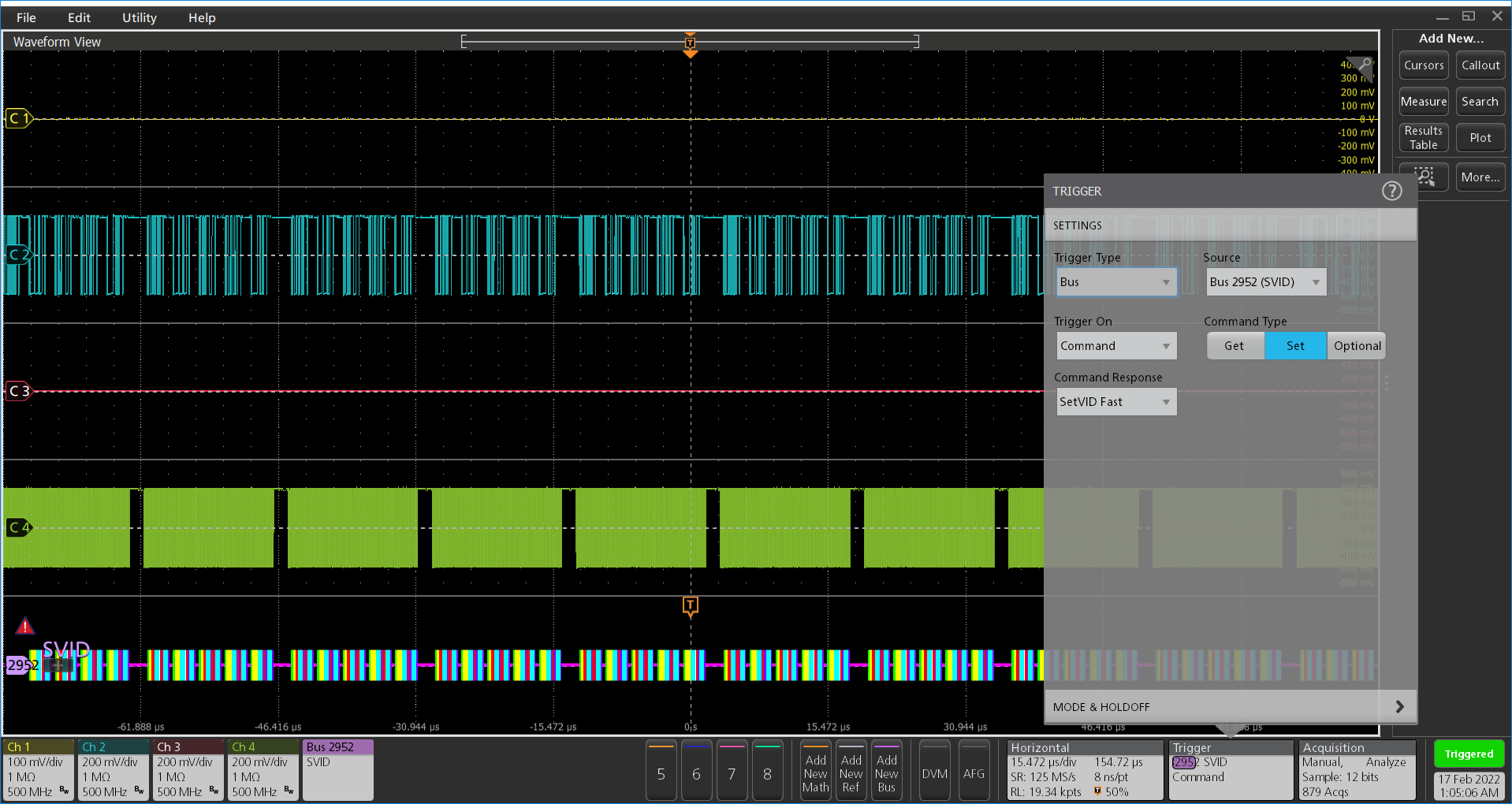
| Trigger On |
|
e-USB2 (Version 2.0)
| Characteristic | Description |
|---|---|
| Source(s) | Analog channels Digital channels(single-ended) Active Math channels Active Reference channels |
| Thresholds | Pre-channel thresholds |
| Speeds | Speed High Speed (480 Mb/s) Full Speed (12 Mb/s) Low Speed (1.5 Mb/s) |
| Recommended Probing, HS, LS, and FS | Single-ended [Active Single Ended TAP1500] |
| Formats Available | Mixed Hex Hex Binary Mixed ASCII |
| Characteristic | Description |
|---|---|
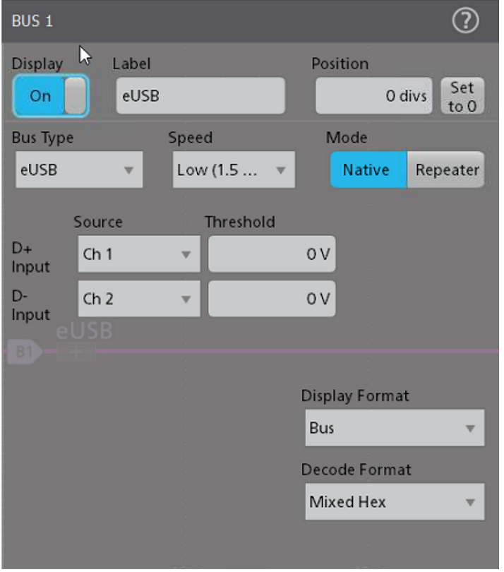
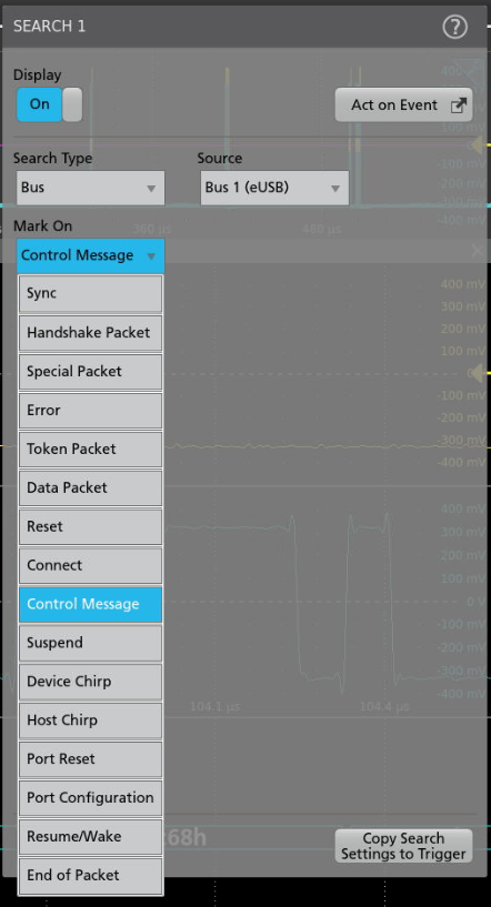
| Search On | Characteristic Description Search On Sync Reset Suspend Resume/Wake Connect Control Message Port Reset Port Configuration Device Chirp Host Chirp End of Packet Token (address) Packet Data Packet Handshake Packet: ACK, NAK, STALL, NYET (HS only) Special Packet: PRE (FS only), ERR, SPLIT, PING Reserved Error: PID check, CRC5 or CRC16, Bit stuffing (LS and FS only) |
| Characteristic | Description |
|---|---|
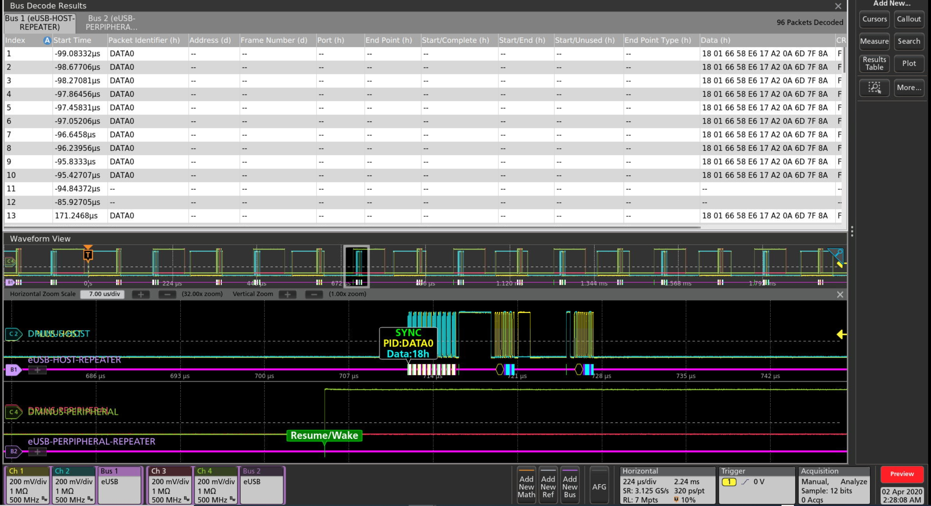
| Decode Display | Start of packet (green bar) Sync (green packet) PID (yellow packet) Token (address) (yellow packet) Data (cyan packet) CRC (purple packet) Error (red packet) End of packet (red bar) Control Message (Yellow packet) Zeros (Blue packet) Ack (Purple packet) Port Reset (Red Bar) Port Configuration(Green Bar) Connect (Green Bar) Resume/Wake(Green Bar) Device Chirp(Green Bar) Host Chirp (Green Bar) End Of reset(Red Bar) |
| Characteristic | Description |
|---|---|
Table view * Depends on the Model | View more than 10000* points |
| Save | Save Result table as CSV |
| Sessions | Save sessions of your protocol setup |
Simultaneous Buses * Depends on the Model | Load multiple Buses simultaneously* |
| Upcoming Future addition | Timing Measurements for Protocols |
| Search Table | Displays the Search hits along with Delta time difference between hits |
Manchester Characteristics (Line encoding)
| Characteristic | Description |
|---|---|
| Manchester Sources | Analog channels Digital channels(single-ended) Active Math channels Active Reference channels |
| Bus Setup: Threshold Idle Bits Transition For ‘0’ Tolerance |  |
| Recommended Probing | Differential/Single ended |
| Formats Available | Hex Binary |
| Packet View |  |
| Characteristic | Description |
|---|---|
| Search On | Characteristic Description Search On Sync Reset Suspend Resume/Wake Connect Control Message Port Reset Port Configuration Device Chirp Host Chirp End of Packet Token (address) Packet Data Packet Handshake Packet: ACK, NAK, STALL, NYET (HS only) Special Packet: PRE (FS only), ERR, SPLIT, PING Reserved Error: PID check, CRC5 or CRC16, Bit stuffing (LS and FS only) |
| Characteristic | Description |
|---|---|
| Bus | Bus Only |
| Bus and Waveforms | Simultaneous display of bus and digital waveforms |
| Results Table | Decoded packet data in a tabular view with columns containing: Sync Pattern Packet Header Packet Data Packet Trailer Error |
| Characteristic | Description |
|---|---|
| Maximum Clock/Data Rate | 1Gbps |
| Decode Display | Control Field (yellow packet) Payload Field (cyan packet) |
| Error Handling | Parity Manchester |
| Search On | When Packet View is ON Sync Bits Header Data Trailer Errors When Packet View is OFF Data Errors |
| Characteristic | Description | |
|---|---|---|
| Search On (Packet View ON) | Sync Bits Header Data Trailer Errors |  |
| Search On (Packet View OFF) | Data Errors |  |
| Characteristic | Description |
|---|---|
| Table view * Depends on the Model | View more than 10000* points |
| Save | Save Result table as CSV |
| Results Table | Sessions |
| Simultaneous Buses * Depends on the Model | Load multiple Buses simultaneously* |
| Upcoming Future addition | Timing Measurements for Protocols |
| Search Table | Displays the Search hits along with Delta time difference between hits |
DPHY(DSI2.0/CSI2.0) Characteristics (Version 2.0)
| Characteristic | Description |
|---|---|
| DPHY Sources | Analog channels Math channels Active Reference channels |
| Salient Features | Decode capability in for CSI/DSI protocols. Decode capability for Escape mode. Decode capability for High speed burst mode. Decode capability for 8b9b line encoding in LPDT and HS mode. Search capability for SoT/EoT Search capability for long and short packets Search capability for Escape mode Search capability for Errors like ECC, CRC, and Any |
| Bus Setup |  |
| Recommended Probing | Clock – Single Ended/Differential Data – Single Ended Single ended probe: No. of probes: 3 (D+ and D- by default) Differential probe: No. of probes: Not supported |
| 8b9b encoding mode | Select line encoding in LPDT and HS mode. |
| Formats Available | Hex Binary Mixed Hex |
| Characteristic | Description |
|---|---|
| Bus | Bus Only |
| Bus and Waveforms | Simultaneous display of bus and digital waveforms |
| Result Table | Decoded packet data in a tabular view with columns containing: Mode Data Type Virtual Identifier ECC Data CRC End Error |
| Characteristic | Description |
|---|---|
| Maximum Clock/Data Rate | 2.5 Gbps |
| Decode Display | Control Field (yellow) ECC/CRC (Green) Pixel Fields (Red,Green,Blue,Yellow) Data Symbol (cyan) Raw Fields (Cyan) |
| Error Handling | ECC CRC SOT Sync |
| Characteristic | Description |
|---|---|
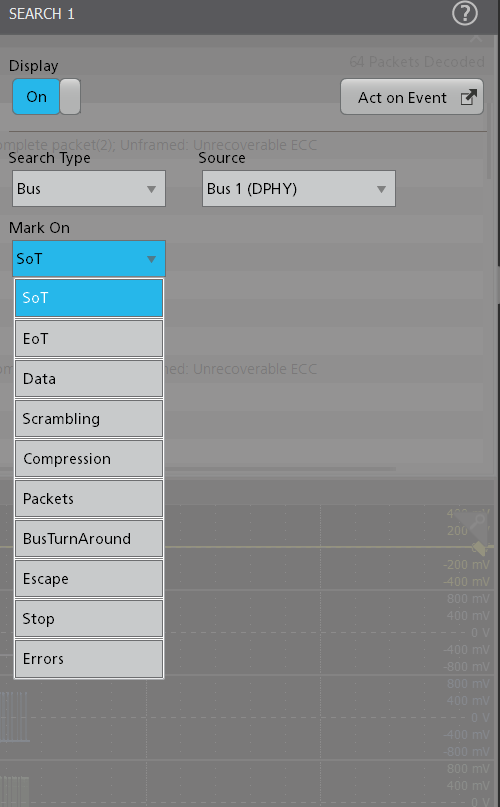
| Search On (CSI/DSI) | SoT – It searches SoT of each transmission in HS mode EoT – It searches EoT of each transmission in HS mode. Data – Data search (HS/LP) Scrambling – Search for scrambling mode command Compression – Search for Compression mode command. **Packets – Searches for Short and long packets Escape – Search for Escape entry mode STOP – Search for Escape mode exit Errors – Search for CRC and ECC errors. **Can select from the list of standard packet names |
| Characteristic | Description |
|---|---|
Table view * Depends on the Model | View more than 10000* points |
| Save | Save Result table as CSV |
| Sessions | Save sessions of your protocol setup |
Simultaneous Buses * Depends on the Model | Load multiple Buses simultaneously* |
| Upcoming Future addition | Timing Measurements for Protocols |
| Search Table | Displays the Search hits along with Delta time difference between hits |
SDLC Characteristics (Version GA27-3093-3)
| Characteristic | Description |
|---|---|
| SDLC Source(s) | Analog channels Digital channels Active Math channels Active Reference channels |
| Thresholds | Pre-channel thresholds |
| Recommended Probing | Differential |
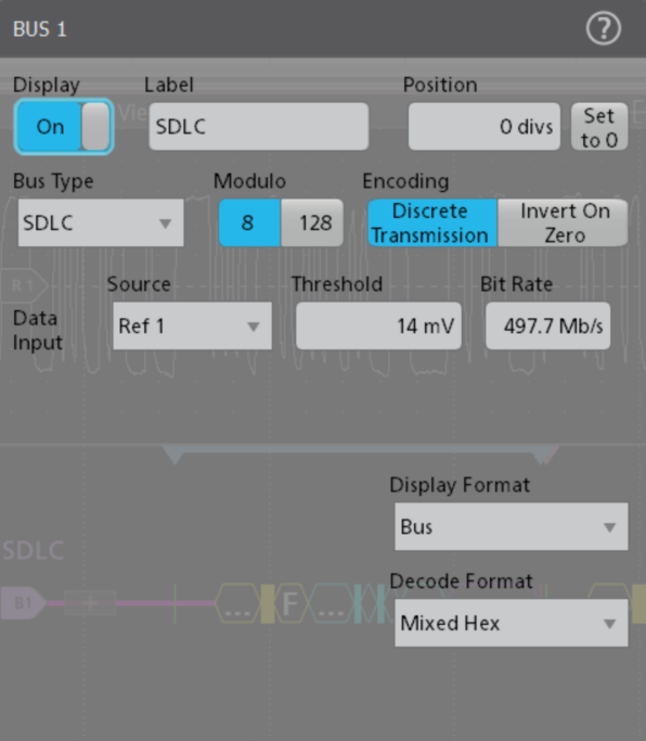
| Modulo | 8 [8-bit Control Word] 128 [16-bit Control Word] |
| Encoding | Discrete Transmission [NRZ] Invert On Zero [Inverted NRZi] |
| Formats Available | Hex Binary Mixed Hex |
| Characteristic | Description |
|---|---|
| Bus | Bus Only |
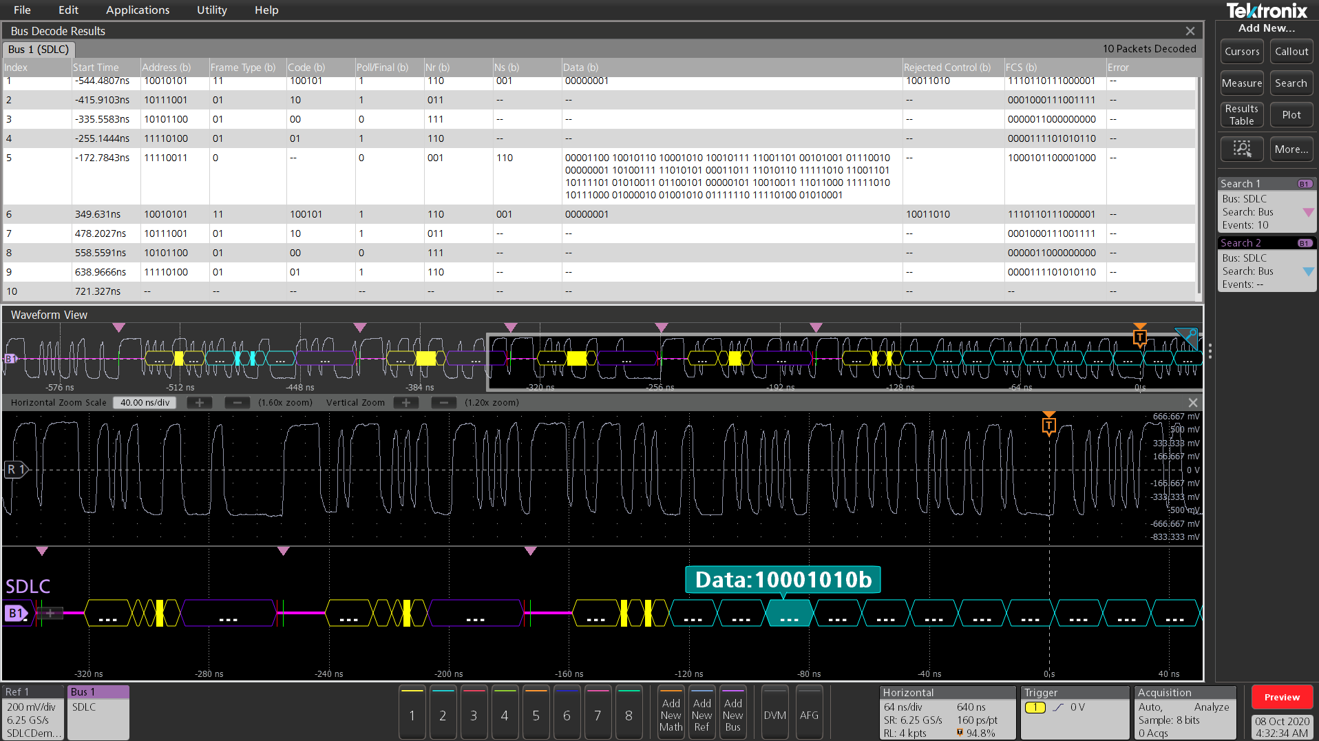
| Result Table | Decoded packet data in a tabular view |
| Characteristic | Description |
|---|---|
| Maximum Clock/Data Rate | 1 Gbits/sec |
| Decode Display | Start (green vertical line) Address (yellow field) Frame Type (yellow field) Code (yellow field) Ns(yellow field) [Sequence number sent] Nr(yellow field) [Sequence number received] Poll/Final (yellow field) Data(cyan field) FCS(purple field) Abort (red vertical line) |
| Error handling | FCS [ Frame Check Sequence Errors] |
| Characteristic | Description |
|---|---|
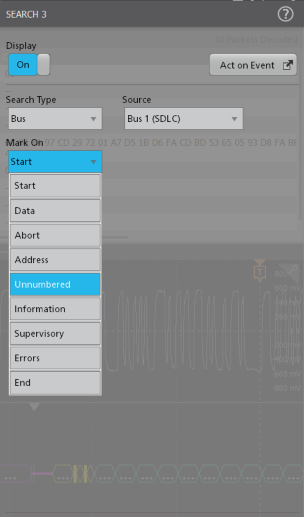
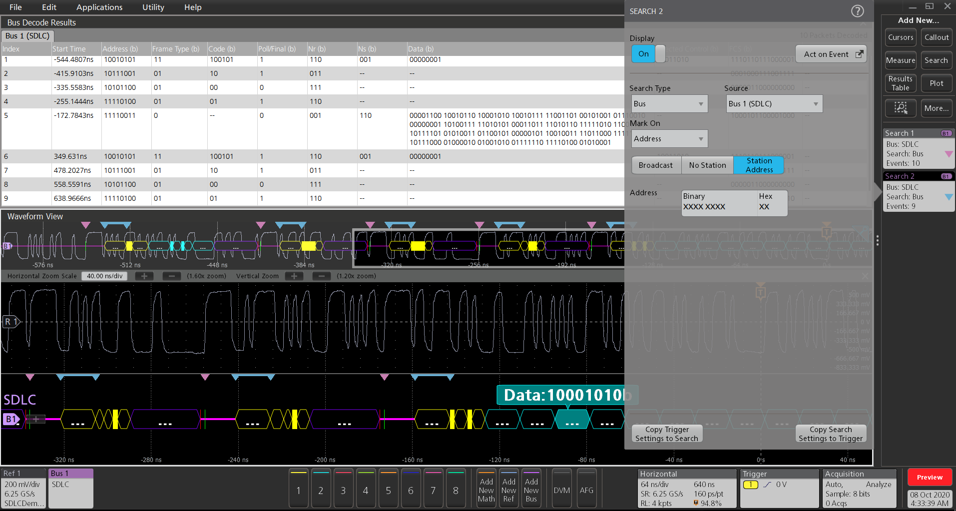
| Search On | Start [Searches for Start event] Data [Searches for Payload Data] Abort [Searches for Abort] Address Broadcast [Broadcast Packets] No Station [Packets not pertaining to secondary] Station [Valid Station Address] Unnumbered Commands [Searches for Primary Commands] Responses [Searches for Secondary Responses] Both Information [Searches for information frames] Supervisory [Searches for different receiver status] Receive Frame Ready Receive Frame Not Ready Reject frame Errors FCS [Searches for Frame Check Sequence errorrs] Out of Numeric Order [Searches for this frame] Stop |
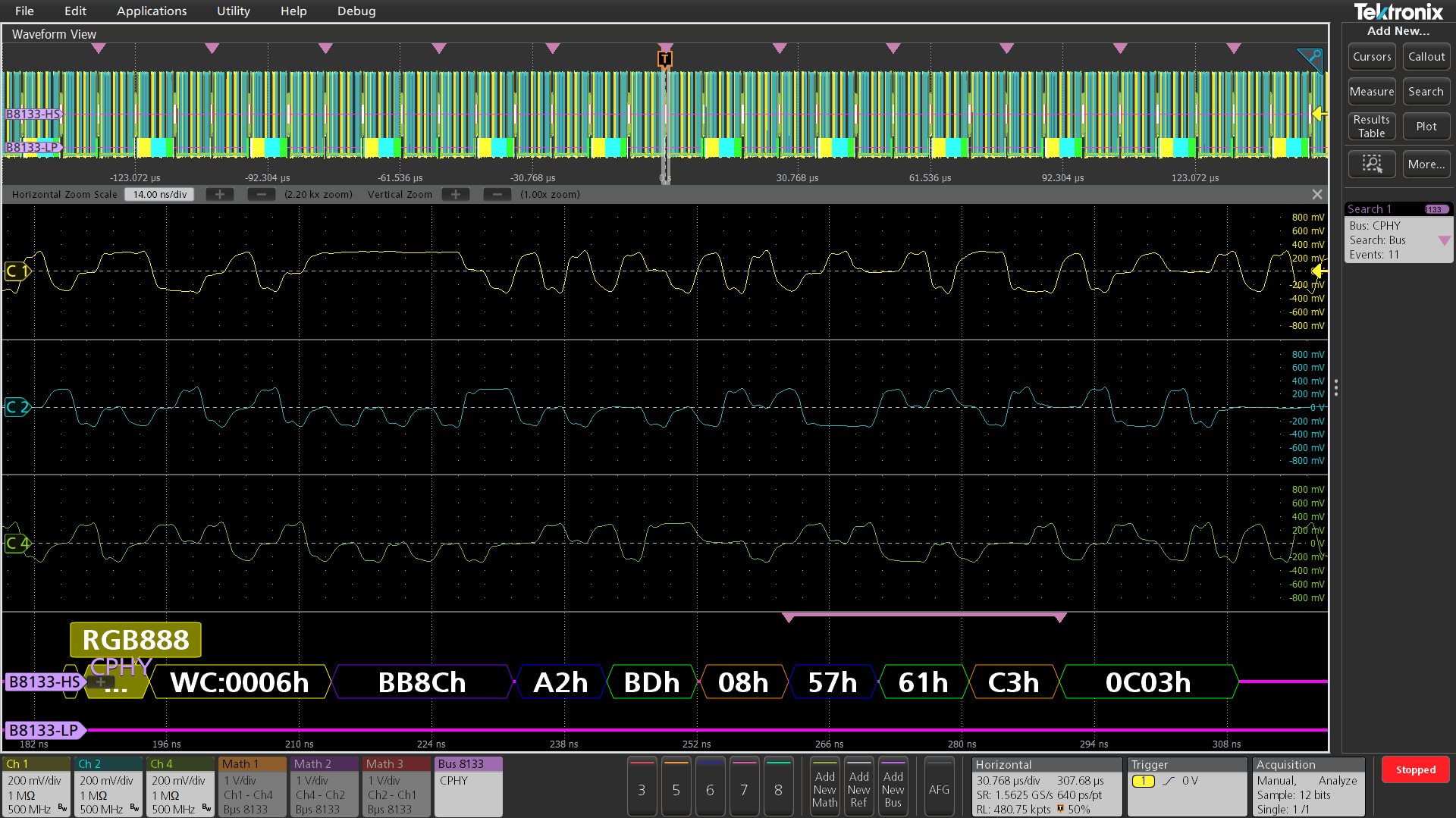
CPHY Characteristics (Version 2.0)
| Characteristic | Description |
|---|---|
| CPHY Sources | Analog channels Digital channels Math channels Active reference channels |
| Salient Features | Decode capability in for CSI/DSI protocols. Decode capability for Escape mode. Decode capability for High speed burst mode. Decode capability for Word/Symbol Mode. Decode capability in single ended and differential mode Search capability for SoT/EoT Search capability for long and short packets Search capability for Escape mode Search capability for CRC Errors Search capability on Pixel value and Pixel number in CSI/DSI packet search |
| Sub Type | CSI DSI Word (16 Bit data word decode) Symbol (Symbol level decode of cphy data) |
| Signal Type | Single Ended: No. of probes: 3 Differential: No. of probes: 5 Minimum BW of probe: As minimum bitrate of HS is set to 4 Mbps, almost all probe should work. But considering the general CPHY HS speed is about 1 GHz and speed can vary depending on customer, the probe need to based on what speed the end customer want to test. |
| Formats Available | Hex Binary Mixed Hex |
| Bit Rate | Specifies the data rate in High Speed Mode |
| Characteristic | Description |
|---|---|
| Bus | Bus Only |
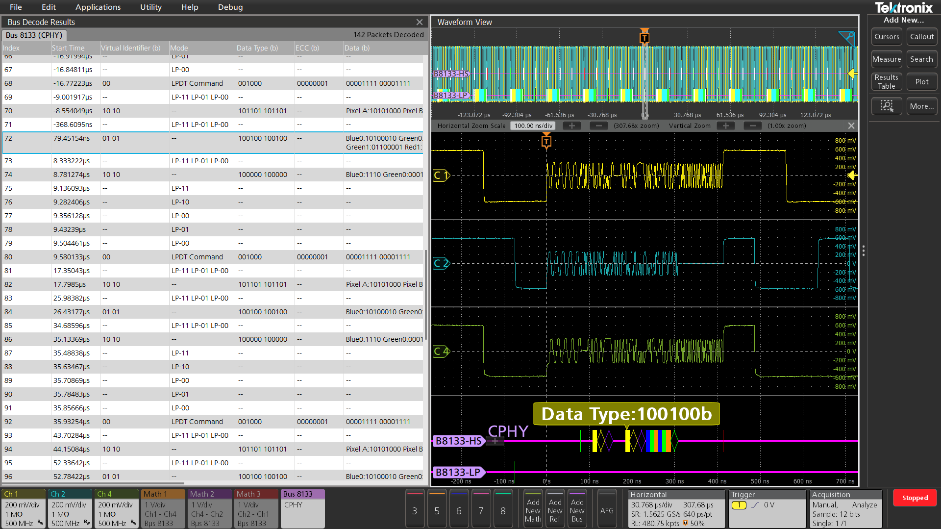
| Result Table | Decoded packet data in a tabular view with columns containing: Mode Data Type Virtual Identifier PHCCRC Data CRC Symbols End Error |
| Characteristic | Description |
|---|---|
| Maximum Clock/Data Rate | 10 Gbps |
| Decode Display | Control Field (yellow) ECC/CRC (Green) Pixel Fields (Red, Green, Blue, Yellow) Data Symbol (cyan) Raw Fields (Cyan) Word and Symbol Decode (cyan) |
| Error Handling | PHCRC CRC SOT Sync |
| Sub type | CSI (CSI packet decode) DSI (DSI packet decode in HS/LP) Word (16 bit word decode) Symbol Decode |
| Characteristic | Description |
|---|---|
Search On (CSI/DSI) | SoT – Searches SoT of each transmission in HS mode EoT – Searches EoT of each transmission in HS mode. Data – Data search (HS/LP) Scrambling – Search for scrambling mode command Compression – Search for Compression mode command. |
| Characteristic | Description |
|---|---|
**Packets – Searches for Short and long packets Escape – Search for Escape entry mode Errors – Search for CRC and PHCRC errors. **Can select from the list of standard packet names | |
| Word / Symbols Decode | Search for Words/Symbols respectively |
ONEWIRE Characteristics
| Characteristic | Description |
|---|---|
| 1-WIRE Sources | Analog channels Digital Channels Active Math channels Active Reference channels |
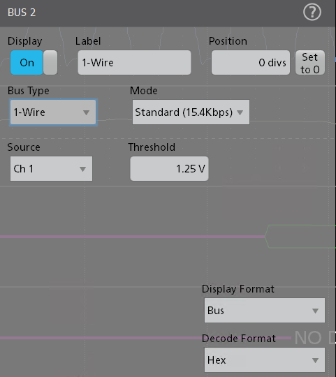
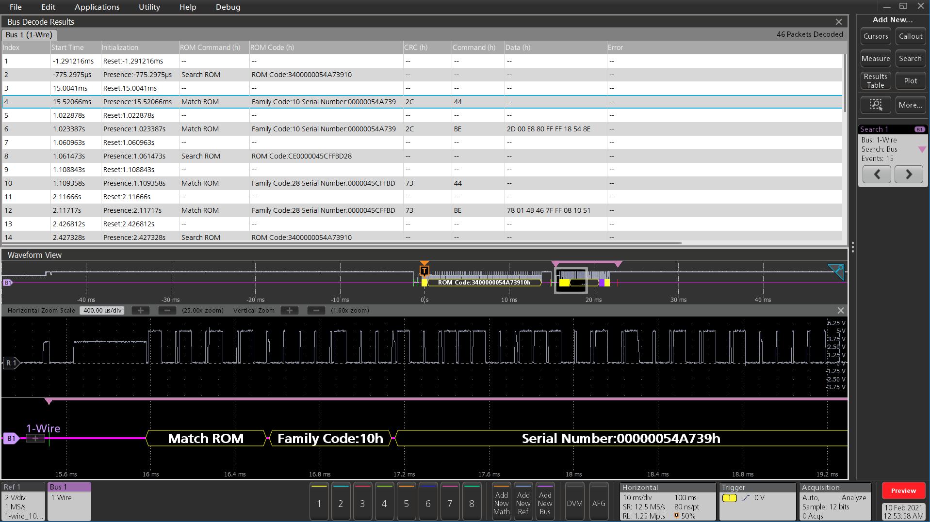
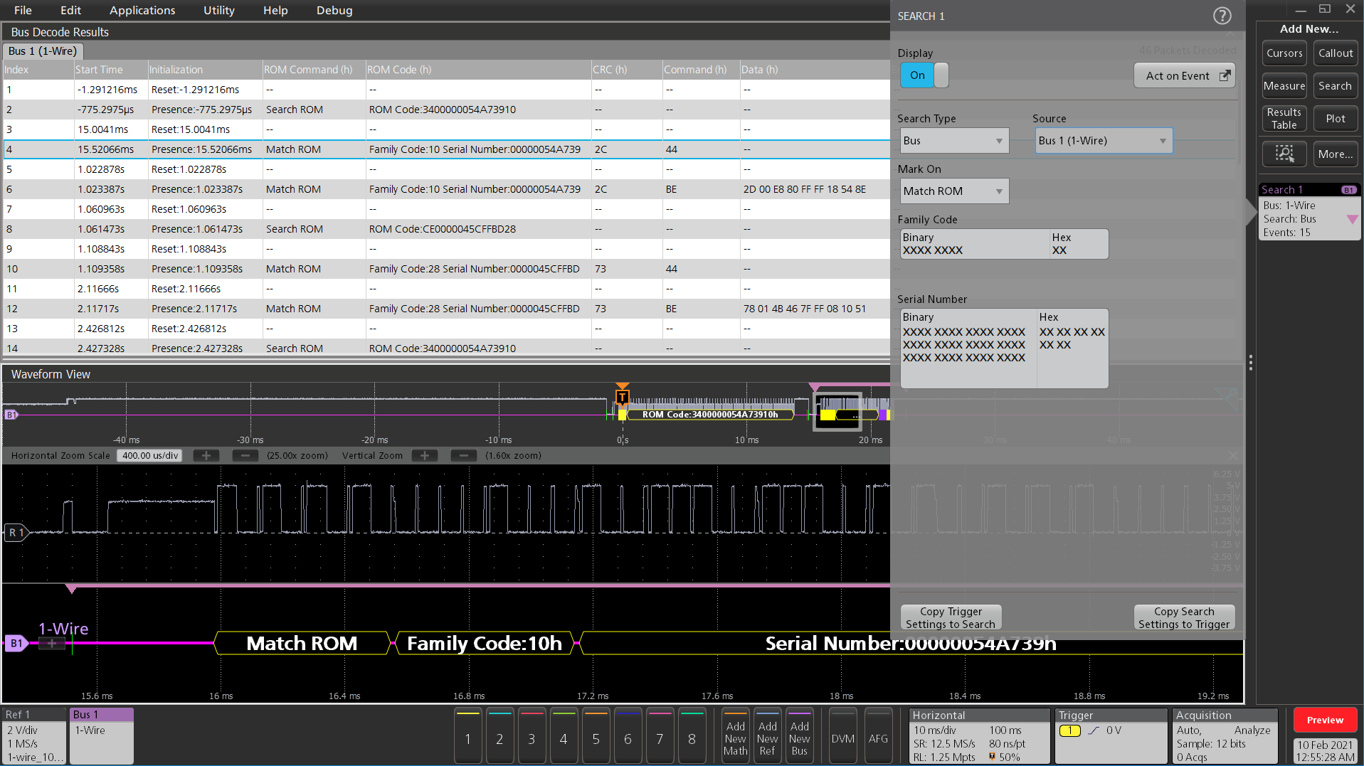
| Salient Features | Decode capability in for 1-WIRE protocol. Decode capability for Standard mode. Decode capability for Overdrive mode. Search capability for Reset, Presence events Search capability for Command, Data Search capability for different ROM packets such as Read/Match/Skip/Search ROM and Alarm based on the Standard or Overdrive mode chosen. Search capability for CRC Error |
| Formats Available | Hex Binary Mixed Hex |
| Mode | Specifies the mode of operation – Standard (15.4 kbits/s) or Overdrive (125 kbits/s). |
| Recommended Probing | Single Ended passive probe Differential passive probe |
| Characteristic | Description |
|---|---|
| Bus | Bus Only |
| Result Table | Decoded packet data in a tabular view with columns containing: Initialization ROM Command ROM Code CRC Command Data Error |
| Characteristic | Description |
|---|---|
| Decode Display | ROM Command/ROM Code/Command (yellow) CRC (purple) Reset/Presence event (Green) End event (Red) |
| Error Handling | CRC |
| Characteristic | Description |
|---|---|
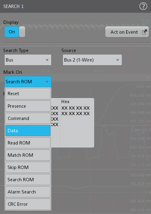
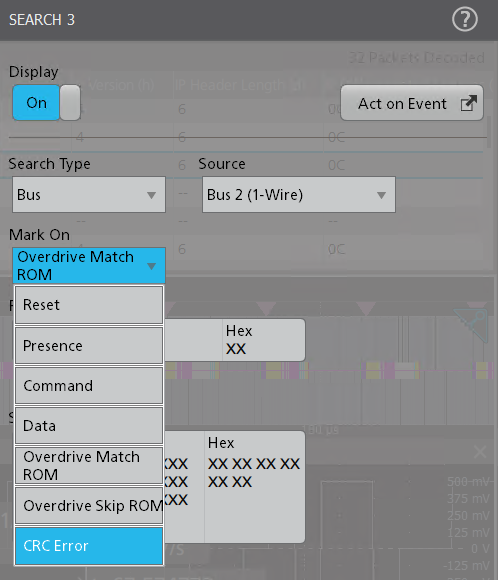
Search On 1-WIRE | Reset – Searches for the Reset event. Reset is the default trigger on condition. Presence – Searches for the Presence event. Command – Searches for Command. Data – Searches for the Data. Read ROM – Searches for the Family code and Serial number of Read ROM. Match ROM – Searches for the Family code and Serial number of Match ROM. Overdrive Match ROM – Searches for the Family code and Serial number of Match ROM. Skip ROM – Searches for Skip ROM packet. Overdrive Skip ROM – Searches for the Overdrive Skip ROM packet. Search ROM – Searches for the ROM code. Alarm Search – Searches for the Alarm packet. CRC Error specifies the search condition as CRC Error. |
CXPI characteristics (Version: JASO D 015-3: 2014/J3076_201510)
| Characteristic | Description |
|---|---|
| CXPI sources (signal source) |
|
| Recommended Probes | It is a low speed protocol with voltage between 1.8 V-3.3 V
|
| Product differentiator | Display IBS bits on decoded bus for Inter byte spacing clarity. |
| Salient features | CXPI source has recessive threshold level for signal decode. i.e. TH(rec) is 70% peak-to-peak of the signal. Transmitting node transmits data to the communication bus, it transmits to encoding circuit after converting the data to UART format. |
| Formats available | Hex Binary Mixed Hex |
| Bit rate | Specifies the data rate up to 20 kbs for CXPI bus decode. |
| Characteristic | Description |
|---|---|
| Bus | Bus only |
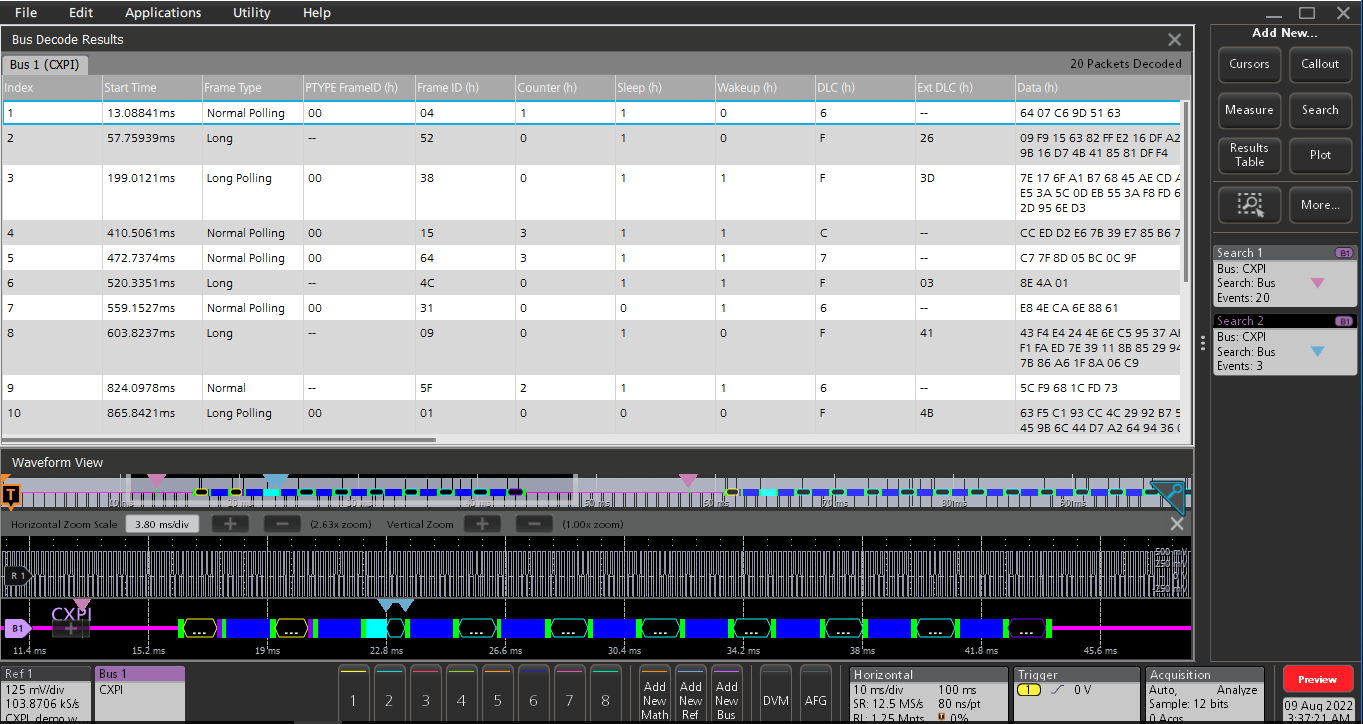
| Result table | Decoded packet data in a tabular view with columns containing:
|
| Result table |
|
| Characteristic | Description |
|---|---|
| Maximum Clock/Data Rate | 20 kbs |
| Decode Display |
|
| Error Handling |
|
| Characteristic | Description |
|---|---|
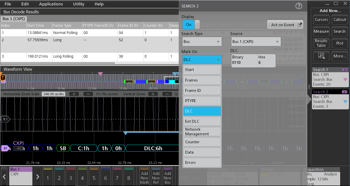
| Search On |
|
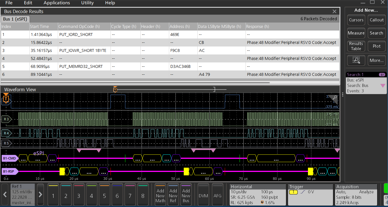
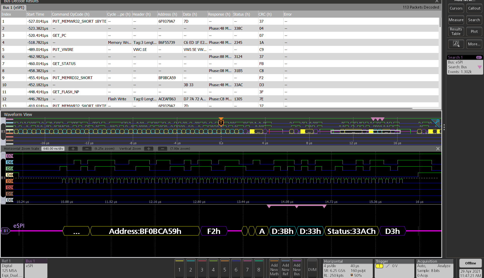
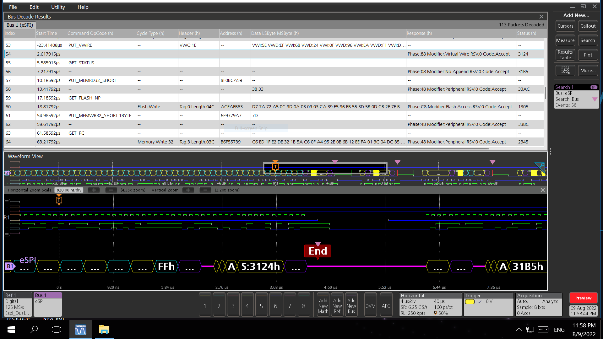
Enhanced serial peripheral interface (eSPI) characteristics (Version 1.0)
| Characteristic | Description |
|---|---|
| eSPI Sources |
|
| Salient features |
Further, search capability for Command phase based on different channel related command opcodes and Response phase based on with/without header. Both phases support sub field search based on corresponding cycle type. Search capability for Errors based on the phase: CRC/Cycle type/Command opcode/Defer/Fatal/Non-Fatal/No Response. |
| Formats Available | Hex Binary Mixed Hex |
| I/O Mode | Specifies the mode of operation:
|
| Alert | Optional Alert channel- off by default |
| Polarity | Specifies the polarity of the input sources |
| Channels required for decode | 4+1 (Clock, Chip Select, Command Input, Response Input + Alert) |
| Recommended Probes | It is a low speed protocol with voltage between 1.8 V-3.3 V
|
| Differentiators |
|
| Characteristic | Description |
|---|---|
| Single Mode (Default) |  |
| Dual Mode |  |
| Characteristic | Description |
|---|---|
| Bus | Bus only |
| Result Table | Decoded packet data in a tabular view with columns containing:
|
| Characteristic | Description |
|---|---|
| Decode Display | Start (Green) Command OpCode, Response, Virtual Wire Count/Group/Index, Cycle Type, Tag, Length, Message Code, SMBus Slave address/Source address/Destination address/Source slave address/OpCode, Byte Count, MCTP, Destination Point, Source Point, SOM, EOM, PEC, Latency Scale, Message Tag, TO, PktSeq, Wait (Yellow) Data, Double Word, Virtual Wire Data (Cyan) CRC (Purple) Stop, Response error, Unframed (Red) |
| Error Handling | CRC, Defer, Fatal, Non-Fatal, No Response, Command OpCode, Cycle type |
| Characteristic | Description |
|---|---|
| Search On eSPI | Start: Enables to search the start event of the packet decode. Channel Independent: Enables search on Channel Independent command and responses packets. |
| Search On eSPI | Peripheral Channel: Enables search on different types of Peripheral channel command and responses packets. OOB Channel: Enables search on different Out-Of-Band (OOB) channel command and Responses packets. Virtual Wire Channel: Enables search on different Virtual Wire channel command and responses packets. Flash Access Channel: Enables search on different Flash access channel command and responses packets. Wait: Enables to search on the wait state that appears after the TAR window. End: Enables to search on the End events when the packet decode ends. Phase: Select the type of phase between command and response for which to search. Command: Enables search on the command opcode of different channels specified under the mark on. Response: Enables to search on the response field. Response With Header: Enables to search on the RSP opcode that consists of a Response Code and a Response Modifier. Response Without Header: Enables to search on the RSP opcode that consists of a Response Code and a Response Modifier. Command Opcode: Enables search on the command opcode of different channels. Cycle Type: Enables search under command and response with header based on different cycle types for different channels. Address: Enables search on the address field for different channels based on different commands and response with header classified based on cycle types. Tag: Enables search on the tag field for different channels based on different commands and response with header classified based on cycle types. |
| Search On eSPI | Length: Enables search on the length field for different channels based on different commands and response with header classified based on cycle types. SMBus Slave Address: Enables search on SMBus Slave address under the OOB channel. Virtual Wire Count: Enables search on Virtual Wire Count for command and response with header under the virtual wire channel. Virtual Wire Index: Enables search on Virtual Wire index for command and response with header under the virtual wire channel. Virtual Wire Data: Enables search on Virtual Wire Data for command and response with header under the virtual wire channel. Data Bytes: Sets the number of data bytes for which to search. Data: Sets the data value for which to search. Searches based on command and response. Status: Enables search on the status field of the response packets. Error Type: Sets the error type for which to search based on command or response phase. |
| Mark On and Channel Independent |  |
| Mark On and Channel Independent |    |
| Mark On and Channel Independent |    Peripheral, OOB, and Virtual Wire Channel |
| Mark On and Channel Independent |  |

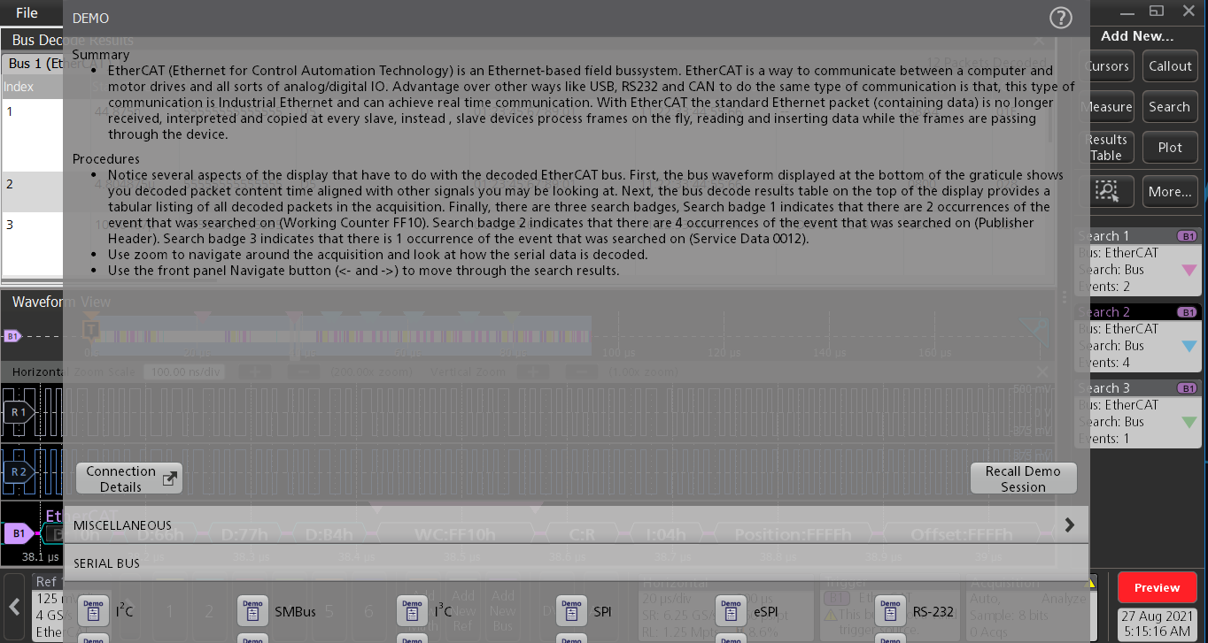
EtherCAT characteristics
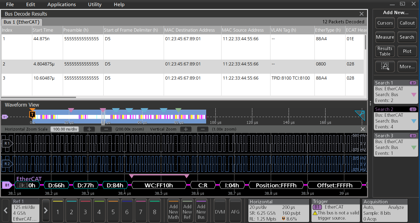
| Characteristic | Description |
|---|---|
Ethernet sources | Analog channels Digital channels Active math channels Active reference channels |
| Salient features | Decode capability for EtherCAT protocol in both single ended and differential modes |
| Bus setup (Single-Ended) |  |
| Bus setup (Differential) |  |
Formats available | Hex Binary Mixed Hex |
Signal Type | Single ended (default) Differential |
| Characteristic | Description |
|---|---|
| Bus | Bus only |
| Results table | Decoded packet data in a tabular view with columns containing:
Frame Check Sequence |
Decode display | Green: Start of frame Yellow: MAC source address, MAC destination address, EtherType Gray: TPID, TCI, UDP Source Port, UDP Destination Port, Length, Checksum, Command, Index, Position, Offset, Address, Reserved, Circulating Frame, More EtherCAT datagrams, IRQ, Working Counter, PublisherID, Network Variable Count, Channel, Priority, Type Dark Pink: IP VersionHL, IP Service, IP Total Length, IP Identification, IP Flags, IP Fragment Offset, IP Time To Live , IP Protocol, IP Header Checksum, IP Source Address, IP Destination Address, Length, Reserved, Type, Padding, Hash, Quality Cyan: Data, Detail, Publisher Header Red: End |
| Error handling | FCS error |
| Characteristic | Description |
|---|---|
| Search On | Start: Select to search on Start of Frame. Protocol: Select to search on Protocol Types and then Frame type of each Protocol respectively. IP Header: Select to search on IP Header based on Identification, Source, and Destination Address Values. UDP Header: Set the 16-bit Source Port that you want to search. MAC Address: Select to search on Packets having the combination of Source and Destination Address Values. Tag Control Information: Sets the 16-bit tag control information that you want to search. EtherCAT Header Length: Sets the 11-bit ethercat header length that you want to search. Datagram: Select to search on sub-fields of datagram including Datagram Header, Data, and Working Counter. Network Variable: Select to Search on sub-fields of network variable including Publisher Header, NV Header, and Data. Mailbox: Select to search on sub-fields of mailbox including Mailbox Header, Service Data, and Error Reply Service Data. FCS Error: Select to search on FCS Error if any. End of Frame: Select to search on end of frames. |
SMBus characteristics
| Characteristic | Description |
|---|---|
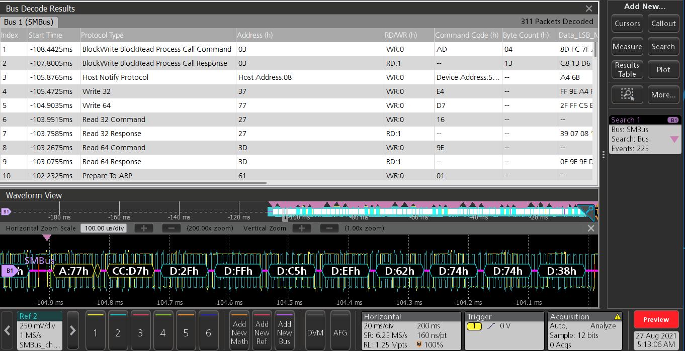
SMBus sources | Analog channels Digital channels Active math channels Active reference channels |
Salient features | Decode capability for SMBus protocol with PEC Byte as optional. Search capability for Start, Repeated Start, Stop, and Idle events. Search capability for addresses such as Host Address, Device Address, and Address. Search capability for Command Code, Data and UDID Data. Search capability for Errors – Any, ACK, NACK. |
| Bus setup |  |
| PEC Byte as True |  |
Formats available | Hex Binary Mixed |
| PEC | Optional PEC Byte – False as default |
| Characteristic | Description |
|---|---|
| Bus | Bus only |
| Results table | Decoded packet data in a tabular view with columns containing:
PEC |
Decode Display | Green: Start, Repeated Start Yellow: Address, Host Address, Device Address, Slave Address, Device Slave Address, Assigned Address, Targeted Slave Address, Read, Write, Read/Write, Command Code, Byte Count, Bit, Idle Cyan: Data, Device Capabilities, Version Revision, Interface, Vendor ID, Device ID, Subsystem Vendor ID, Subsystem Device ID, Vendor Specific ID Purple: PEC Red: End |
| Error Handling | Any, ACK, NACK |
| Characteristic | Description |
|---|---|
| Search On | Start: Select to search on the start events. Repeated Start: Select to search on the repeated start events. Address: Sets the 7-bit address pattern that you want to search. Host Address: Select to search on the host address. Device Address: Set the 7-bit device address that you want to search. Command Code: Sets the 8-bit command code that you want to search. Data: Sets the data pattern that you want to search. Data Bytes: Sets the number of data bytes that you want to search (1 to 8 bytes). Field Bytes: Sets the field bytes as 1, 2, or 4 for UDID Data. UDID Data: Sets the UDID data that you want to search. Error Type: Sets the error bytes that you want to search. You can search on ANY, ACK, NACK, and PEC errors (PEC error search is available only when the PEC Byte in SMBus bus configuration is set as True). Stop: Select to search on the stop events. Idle: Select to search on the idle events. |
Ordering information
Protocol Bundles
Specially designed SW bundles with 1 year renewable and perpetual to suit your Design and validation needs.
Validate your Protocols with our industry standard Serial analysis software available for over 30 technologies.
Pro bundle for Serial Analysis teams. Our standards expertise and Integrated Protocol Decoders help you shorten your design cycle, gain greater technical insight and improve team productivity to bring new products and services to market much faster.
| Serial Decode | Description | 4 Series MSO | 5 Series MSO | 6 Series MSO |
|---|---|---|---|---|
| 4-RL-1 | Record length enhancement to 62.5 million sample points . | ✔ | ✖ | ✖ |
| 5-RL-125M | Record length enhancement to 125 million sample points . | ✖ | ✔ | ✖ |
| 6-RL-2 | Record length enhancement to 250 million sample points . | ✖ | ✖ | ✔ |
| SRAUDIO | Audio Serial Triggering and Analysis (I2S, LI, RJ, TDM). Enables triggering on packet-level information on serial audio buses. | ✔ | ✔ | ✔ |
| SRAUTO | Automotive Serial Triggering and Analysis (CAN, CAN FD, CAN XL, LIN, FlexRay). Enables triggering on packet-level information on CAN/CAN FD/CAN XL/LIN/FelxRay. | ✔ | ✔ | ✔ |
| SRNET | Ethernet Serial Triggering and Analysis (10BASE-T, 100BASE-T). Enables decoding and analysis on Ethernet buses. | ✔ | ✔ | ✔ |
| SRI3C | I3C Serial Decoding and Analysis. Enables decoding and searching on packet-level information on MPI I3C. | ✔ | ✔ | ✔ |
| SRNRZ | NRZ Serial Decoding and Analysis. Supports NRZ with normal and inverted polarity with Bit order (MSB or LSB first). | ✔ | ✔ | ✔ |
| SRPM | Power Management Serial Triggering and Analysis. Enables triggering on packet-level information on SPMI buses. | ✔ | ✔ | ✔ |
| SRUSB2 | USB 2.0 Serial Triggering and Analysis. Enables triggering on packet-level information on USB 2.0 buses. | ✔ | ✔ | ✔ |
| SRUSB3 | USB 3.0, USB 3.1 Gen 1, USB 3.2 Gen 1 Serial Decoding and Analysis. Extensive search options. | ✖ | ✖ | ✔ |
| SRPCIE321 | PCIe Serial Decoding and Analysis. Extensive search options. | ✖ | ✖ | ✔ |
| SRMDIO | MDIO Protocol Decoder and Search. Extensive search options. | ✔ | ✔ | ✔ |
| SRSVID | SVID Protocol Decider and Search. Supports version rev.1.92. Extensive search options | ✔ | ✔ | ✔ |
| SR8B10B | 8B10B Serial Decoding and Analysis. Finds and displays parity error if found in 4-bit or 6-bit for the 10-bit symbol in 8b10b | ✖ | ✔ | ✔ |
| SRETHERCAT | ETHERCAT Protocol Decoder and search. Enables decoding and analysis on EtherCAT buses. | ✔ | ✔ | ✔ |
| SRSMBUS | SMBUS Protocol Decoder and search. Enables decoding and analysis on SMbus buses. | ✔ | ✔ | ✔ |
| 1 Year License | 4-PRO-SERIAL-1Y | 5-PRO-SERIAL-1Y | 6-PRO-SERIAL-1Y | |
| Perpetual License | 4-PRO-SERIAL-PER | 5-PRO-SERIAL-PER | 6-PRO-SERIAL-PER | |
Pro Bundle for Military and Aerospace designers. Our Software design tools help you shorten your design cycle, gain greater technical insight and improve team productivity to bring new products and services to market much faster.
| Serial Decode | Description | 4 Series MSO | 5 Series MSO | 6 Series MSO |
|---|---|---|---|---|
| 4-RL-1 | Record length enhancement to 62.5 million sample points. | ✔ | ✖ | ✖ |
| 5-Rl-125M | Record length enhancement to 125 million sample points. | ✖ | ✔ | ✖ |
| 6-RL-2 | Record length enhancement to 250 million sample points. | ✖ | ✖ | ✔ |
| SRAERO | Aerospace Serial Triggering and Analysis (MIL-STD-1553, ARINC429). Enables triggering on packet-level information. | ✔ | ✔ | ✔ |
| SRSPACEWIRE | SpaceWire serial analysis. Enables decoding and analysis on SpaceWire buses. | ✔ | ✔ | ✔ |
| MTM | ✔ | ✔ | ✔ | |
| SRNRZ | NRZ Serial Decoding and Analysis. Supports NRZ with normal and inverted polarity with Bit order (MSB or LSB first). | ✖ | ✔ | ✔ |
| DJA | Jitter Analysis Package including TIE, Eye diagram, Histogram and other advanced analysis measurements. | ✔ | ✔ | ✔ |
| 1 Year License Perpetual License | 4-PRO-MILGOV-1Y | 5-PRO-MILGOV-1Y | 6-PRO-MILGOV-1Y | |
| 4-PRO-MILGOV-PER | 5-PRO-MILGOV-PER | 6-PRO-MILGOV-PER | ||
To add to an instrument at purchase
| Serial bus type | 3 Series MDO Option | 4 Series MSO Option | 5 Series MSO Option | 6 Series MSO Option | Description |
|---|---|---|---|---|---|
| MIL-STD-1553, ARINC 429 | 3-SRAERO | 4-SRAERO | 5-SRAERO | 6-SRAERO | Aerospace Serial Triggering and Analysis (MIL-STD-1553, ARINC 429). Enables triggering on packet-level information on MIL-STD-1553 and ARINC 429 buses as well as analytical tools such as digital views of the signal, bus views, packet decoding, search tools, and packet decode tables with time stamp information. |
| I2S, LJ, RJ, TDM | 3-SRAUDIO | 4-SRAUDIO | 5-SRAUDIO | 6-SRAUDIO | Audio Serial Triggering and Analysis (I2S, LJ, RJ, TDM). Enables triggering on packet-level information on serial audio buses as well as analytical tools such as digital views of the signal, bus views, packet decoding, search tools, and packet decode tables with time stamp information. |
| 8b10b | N/A | N/A | 5-SR8B10B | 5-SR8B10B | 8B10B Serial Decoding and Analysis. Enables decoding and searching the packet-level information on buses with analytical tools such as digital views of the signal, bus views, packet decoding, search tools, and packet decode tables with time stamp information. Finds and displays parity error if found in 4-bit or 6-bit for the 10-bit symbol in 8b10b. |
| NRZ | N/A | 4-SRNRZ | 5-SRNRZ | 6-SRNRZ | NRZ Serial Decoding and Analysis. Enables decoding and searching the packet-level information on buses with analytical tools such as digital views of the signal, bus views, packet decoding, search tools, and packet decode tables with time stamp information. Variants like NRZ-I, NRZ-M, NRZ-S, and NRZ-C are not supported currently. Supports only NRZ with normal and inverted polarity with Bit Order (MSB or LSB First). |
| CAN, CAN FD, CAN XL, LIN, FlexRay | 3-SRAUTO (Except CAN XL) | 4-SRAUTO | 5-SRAUTO | 6-SRAUTO | Automotive Serial Triggering and Analysis (CAN, CAN FD, CAN XL, LIN, FlexRay). Enables triggering on packet-level information on CAN/CAN FD/CAN XL/LIN/FlexRay buses as well as analytical tools such as digital views of the signal, bus views, packet decoding, search tools, and packet decode tables with time stamp information. |
| Automotive 10BASE-T1S, 100BASE-T1 | N/A | N/A | 5-SRAUTOEN1 | 6-SRAUTOEN1 | 10BASE-T1S Serial trigger with decoder and 100Base-T1 Automotive Ethernet serial decode. Includes analytical tools such as digital views of the signal, bus views, packet decoding, search tools, and packet decode tables with time stamp information. |
| SENT | N/A | 4-SRAUTOSEN | 5-SRAUTOSEN | 6-SRAUTOSEN | Automotive Sensor Serial Triggering and Analysis (SENT). Enables triggering on packet-level information on SENT buses as well as analytical tools such as digital views of the signal, bus views, packet decoding, search tools, and packet decode tables with time stamp information. |
| RS-232/422/485, UART | 3-SRCOMP | 4-SRCOMP | 5-SRCOMP | 6-SRCOMP | Computer Serial Triggering and Analysis (RS-232, RS-422, RS-485, UART). Enables triggering on packet-level information on RS-232/422/485 and UART buses as well as analytical tools such as digital views of the signal, bus views, packet decoding, search tools, and packet decode tables with time stamp information. |
| I 2C, SPI | 3-SREMBD | 4-SREMBD | 5-SREMBD | 6-SREMBD | Embedded Serial Triggering and Analysis (I2C, SPI). Enables triggering on packet-level information on I2C and SPI buses as well as analytical tools such as digital views of the signal, bus views, packet decoding, search tools, and packet decode tables with time stamp information. |
| Ethernet | N/A | 4-SRENET | 5-SRENET | 6-SRENET | Ethernet Serial Triggering and Analysis (10BASE-T, 100BASE-T). Enables triggering on packet-level information on Ethernet buses as well as analytical tools such as digital views of the signal, bus views, packet decoding, search tools, and packet decode tables with time stamp information. |
| I3C | N/A | 4-SRI3C | 5-SRI3C | 6-SRI3C | I3C Serial Decoding and Analysis. Enables decoding and searching on packet-level information on MIPI I3C buses with analytical tools such as digital views of the signal, bus views, packet decoding, search tools, and packet decode tables with time stamp information. |
| SPMI | N/A | 4-SRPM | 5-SRPM | 6-SRPM | Power Management Serial Triggering and Analysis (SPMI). Enables triggering on packet-level information on SPMI buses as well as analytical tools such as digital views of the signal, bus views, packet decoding, search tools, and packet decode tables with time stamp information. |
| Spacewire | N/A | 4-SRSPACEWIRE | 5-SRSPACEWIRE | 6-SRSPACEWIRE | Spacewire serial analysis. Enables decoding and analysis on Spacewire buses. |
| USB 2.0 | 3-SRUSB2 | 4-SRUSB2 | 5-SRUSB2 | 6-SRUSB2 | USB 2.0 Serial Triggering and Analysis. Enables triggering on packet-level information on USB 2.0 buses as well as analytical tools such as digital views of the signal, bus views, packet decoding, search tools, and packet decode tables with time stamp information. |
| USB 3.0 | N/A | N/A | N/A | 6-SRUSB3 | USB serial triggering and analysis (USB 3.0) for 6 Series oscilloscopes. |
| USB 3.1 Gen 1 | N/A | N/A | N/A | 6-SRUSB3 | USB serial triggering and analysis (USB 3.1 (Gen 1, 2*)) for 6 Series oscilloscopes, * appears when upgrade is available. |
| USB 3.2 Gen 1 | N/A | N/A | N/A | 6-SRUSB3 | USB serial triggering and analysis (USB 3.2 (Gen 1, 2*)) for 6 Series oscilloscopes, * appears when upgrade is available. |
| Serial options bundle | 3-BND | N/A | N/A | N/A | Adds all serial analysis options and the power analysis option available for an instrument. |
| PCIe | N/A | N/A | N/A | 6-SRPCIE321 | PCIe serial decoding and analysis (PCIe Gen 1/Gen 2/Gen 3) for 6 Series B oscilloscope. |
| PSI5 | N/A | 4-SRPSI5 | 5-SRPSI5 | 6-SRPSI5 | PSI5 Serial Decoding (v1.3 and 2.1) and analysis. Enables decoding and Search Packet level information with analytical tools such as digital views of the signal, bus views, packet decoding, search tools, and packet decode tables with time stamp information. |
| MDIO | N/A | 4-SRMDIO | 5-SRMDIO | 6-SRMDIO | MDIO Protocol Decoder and Search, No Hardware Trigger; Node locked |
| SVID | N/A | 4-SRSVID | 5-SRSVID | 6-SRSVID | SVID Protocol Decoder and Search, No Hardware Trigger; Node locked |
| e-USB2 | N/A | 4-SREUSB2 | 5-SREUSB2 | 6-SREUSB2 | eUSB2 Protocol Decoder and Search; Node locked |
| DPHY | N/A | N/A | 5- SRDPY | 6- SRDPY | DPHY CSI/DSI (DSI2.0 /CSI2.0 protocols decoder. Supports HS data transmission burst, and escape mode functionality. Data transmission can be with 8-bit raw data or using 8b9b encoded symbol |
| MANCHESTER | N/A | 4-SRMANCH | 5-SRMANCH | 6-SRMANCH | Supports Generic Manchester decode. Decode of packets as per packet structure defined. Decode of Errors like Sync, Parity, Manchester |
| SDLC | 4-SRSDLC | 5-SRSDLC | 6-SRSDLC | SDLC decoder and Search. Extensive search options on captured waveforms like unnumbered , Supervisory, address etc | |
| CPHY 1.2 | N/A | N/A | 5-SRCPHY | 6-SRCPHY | MIPI C-PHY CSI/DSI Protocol Decoder and Search |
| 1-Wire | N/A | 4-SRONEWIRE | 5-SRONEWIRE | 6-SRONEWIRE | 1-Wire Protocol Decoder and search |
| eSPI | N/A | 4-SRESPI | 5-SRESPI | 6-SRESPI | eSPI Protocol Decoder and search |
| CXPI | N/A | 4-SRCXPI | 5-SRCXPI | 6-SRCXPI | CXPI Protocol Decoder and search |
| ETHERCAT | N/A | 4-SRETHERCAT | 5-SRETHERCAT | 6-SRETHERCAT | ETHERCAT Protocol Decoder and search |
| SMBUS | N/A | 4-SRSMBUS | 5- SRSMBUS | 6- SRSMBUS | SMBUS Protocol Decoder and search |
| NFC | N/A | 4-RFNFC | 5-RFNFC | 6-RFNFC | NFC protocol decode and search |
To upgrade an already purchased instrument
| Serial bus 3 | 3 Series MDO Node-Locked License 4 | 4 Series MSO Node-Locked/Floating License | 5 Series MSO Node-Locked/Floating License | 6 Series MSO Node-Locked/Floating License |
|---|---|---|---|---|
| MIL-STD-1553, ARINC 429 | SUP3 SRAERO | SUP4-SRAERO SUP4-SRAERO-FL | SUP5-SRAERO SUP5-SRAERO-FL | SUP6-SRAERO SUP6-SRAERO-FL |
| I2S, LJ, RJ, TDM | SUP3 SRAUDIO | SUP4-SRAUDIO SUP4-SRAUDIO-FL | SUP5-SRAUDIO SUP5-SRAUDIO-FL | SUP6-SRAUDIO SUP6-SRAUDIO-FL |
| CAN, CAN FD, CAN XL, LIN, FlexRay | SUP3 SRAUTO (Except CAN XL) | SUP4-SRAUTO SUP4-SRAUTO-FL | SUP5-SRAUTO SUP5-SRAUTO-FL | SUP6-SRAUTO SUP6-SRAUTO-FL |
| 8B10B | N/A | N/A | SUP5-SR8B10B SUP5-SR8B10B-FL | SUP6-SR8B10B SUP6-SR8B10B-FL |
| NRZ | N/A | SUP4-SRNRZ SUP4-SRNRZ-FL | SUP5-SRNRZ SUP5-SRNRZ-FL | SUP6-SRNRZ SUP6-SRNRZ-FL |
| 10BASE-T1S, 100BASE-T1 Automotive Ethernet | N/A | N/A | SUP5-SRAUTOEN1 SUP5-SRAUTOEN1-FL | SUP6-SRAUTOEN1 SUP6-SRAUTOEN1-FL |
| SENT | N/A | SUP4-SRAUTOSEN SUP4-SRAUTOSEN-FL | SUP5-SRAUTOSEN SUP5-SRAUTOSEN-FL | SUP6-SRAUTOSEN SUP6-SRAUTOSEN-FL |
| RS-232/422/485, UART | SUP3 SRCOMP | SUP4-SRCOMP SUP4-SRCOMP-FL | SUP5-SRCOMP SUP5-SRCOMP-FL | SUP6-SRCOMP SUP6-SRCOMP-FL |
| I2C, SPI | SUP3 SREMBD | SUP4-SREMBD SUP4-SREMBD-FL | SUP5-SREMBD SUP5-SREMBD-FL | SUP6-SREMBD SUP6-SREMBD-FL |
| Ethernet | N/A | SUP4-SRENET SUP4-SRENET-FL | SUP5-SRENET SUP5-SRENET-FL | SUP6-SRENET SUP6-SRENET-FL |
| I3C | N/A | SUP4-SRI3C SUP4-SRI3C-FL | SUP5-SRI3C SUP5-SRI3C-FL | SUP6-SRI3C SUP6-SRI3C-FL |
| SPMI | N/A | SUP4-SRPM SUP4-SRPM-FL | SUP5-SRPM SUP5-SRPM-FL | SUP6-SRPM SUP6-SRPM-FL |
| Spacewire | N/A | SUP4-SRSPACEWIRE SUP4-SRSPACEWIRE | SUP5-SRSPACEWIRE SUP5-SRSPACEWIRE-FL | SUP6-SRSPACEWIRE SUP6-SRSPACEWIRE-FL |
| USB 2.0 | SUP3 SRUSB2 | SUP4-SRUSB2 SUP4-SRUSB2-FL | SUP5-SRUSB2 SUP5-SRUSB2-FL | SUP6-SRUSB2 SUP6-SRUSB2-FL |
| USB 3.0 | N/A | N/A | N/A | SUP6-SRUSB3 SUP6-SRUSB3-FL |
| USB 3.1 Gen 1 | N/A | N/A | N/A | SUP6-SRUSB3 SUP6-SRUSB3-FL |
| USB 3.2 Gen 1 | N/A | N/A | N/A | SUP6-SRUSB3 SUP6-SRUSB3-FL |
| Serial analysis bundle 5 | SUP3 BND | N/A | N/A | N/A |
| PCIe Gen 1/Gen 2/Gen 3 | N/A | N/A | N/A | SUP6-SRPCIE321 SUP6-SRPCIE321-FL |
| PSI5 | N/A | SUP4-SRPSI5 SUP4-SRPSI5-FL | SUP5-SRPSI5 SUP5-SRPSI5-FL | SUP6-SRPSI5 SUP6-SRPSI5-FL |
| MDIO | N/A | SUP4-SRMDIO SUP4-SRMDIO-FL | SUP5-SRMDIO SUP5-SRMDIO-FL | SUP6-SRMDIO SUP6-SRMDIO-FL |
| SVID | N/A | SUP4-SRSVID SUP4-SRSVID-FL | SUP5-SRSVID SUP5-SRSVID-FL | SUP6-SRSVID SUP6-SRSVID-FL |
| e-USB2 | N/A | SUP4-SREUSB2 SUP4-SREUSB2-FL | SUP5-SREUSB2 SUP5-SREUSB2-FL | SUP6-SREUSB2 SUP6-SREUSB2-FL |
| DPHY | N/A | N/A | SUP5-SRDPHY SUP5-SRDPHY -FL | SUP6-SRDPHY SUP6-SRDPHY-FL |
| MANCHESTER | N/A | SUP4-SRMANCH SUP4-SRMANCH-FL | SUP5-SRMANCH SUP5-SRMANCH-FL | SUP6- SRMANCH SUP6- SRMANCH -FL |
| SDLC | N/A | SUP4-SRSDLC SUP4- SRSDLC -FL | SUP5- SRSDLC SUP5- SRSDLC -FL | SUP6- SRSDLC SUP6- SRSDLC -FL |
| CPHY 1.2 | N/A | N/A | SUP5-SRCPHY | SUP6-SRCPHY |
| 1-Wire | N/A | SUP4-SRONEWIRE | SUP5-SRONEWIRE | SUP6-SRONEWIRE |
| eSPI | N/A | SUP4-SRESPI SUP4-SRESPI-FL | SUP5-SRESPI SUP5-SRESPI-FL | SUP6-SRESPI SUP6-SRESPI-FL |
| CXPI | N/A | SUP4-SRCXPI SUP4-SRCXPI-FL | SUP5-SRCXPI SUP5-SRCXPI-FL | SUP6-SRCXPI SUP6-SRCXPI-FL |
| ETHERCAT | N/A | SUP4-SRETHERCAT SUP4-SRETHERCAT-FL | SUP5-SRETHERCAT SUP5-SRETHERCAT-FL | SUP6-SRETHERCAT SUP6-SRETHERCAT-FL |
| SMBUS | N/A | SUP4-SRSMBUS SUP4-SRSMBUS-FL | SUP5-SRSMBUS SUP5-SRSMBUS-FL | SUP6-SRSMBUS SUP6-SRSMBUS-FL |
| NFC | N/A | SUP4-RFNFC SUP4-RFNFC-FL | SUP5-RFNFC SUP5-RFNFC-FL | SUP6-RFNFC SUP6-RFNFC-FL |
Recommended probes
Please refer to http://www.tek.com/probes for further information on the recommended models of probes and any necessary probe adapters.
Partner products ordering information
To add to an instrument at purchase (Supports Windows Option)
| Serial bus type | Minimum Bandwidth | Recommended Probes | 5 Series MSO Option | 6 Series/6B Series MSO Option | Description |
|---|---|---|---|---|---|
| PGY-eMMC (Windows Option Only) | 2 GHz | Standard probes of MSO5/6 series | PGY-eMMC | PGY-eMMC | eMMC and SD (UHS-I) electrical measurements and Protocol decoding. software conforms to eMMC version 4.41,4.51,5.0, 5.1 specification. Supports Boot, SDR, DDR, HS200 and HS400 mode for electrical measurement and protocol Decode |
| PGY-SDIO(Windows Option Only) | 2 GHz | Standard probes of MSO5/6 series | PGY-I2C | PGY-I2C | I2C Electrical Validation and Protocol decode SW |
| PGY-QSPI(Windows Option Only) | 500 MHz | Standard probes of MSO5/6 series | PGY-SPI | PGY-SPI | Electrical measurements compliance testing and protocol decoding as specified in QSPI specification. Supports Single and Dual Transfer rate (STR/DTR), electrical measurements and compliance testing for Ext SPI, Dual SPI and Quad SPI. Supports Triggering on command index and on S# falling edge. Supports Analog and Digital Channels of Tektronix MSO Series |
Reference Selling of List of protocols supported on MSO series (please note: Windows only)
| Serial bus type | Minimum Bandwidth | Recommended Probes | Ordering | 5 Series MSO Option | 6 Series/6B Series MSO Option | Description |
|---|---|---|---|---|---|---|
| RFFE | 500 MHz | Standard probes of MSO5/6 series | Reference Selling. Contact: http://contact@prodigytechno.com | PGY-RFFE | PGY-RFFE | RFFE Protocol Trigger & Decode Analysis Software. PGY-RFFE utilizes the hardware based real-time RFFE protocol aware trigger, protocol analysis of long acquisition record length up to 125MB to provide superior RFFE Protocol Analysis result at press of button. |
| I2S | 500 MHx and above | standard probes | Reference Selling. Contact: http://contact@prodigytechno.com | PGY-I2S | PGY-I2S | I2S Electrical, Audio and Protocol Testing SW |
| I2C | 500 MHz and above | standard probes | Reference Selling. Contact: http://contact@prodigytechno.com | PGY-I2C | PGY-I2C | I2C Electrical Validation and Protocol decode SW |
| SPI | 500 MHz and above | standard probes | Reference Selling. Contact: http://contact@prodigytechno.com | PGY-SPI | PGY-SPI | SPI Electrical Validation and Protocol decode SW |
| I3C | 500 MHz and above | standard probes | Reference Selling. Contact: http://contact@prodigytechno.com | PGY-I3C | PGY-I3C | I3C Electrical Validation, Protocol trigger and Decode software |
| JTAG | 500 MHz and above | standard probes | Reference Selling. Contact: http://contact@prodigytechno.com | PGY-JTAG | PGY-JTAG | JTAG Protocol decode Software |
| ONFI | 4 GHz and above | Contact Prodigy | Reference Selling. Contact: http://contact@prodigytechno.com | PGY-ONFI | PGY-ONFI | ONFI Electrical Timing Analysis Sw |
| SPMI | 500 MHz and above | standard probes | Reference Selling. Contact: http://contact@prodigytechno.com | PGY-SPMI | PGY-SPMI | SPMI Protocol Decode Software |
| MPHY | 16 GHz and above | Contact Prodigy | Reference Selling. Contact: http://contact@prodigytechno.com | PGY-UPRO PGY-LLI PGY-UFS(needs PGY-UPRO) | PGY-UPRO PGY-LLI PGY-UFS(needs PGY-UPRO) | MIPI MPHY -UniPro/LLI/UFS Protocol Decode Sw |
| USB 2.0 | 2 GHz | Contact Prodigy | Reference Selling. Contact: http://contact@prodigytechno.com | PGY-USB | PGY-USB | USB 2.0 Protocol Decode Sw |
| USB-PD | 500 MHz and above | Standard probes | Reference Selling. Contact: http://contact@prodigytechno.com | PGY-PD | PGY-PD | USB PD (CC) Protocol Analysis Sw |
| UART | 500 MHz and above | Standard probes | Reference Selling. Contact: http://contact@prodigytechno.com | PGY-UART | PGY-UART | UART Electrical Validation and Protocol Decode Software |
| KX/KR | 12 GHz and above | Contact Prodigy | Reference Selling. Contact: http://contact@prodigytechno.com | PGY-NEGO | PGY-NEGO | KX/KR DME and Line Training Analysis Sw |
| 10Base-T1S | 500 MHz and above | Standard probes | Reference Selling. Contact: http://contact@prodigytechno.com | PGY-10Base T1S | PGY-10Base T1S | 10 Base-T1S Protocol Decode Sw |
| 100Base-T1 | 2 GHz and above | Standard probes | Reference Selling. Contact: http://contact@prodigytechno.com | PGY-100Base T1 | PGY-100Base T1 | 100 Base-T1 Protocol Decode Sw |
| SVID | 500 MHz and above | Standard probes | Reference Selling. Contact: http://contact@prodigytechno.com | PGY-SVID | PGY-SVID | SVID Protocol Decode Sw |
| USB3 Gen 1 | 23 GHz and above | Contact Prodigy | Reference Selling. Contact: http://contact@prodigytechno.com | PGY-USB3 Gen1 | PGY-USB3 Gen1 | USB3 Gen 1 5 Gbps Protocol Decode Sw |
| USB3 Gen 2 | 23 GHz and above | Contact Prodigy | Reference Selling. Contact: http://contact@prodigytechno.com | PGY-USB3 Gen1 | PGY-USB3 Gen1 | USB3 Gen 2 Protocol Decode Sw |
| 8B10B | 4 GHz and above | Contact Prodigy | Reference Selling. Contact: http://contact@prodigytechno.com | PGY-8B10B | PGY-8B10B | 8B10B Protocol Decode Sw |
| 1000T1-LT | 4 GHz and above | Contact Prodigy | Reference Selling. Contact: http://contact@prodigytechno.com | PGY-1000T1-LT | PGY-1000T1-LT | 1000BaseT1 Line Training Decode Software |
- Terms and Conditions
- Lead time of 2-3 Weeks ARO.


