Contact us
Call us at
Available 9 AM - 5 PM CET Business Days
Download
Download Manuals, Datasheets, Software and more:
Feedback
PCI Express
PCI Express Receiver Test Software Datasheet

The BERTScope Automated PCIe Receiver Solution is designed to streamline the tedious and labor-intensive receiver test workflow.
Features and benefits
- Automated calibration, link training, loopback initiation, and testing
- BER Map feature for TxEQ optimization
- Reduces the time and minimizes the skill-set required to perform the calibration and testing
- Increases the reliability and accuracy by removing inconsistencies with manual calibration
- The BSX BERTScope series provides the tools and flexibility you need to visualize and control the handshaking and link training process for PCIe 3.0/4.0 devices.
Applications
- PCIe Receiver Testing for:
- Host and device silicon validation
- Add-in card and system compliance testing
- Switch, Bridge and Retimer silicon validation
Complete BERTScope automation for receiver testing
The BERTScope Automated PCIe Receiver Solution is designed to streamline the tedious and labor-intensive receiver test workflow. No longer is expert PCIe domain knowledge required to configure, calibrate, test, and document the results. Fast and accurate BERT-based testing provides high test throughput, intuitive and fast margin testing, and availability of a wide range of debugging tools when further testing is required. The result is high test productivity from setup through to the documentation of results.
This solution can also be used for the latest, emerging storage interfaces such as next-generation SSD and host controller interfaces that utilize NVMe and SATA Express protocols that reside on top of a PCIe physical layer.
Test configuration wizard
The BERTScope Test Configuration Wizard provides step-by-step guidance for Receiver Test equipment setup and software setup. Clearly drawn block diagrams, cabling configurations, and descriptions simplify the test configuration setup.

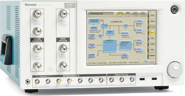
BERTScope BSX Series
Automated stress calibration
An important step in preparing for receiver testing is the calibration of the stress sources to ensure that the stress applied at the test fixture to the device under test is truly compliant with the test standard. In the past, these calibrations were often the most tedious and error-prone steps in the receiver test setup process. With the PCIe Receiver Automation Software, the calibration of the stress "recipe" is completely automated, including the calibration data. For test configurations that do not change, this step only needs to be performed once, and the stored calibration data is immediately available to be recalled. Engineers can spend less time calibrating, and more time testing.

Locating EH/EW targets

Calibration to final EH/EW targets

Automatic characterization and precise calibration of de-emphasis

Automatic characterization and precise calibration of preshoot

Automatic characterization and precise calibration of random jitter
Loopback initiation and link training
Before the receiver test can start, the device-under-test (DUT) must be put in the proper test mode, called Loopback, where the device is re-transmitting the exact same data that was received. Entering Loopback mode is challenging because of the variety of loopback negotiation sequences across the range of PCIe devices. The BERTScope PCIe software provides various techniques, including Link Training, to train and optimize the link for receiver testing.


Flexible link training and loopback control
Pattern and protocol sequencer
The BSX includes a pattern/protocol sequencer that allows users to create their own protocol-based patterns and link state traversals via stimulus-response feedback. The sequencer assists users in initiating and debugging protocol handshaking by facilitating the creation of customizable protocol sequences.
The sequencer supports up to 128 states and two levels of loop nesting. Advancing from state to state in the sequence can be accomplished by software control, external signal, or error detector match. The error detector can match up to 16 user-defined blocks, with 128 bit/s per block, and a stimulus/response trigger output allows cross-triggering of the oscilloscope.
Users can use the sequencer to create protocol sequences based on PCIe standards to facilitate loopback initiation and protocol handshaking. Those sequences can be flexibly edited (adding/removing protocol blocks, modifying symbol encoding, data scrambling, or DC balancing) to aid in debugging challenging PCIe- related protocol handshaking issues.


BER map
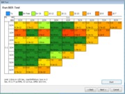
One of the key challenges setting up the link is tuning or determining the optimal RxEQ settings. The BER Map feature provides an automated way to scan the PCIe TxEQ coefficient matrix to determine the optimal TxEQ for a receiver's RxEQ settings.

Automated BER map result
Preset test
Preset testing is a critical part of the PCIe receiver test and is a single-click operation with the PCIe Automation Software. With real-time stress adjustment, quick synchronization, and BER testing ability, the BERTScope provides the ideal platform for fast jitter compliance testing. Test results are stored using the built-in database for later recall and report generation.

PCIe Preset test results
LEQ test
At higher speeds of Gen 4, dynamic link equalization becomes necessary from signal integrity viewpoint. There are two sets of link equalization test, namely for Transmitter Equalization and Receiver Equalization. BERTScope based solution provides total automation of the two tests with individual summary of results for user-analysis.
Tx Link EQ Test


Rx Link EQ Test


Remote control protocol
The test software can be operated remotely through ASCII commands sent through TCP/IP, giving engineers further flexibility in designing “beyond compliance” tests.
Debugging tools
When a device fails to meet the test requirements, the operator has the power of the full range of BERTScope debugging tools. From intuitive and fast manual stress adjustment, pattern sequencing error location analysis, and jitter decomposition, the BERTScope can help identify subtle issues that other instruments might miss.
Margin test
Margin test supports SJ Margin. Select the starting and ending SJ value and test the DUT. The BSX will be set with the appropriate starting SJ and it will test the DUT. SJ will be increased by the prescribed step size and DUT is tested again until the DUT starts failing.
Example configuration is shown in the following Margin Test configuration menu.


Ordering information
- BSXPCI3EQ
- Detector Equalization Kit for Gen3
- BSXPCI4CEM
- Automated calibration, link training, loop-back initiation and handshaking (protocol aware) test software for PCI 3.0/4.0 CEM receiver test for BSX version BERTScope
- BSXPCI4EQ
- Detector Equalization Kit for Gen4
- BSXSICOMB
- Interference combiner kit for BSX version BERTScope
- BSXPCI4BSE
- Automated calibration, link training, loop-back initiation and handshaking (protocol aware) test software for PCI 3.0/4.0 BASE receiver test using a BSX BERTScope model
- Product requirements
Tektronix BERTScope BSX125(PCIe 3.0), BSX240 (PCIe 3.0/4.0), BSX320 (PCIe 3.0/4.0) or faster with Option STR, TXEQ
Tektronix CR125A or faster clock recovery with Option PCIE8G (use as necessary)
Tektronix DPO/DSA/MSO or faster Real-Time oscilloscope with Option DJA (includes DX and SX oscilloscopes with bandwidths > 25GHz min)
RX Instrument 24Gb/s BERT BSX240 1 HW option Jitter and noise stress Option STR 1 HW option 4-tap pre-emphasis Option TXEQ 1 SW option PCIe4 RX test / Link EQ software BSXPCI4CEM 1 Kit Interference combiner kit BSXSICOMB 1 Kit Detector equalization kit BSXPCI4EQ 1 Cable SMA-SMA cable pair, 18 inches 174-6663-01 1 Cable 1-meter SMA-SMA cable pair, 1.5psec skew PMCABLE1M 2 [Optional] Cable SMA - SMP cable pair, 102mm, <1psec skew> 174-6657-01 2 Cable SMA - SMP cable pair, 1-meter 174-6659-01 1 Cable Right angle SMA-SMA cable, 0.2m 174-6664-01 1 Cable Huber Suhner SMP-SMP cable pair 12 inches 80345501 (Huber-Suhner) 2 Link EQ SW option Link EQ option for Gen3 & Gen4. Requires BSXPCI4CEM BSXPCI4LEQ 1 SW option PCIe1/2/3/4 decoder Option SR-PCIE 1 Kit Power Divider, >25GHz with 2.92mm connector PSPL5333 or similar 4 Kit DC block (Bandwidth >25GHz with 2.92 connector and capacitance 265nF (or greater) PSPL5509 or similar 4 Cable SMA-SMA cable pair, 18 inches 174-6663-01 2 Adapter 2.92mm Male to 2.92mm Male Adapter SM3242 (Fairview Microwave) 4 Cable Right angle SMA-SMA cable, 0.5m 174-6666-01 1 Cable 1-meter SMA-SMA cable pair, 1.5psec skew PMCABLE1M 4
- Host system software requirements
- Microsoft Windows 7 or later
Microsoft Explorer 6.0 SP1 or later
Microsoft Access
Accessories
Recommended test fixtures, cables, and tools
| Item | Image |
|---|---|
| Description: [PCI-SIG] PCIe 4.0 Preliminary CEM Fixture Kit PN: PCIe-CLB-X1X16, PCIe-CLB-X4X8, PCIe-CBB-MAIN, and PCIe-VAR-ISI The PCIe 4.0 CEM Beta fixtures require a VNA based characterization to determine the appropriate Insertion Loss for performing the 16 GT/s Tx Signal Quality Test and the 16 GT/s Rx Link Equalization Test. This characterization will not be performed by the PCI-SIG, but must be performed by the end user after the fixtures are delivered. Quantity: 1 | |
| Description: PCI Express Compliance Base Board (CBB) test fixture, revision 3.0. For testing PCI Express Add-in Cards, x1/x4/x8/x16. Vendor: PCI-SIG www.pcisig.com/specifications/order_form Vendor PN: CBB3 Tektronix PN: Only available from PCI-SIG Quantity: 1 |
|
| Description: PCI Express Compliance Load Board (CLB3) test fixture, revision 3.0. For testing PCI Express Platforms, x1 & x16 PCIe connectors. Vendor: PCI-SIG www.pcisig.com/specifications/order_form Vendor PN: x1/x16 CLB3 Tektronix PN: Only available from PCI-SIG Quantity: 1 |
|
| Description: PCI Express Compliance Load Board (CLB3), Revision 3.0. For testing PCI Express Platforms, x4 & x8 PCIe connectors. Vendor: PCI-SIG www.pcisig.com/specifications/order_form Vendor PN: x4/x8 CLB3 Tektronix PN: Only available from PCI-SIG Quantity: 1 |
|
| Description: Any ATX PC power supply Vendor: Tektronix recommends "PC Power & Cooling 750W Silencer MK III Series" or similar. Quantity: 1 |
|
| Description: DC Block, SMA, 26 GHz Vendor: Tektronix www.tek.com Tektronix PN: PSPL5500A, PSPL5501A, or PSPL5508 Quantity: 2 Note: This is an optional accessory and not shown in any of connection diagrams, but can be used if DC offset is encountered in any signal path. |
|
| Description: SMA-to-SMA, Straight, 500 mm, 1.5 ps phase-matched Vendor: HUBER+SUHNER www.hubersuhner.com/en Vendor PN: 84210099, T+M SF104PE/11PC35/11PCC35/500mm Tektronix PN: 174-6663-xx Quantity: 2 cable pairs |
|
| Description: SMA-to-SMA, Straight, 1000 mm, 1.5 ps phase matched Vendor: HUBER+SUHNER www.hubersuhner.com/en Vendor PN: 84210103, T+M SF104PE/11PC35/11PCC35/1000mm Tektronix PN: PMCABLE1M Quantity: 2 cable pairs |
|
| Description: SMA-to-SMA, Right-Angle, 300 mm Vendor: HUBER+SUHNER www.hubersuhner.com/en Vendor PN: 84210131, T+M MF141/16SMA/16SMA/300mm Tektronix PN: 174-6665-00 Quantity: 1 |
|
| Description: SMA-to-SMP right-angle cable pair, 102 mm, 1 ps phase-matched. Vendor: Rosenberger www.rosenberger.com/us_en Vendor PN: 71L-19K2-32K1-00102B Tektronix PN: 174-6657-xx Quantity: 3 cable pairs |  |
| Description: SMA-to-SMP right-angle cable pair, 1 m, 1 ps phase-matched Vendor: Rosenberger www.rosenberger.com/us_en Vendor PN: 71M-19K2-32S1-01000D Tektronix PN: 174-6659-xx Quantity: 1 cable pair |
|
| Description: SMA torque wrench, 8.0 in-lbs. Vendor: Fairview Microwave www.fairviewmicrowave.com/sma-fixed-torque-wrench-click-st-sma3-p.aspx Vendor PN: ST-SMA3 Tektronix PN: 003-1940-xx Quantity: 1 |
|
| Description: SMP right-angle cable extraction tool. Vendor: Fairview Microwave www.fairviewmicrowave.com/undefined-mmtl2682-p.aspx Vendor PN: MMTL2682 Tektronix PN: 003-1941-xx Quantity: 1 |
|
| Description: SMP terminator installation/extraction tool. Vendor: Fairview Microwave www.fairviewmicrowave.com/undefined-mmtl4991-p.aspx Vendor PN: MMTL4991 Tektronix PN: 003-1939-xx Quantity: 1 |
|


