
Contact us
Call us at
Available 9 AM - 5 PM CET Business Days
Download
Download Manuals, Datasheets, Software and more:
Feedback
Memory Interface Electrical Verification and Debug
DDRA and DDR-LP4 Datasheet
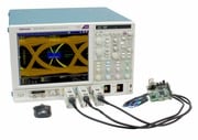
DDR Analysis is a standard specific solution tool for Tektronix Performance Digital Oscilloscopes (DPO7000C or DPO/MSO70000C/DX/SX series).The DDRA/DDR-LP4 application includes compliance measurements which enables you to achieve new levels of productivity, efficiency, and measurement reliability.
Key features
- Test coverage: The DDRA and DDR-LP4 Memory Validation Test solution are the most comprehensive DDR solutions supporting multiple memory standards including DDR4 and LPDDR4. User can configure custom data rate with programing custom limits to test and validate beyond the JEDEC specifications.
- Auto Configuration wizard: Easily set up the test configuration for performing electrical validation.
- Automating Read and Write Burst Separation: Tektronix provides unique Advanced Search and Mark (ASM) feature which helps to separate the Memory Read and Write burst automatically. ASM marks the memory Read and Write based on the phase relationship between the DQ and DQS automatically. This feature allows the user to perform JEDEC measurements over long record lengths. DDRA also offers other burst separation methods such as using command signals, Preamble Pattern Matching (LPDDR4/4X) methods.
- Multi-rank Memory Testing: The Visual Trigger Integration in DDRA/DDR-LP4 allows the user to quickly setup a Visual Trigger definition for an event of interest and use this definition to gate the measurements performed by DDRA/DDR-LP4.
- De-embedding: Quickly select and apply De-embedding filters from within DDRA/DDR-LP4 to de-embed the interposer and probe the effects to accurately represent the signal.
- Flexible Test Selection: Select the Memory specification and the Speed Grade for the targeted analysis.
- Cycle Type Identification: Navigate and timestamp all the acquired read and write cycles.
- Time to Test: User can perform multiple JEDEC measurements on multiple edges, multiple Read or Write bursts with a single acquisition. User can also provide statistical analysis with a single acquisition.
- Statistical Analysis: The DDRA application allows the user to capture long record lengths, identify Read and Write bursts automatically and perform multiple measurements on entire record length and perform statistical analysis.
- Debug: The DPOJET Jitter and Eye Diagram analysis tool is tightly integrated with the DDRA application which allows the user to switch between compliance and DPOJET debug tool with a single click. The debug environment uses the same setup, waveform, and measurement library like the DDRA. User can configure various parameters and plots for root cause analysis.
- Zoom the Debug word: The DDRA compliance software navigates the user to the waveform having failures in the current acquisition. This allows the user to look at the problematic part of the waveform when the test is running without saving the waveform.
- Reporting: Automatically generate comprehensive reports that include pass or fail results with the screen shots of all the measurements with cursors.
- Address/Command Bus Capture: The digital channels on the MSO5000 or MSO70000 Series Mixed Signal Oscilloscope can be used to precisely qualify the timing of different types of DDR bus cycles.
- Programmable Interface: Allows the development of remote client support for the memory test.
- Signal Access: Probing Memory BGA components is the most challenging job for most of the designers. Tektronix offers a wide range of Interposer for different Memory standards along with best in class probes to meet the Signal Integrity requirement. Tektronix solution partner Nexus provides Edge Interposer (Patented by Nexus), Socketed Interposer (Patented by Nexus), Direct Attached Interposer, and Interposer with Riser to meet the probing requirement for Memory validation.
Applications
Tektronix provides the most comprehensive solutions to serve the needs of the engineers designing DDR silicon for server, computer, graphics systems, mobile, and embedded systems, as well as those validating the physical layer compliance of DDR Memory Compliance Test Specification.
The Tektronix Option DDRA (DDR1/2/3/4, GDDR3/5, and LPDDR2/3) and LP4 (LPDDR4) includes compliance and debug solution for the following:
- DRAM components
- Data Buffer/RCD components
- System boards
- Embedded systems
- Automotive memory validation
- Graphics card memory validation
The Tektronix Option DDRA and LP4 applications includes the DDR compliance application and DDR compliance automation solution as well as the Tektronix DPOJET based DDR Jitter and Eye Diagram analysis tools for debug purposes in a single software package.
The Tektronix Option DDRA and Option LP4 applications are compatible with Tektronix DPO/MSO70000 series oscilloscopes that are designed to meet the challenges of the next generation memory standards. These oscilloscopes provide the industries leading vertical noise performance with the highest number of effective bits (ENOB) and flattest frequency response for oscilloscopes in their class.
DDRA compliance test
The Tektronix option DDRA and option LP4 automation for DDR Transmitter Compliance reduces the effort and accelerates the compliance testing for DDR systems and devices with several unique and innovative capabilities.
The DDRA configuration wizard provides a simple, step-by-step, and easy-to-use interface to speed up the testing process. The user can select the memory technology of interest, speed grade, measurement group (Read, Write, Clock, Address/Command Signal), and individual measurements within the group provides different methods of Burst detection.


Configuration wizard
De-embed filters
Easily de-embed the interposer and the probe effects by applying suitable de-embed filters within the DDRA/DDR-LP4 standards. The DDRA/DDR-LP4 also provides an option to apply custom filters.
De-embed filters
Comprehensive measurements
Option DDRA adds a long list of JEDEC specific measurements for different memory standards to the already existing rich tool set of generic jitter, timing, and signal quality measurements in DPOJET. The DDRA application covers Electrical Measurement, Timing Measurement, and Eye Diagram Measurement as per the JEDEC standards mentioned in the following table:
| Memory type | JEDEC specification |
|---|---|
| DDR | JESD79E |
| DDR2 | JESD79-2F |
| DDR3 | JESD79- 3F |
| DDR3L | JESD79-3-1 |
| DDR4 | JESD79-4A |
| LPDDR | JESD209B |
| LPDDR2 | JESD209-2E |
| LPDDR3 | JESD209-3B |
| LPDDR4/LPDDR4X | JESD209-4 |
| GDDR5 | JESD212 |
Automated Read and Write Burst detection
DDRA/DDR-LP4 provides different ways to detect the burst cycles that are used to make measurements:
- Built-in algorithms identify Read/Write cycles based on the DQ/DQS phase difference. This qualifies with the Chip Select for analysis targeted at specific ranks.
- MSO digital channel based Command Identification for Read/Write detection
- Defining Visual Trigger Areas to identify and gate area of interest for measurements

Burst detection
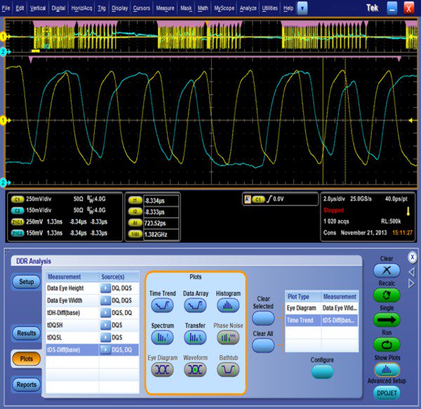
Automated Read and Write Burst detection over long record
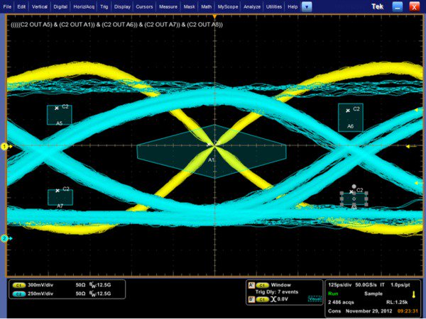
Visual trigger
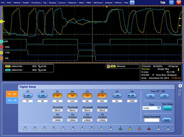
Read and Write Burst detection using MSO channel
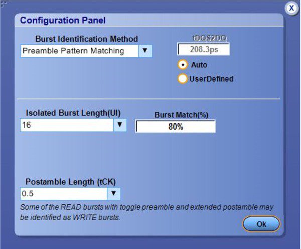
Read and Write Burst detection using Preamble matching
Results and reporting with waveform
The measurement configurations and JEDEC pass/fail limits are automatically applied for the selected measurements based on the memory specification and the selected speed grade. The results report includes DDR Measurements Statistical Data, Measurement Plots, and the screenshot of the waveforms with cursors.
Hyperlinks within the report allow navigation between the different sections.
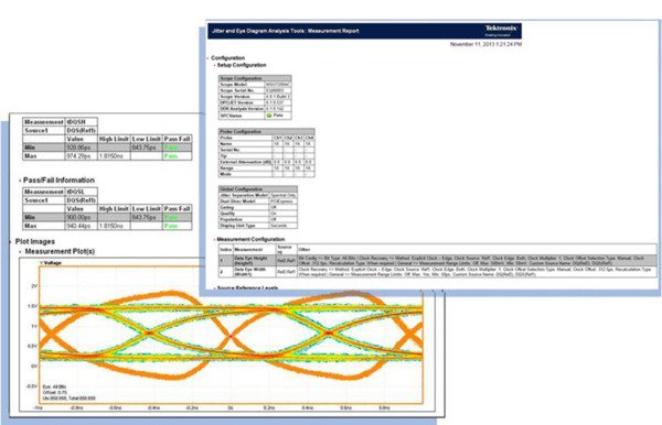
DDRA/DDR-LP4 reports

Measurement results
Statistical Analysis
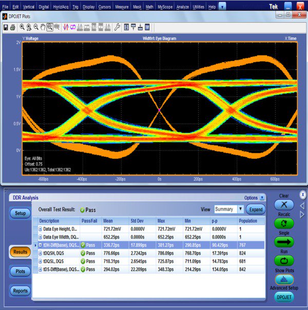
The Tektronix DDRA solution can capture long records, automatically separate Read and Write bursts based on selected measurements and perform measurements over multiple Read or Write bursts. User can run multiple Runs by programming a number of populations or continuous Run to perform statistical analysis. The user can stop on a limit failure, to debug.
Verification versus debug
The DDRA/DDR-LP4 provides a comprehensive set of JEDEC measurements for different memory standards. In addition to this, it also provides access to the DPOJET advanced Jitter and Timing analysis engine that allows flexibility to reconfigure the existing measurements or to perform new measurements which are not defined by the JEDEC specification using new user specified test limits. It also features logging, filters, histograms, and time trends that are available in DPOJET. The user can also switch between debug mode and the compliance mode.
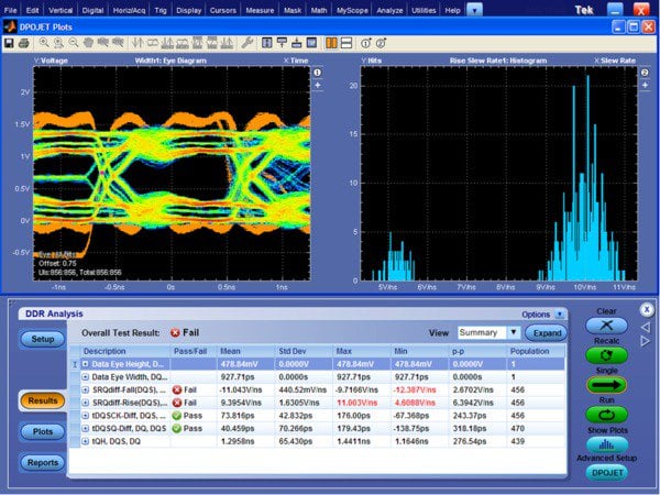
Memory interface analysis in DPOJET
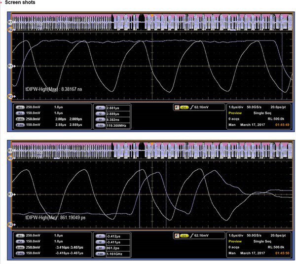
The DDRA application allows the user to navigate to waveforms where Min measurements were measured; this allows the user to debug the Min measured value.
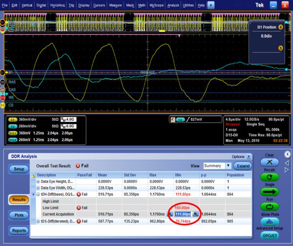
Oscilloscope triggering and waveform identification
The Tektronix Pinpoint®trigger system provides the most comprehensive high performance trigger system in the industry. The Pinpoint trigger system encompasses threshold and timing related triggers, Dual A and B Event Triggering, Logic Qualification, Window Triggering, and Reset Triggering.
The Advanced Search and Mark feature on the Tektronix MSO/DPO5000, DPO7000, and MSO/DPO70000 Series Oscilloscopes finds unique events in the waveforms. It scans acquired waveform data for multiple occurrences of an event and marks each occurrence.
The Search and Mark feature has a close relationship with the Pinpoint trigger system since they both can be used to discriminate signal characteristics. Search and Mark includes signal-shape discrimination features of the Pinpoint trigger system and extends them across live channels, stored data, and math waveforms.
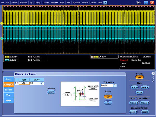
Pinpoint triggering
Visual Trigger makes the identification of the desired waveform events quick and easy by scanning all the acquired analog waveforms and comparing them with the geometric shapes on the display. By discarding the acquired waveforms which do not meet the graphical definition, Visual Triggering extends the oscilloscope’s trigger capabilities beyond the traditional hardware trigger system.

Graphical triggering using Visual Trigger
These capabilities of the oscilloscope are very useful during debug and are also extensively used by DDRA/DDR-LP4 during the analysis.
Additional capabilities using a Performance Mixed Signal Oscilloscope
The Mixed Signal Oscilloscope allows probing of more signals on the memory bus and on the trigger and to view specific bus events. With a Tektronix MSO5000 or MSO70000 Series Oscilloscope, up to 16 digital channels can be used to view logic states of command and address signals such as RAS, CAS, WE, CE, or CS.
On the MSO70000, signal integrity of these 16 inputs can be analyzed using the iCapture™ multiplexing feature, which allows any of the digital input signals to be internally routed to one of the four analog channels of the oscilloscope. The measurements involving command-bus cycle timing can also be analyzed using the bus-decode features of the MSO and DDRA/DDR-LP4 software.
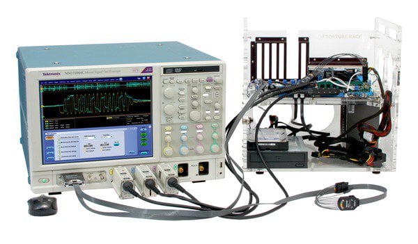
MSO70000 Series Oscilloscope probing command signals
Probing
In order to perform analysis on the memory bus, accessing the signal plays a very important role. The JEDEC specification requires the signals to be probed at the BGA balls of the memory device.
Tektronix, in partnership with Nexus Technology, is offering probing options such as BGA interposers that support different memory devices in a variety of form factors. The interposer includes an embedded tip resister placed very close to the BGA pad.
Introduction of an interposer and the oscilloscope probe may change the characteristics of the signal. Apply De-embedding filters to remove the effect of the interposer and a probe in the signal path to get an accurate representation of the signal at the probe point.
| Technology | Package / Form factor |
|---|---|
| DDR5 | Coming soon 1 |
| DDR4 | Edge Probe – 78 Ball / 96 Ball / 144 Ball Socketed – 78 Ball / 96 Ball DIMM and SODIMM interposer for MSO |
| DDR3 | Socketed – 78 Ball / 96 Ball Edge Probe – 78 Ball / 96 Ball Solder-down – 78 Ball / 96 Ball DIMM and SODIMM Interposer for MSO |
| DDR2 | Socketed – 60 Ball / 84 Ball Solder-down – 60 Ball / 84 Ball |
| LPDDR4 / LPDDR4X | Socketed – 200 Ball / 272 Ball Edge Probe – 272 Ball / 366 Ball |
| LPDDR3 | Socketed – 216 Ball / 211 Ball Solder-down – 178 Ball / 211 Ball |
| LPDDR2 | Socketed – 136 Ball / 168 Ball / 216 Ball / 240 Ball |
| LPDDR | Socketed – 60 Ball |
| GDDR5 | Socketed – 170 Ball Solder-down – 170 Ball |
Edge Probe
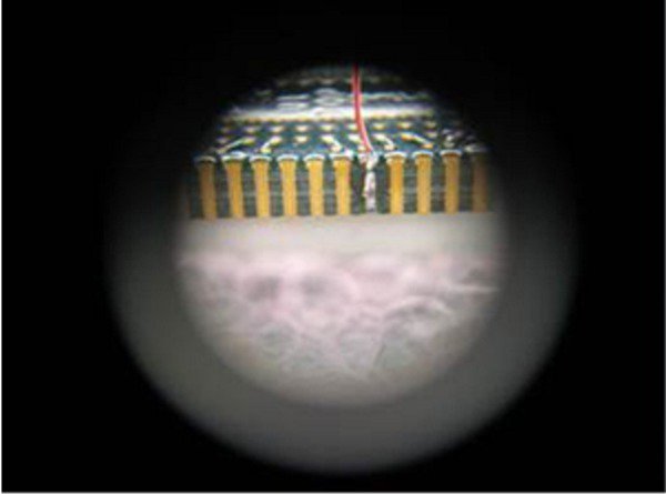
The Nexus Technology's Patented EdgeProbe™ design is available with DDR3, DDR4, LPDDR2, LPDDR3, LPDDR4, Flash, and NAND products. This technology allows for analog acquisition of Command, Address, Read, and Write Data. The Nexus Technology's Patent Peding EdgeProbe design removes mechanical clearance issues as the interposers are targeted to be the size of the memory components. Embedded resistors within the interposers place the oscilloscope probe tip resistor extremely close to the BGA pad, providing an integrated oscilloscope probe on all the signals.
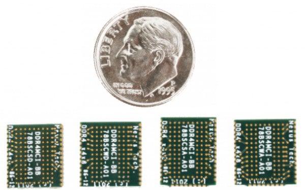
DDR4 Edge Probe Component Interposers (sizing relative to U.S. coin)
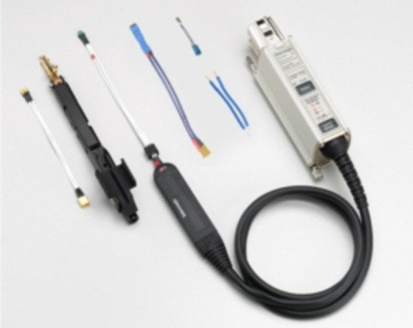
P7500 Series Trimode™ Probe system with accessories
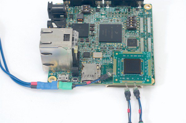
LPDDR2 component package on package interposer
1Fore more details, please contact Tektronix.
Logic debug and protocol analysis
When full protocol analysis or probing of the entire memory bus is required, a logic analyzer can provide this capability. The TLA7000 Series logic analyzers can also be linked with the Tektronix oscilloscopes to provide an integrated test setup, using iCapture tools.
This eliminates the need for double probing and allows full analog capture of any signals probed by the logic analyzer. In addition, the iView™ display allows to transfer of the oscilloscope data to a logic analyzer display, so that the data from both the instruments are analyzed and time-aligned on the display screen. Various types of probing solutions are available to support different form factors.
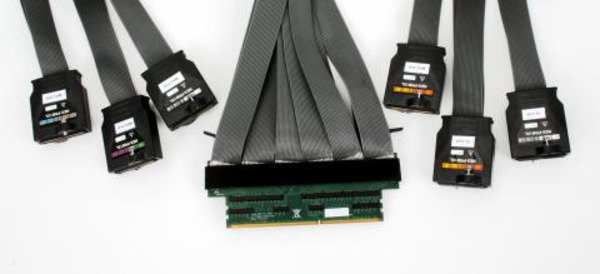
TLA Logic Analyzer and Probes for multichannel signal capture
Oscilloscope bandwidth considerations for memory analysis
| Memory technology | DDR2 | DDR2 | DDR3 | DDR3 | DDR3L | LPDDR3 | LPDDR4 | LPDDR4X | DDR4 | DDR5 |
|---|---|---|---|---|---|---|---|---|---|---|
| Speed | to 400MT/s | to 800MT/s | to 1600MT/s | to 2400MT/s | to 1600MT/s | to 1600MT/s | to 4266MT/s | to 4266MT/s | to 3200MT/s | Coming soon 1 |
| Max slew rate | 5 | 5 | 10 | 12 | 12 | 8 | 18 | 18 | 18 | |
| Typical V swing | 1.25 | 1.25 | 1 | 1 | 0.9 | 0.6 | 0.3 | 0.25 | 0.8 | |
| 20-80 risetime (ps) | 150 | 150 | 60 | 50 | 45 | 45 | 27 | 27 | 27 | |
| Equivalent Edge BW | 2.7 | 2.7 | 6.7 | 8.0 | 8.9 | 8.9 | 15.0 | 15.0 | 15.0 | |
| Recommended Oscilloscope BW (max performance) 2 | 3.5 | 4.0 | 12.5 | 12.5 | 12.5 | 12.5 | 16 | 16 | 16 | |
| Recommended Oscilloscope BW (typical performance) 3 | 2.5 | 3.5 | 8.0 | 12.5 | 12.5 | 12.5 | 12.5 | 12.5 | 12.5 |
1Fore more details, please contact Tektronix.
2High accuracy on faster slew rates.
3Slew rates are about 80% of the max specification. DDR3L, DDR4, and LPDDR3 is supported on only MSO/DPO70000C/DX/SX.
Ordering information
Models
- DDRA
- DDR Memory Bus Electrical Validation and Analysis Oscilloscope Software
- DDR-LP41
- LPDDR4 Memory Bus Electrical Validation and Analysis Oscilloscope Software
1DDR-LP4 is not available on DPO/MSO5000 and 7000 Series Oscilloscopes for LPDDR4/4X.
To order a new DPO/MSO5000, DPO7000, and DPO/MSO70000 Series:
- Option DDRA
- Preinstall on a new DPO5000 1, MSO50001, DPO70001, DPO700001, or MSO700001 Series Oscilloscope
- DPOFL-DDRA
- DDR Memory Bus Electrical Validation and Analysis Oscilloscope Software – Floating License
- Option DDR-LP41
- Preinstall on a new DPO700001 or MSO700001 Series Oscilloscope
- DPOFL-DDR-LP41
- LPDDR41 Memory Bus Electrical Validation and Analysis Oscilloscope Software – Floating License
1DDR3L, DDR4, LPDDR3, and LPDDR4/LPDDR4X are supported on only MSO/DPO70000C/DX/SX models.
To upgrade an existing DPO/MSO5000, DPO7000, and DPO/MSO70000 Series:
- DPO-UP DDRA
- Upgrade to Option DDRA1 (requires Options ASM and DJA)
- DPO-UP DDR-LP41
- Upgrade to Option DDR-LP41 (requires Option ASM, DJA and DDRA)
- DPO-UP DJAE
- Upgrade MSO/DPO5000 Series with DPOJET Jitter and Eye Diagram Analysis (Option DJA)
- DPO-UP DJAM
- Upgrade DPO7000 with DPOJET Jitter and Eye Diagram Analysis (Option DJA)
- DPO-UP DJAH
- Upgrade DPO70404 - DPO70804 or MSO70404 - MSO70804 with DPOJET Jitter and Eye Diagram Analysis (Option DJA)
- DPO-UP DJAU
- Upgrade DPO71254 - DPO73304 or MSO71254 - MSO72004 with DPOJET Jitter and Eye Diagram Analysis (Option DJA)
- DPO-UP DJUP
- DJA DPOJET software for oscilloscopes with both TDSJIT3 and TDSRTE licenses
To order floating licenses on existing DPO/MSO5000, DPO7000, and DPO/MSO70000 Series:
- DPOFL-DDRA
- DDRA1 Package – Floating License
- DPOFL-DDR-LP41
- LPDDR41 Memory Bus Electrical Validation and Analysis Oscilloscope Software – Floating License
- DPOFL-DJA
- DPOJET Jitter and Eye Diagram Analysis – Floating License
Recommended accessories
- P7500 Series
- TriMode™ Differential Probe
- 020-2955-xx
- Micro-coax Tips (TriMode) for P7500 Series Probes
- 020-3022-xx
- Micro-coax Tips (TriMode) for P7500 Series Probes 1
- 020-2954-xx
- Socket Cable for P7500 Series Probes
- 020-3131-xx
- Long Reach Solder Tip with 75 Ω tip resistor for P7500 Series Probes
- 020-3135-xx
- Long Reach Solder Tip with 0 Ω tip resistor for P7500 Series Probes
- P7300 Series
- Z-Active™ Differential Probe (P7313, P7340A, P7360A, or P7380A)
- 020-2600-xx
- Short Flex, Small Resistor Tip-Clip Assembly for P7300 Series Probes
- 020-2602-xx
- Medium Flex, Small Resistor Tip-Clip Assembly for P7300 Series Probes
- 020-2604-xx
- Long Flex, Small Resistor Tip-Clip Assembly for P7300 Series Probes
- 006-3415-xx
- Antistatic Wrist Strap for P7300 Series Probes
- P6780
- Differential Logic Probe for MSO70000 Series Oscilloscopes
- TDP3500
- Differential Probe for MSO/DPO5000 and DPO7000 Series Oscilloscopes
1For use with BGA Interposers only.
BGA interposers by memory standard
- DDR2
- x4, x8, x16 socketed and solder-down interposers
- DDR3
- x4, x8,16 Edge, socketed, solder-down and direct attach interposers
- DDR4
- x4, x8,16 Edge, socketed, solder-down and direct attach interposers
- LPDDR2
- BGA, PoP and Edge interposers
- LPDDR3
- BGA , PoP and Edge interposers
- LPDDR4/LPDDR4X
- PoP and Edge Interposer
- GDDR5
- Solder-Down and socketed interposers
Please contact Tektronix for more information on Interposer offerings.


