
Contact us
Call us at
Available 6:00 AM – 5:00 PM (PST) Business Days
Download
Download Manuals, Datasheets, Software and more:
Feedback
Digital Storage Oscilloscopes
TBS1000B Series Datasheet
The products on this datasheet are no longer being sold by Tektronix.
View Tektronix Encore for reconditioned test equipment.
Check support and warranty status for these products.
More Information
- TBS1000C 2 Channel Digital Storage Oscilloscope
- Explore more Software models
Read Online:
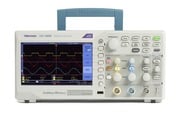
The TBS1000B Digital Storage Oscilloscope Series provides you with affordable performance in a compact design. Packed with standard features - including USB connectivity, 34 automated measurements, limit testing, data logging, frequency counter, TrendPlot™ and a context-sensitive help menu - the TBS1000B Series oscilloscopes helps you get more done, in less time.
Key performance specifications
200 MHz, 150 MHz, 100 MHz, and 70 MHz bandwidth models
- 2-channel models
Up to 2 GS/s sample rate on all channels
- 2.5k point record length on all channels
- Advanced triggers including pulse and line-selectable video triggers
Key features
7 inch WVGA (800X480) Active TFT Color Display
34 automated measurements
- Dual window FFT, simultaneously monitors both the time and frequency domains
Built-in waveform limit and TrendPlot™ testing
- Dual channel frequency counter
- Zoom Function
- Automated, extended data logging feature
- Autoset and auto-ranging functions
- Built-in context-sensitive help
- Multiple-language user interface
- Small footprint and lightweight - Only 4.9 in. (124 mm) deep and 4.4 lb. (2 kg)
Connectivity
- USB 2.0 host port on the front panel for quick and easy data storage
- USB 2.0 device port on rear panel for easy connection to a PC
Seeing signal details
To properly analyze signals you need to make sure that you can see them in enough detail. The TBS1000B comes standard with a 7-inch high resolution TFT display for a clear view of all of your signals and critical on screen information. The instrument is further enhanced by a user interface inspired by the award winning Tektronix MSO/DPO series of instruments. The interface is easy to use, provides quick access to all of the oscilloscope functions and includes a high resolution "Pan & Zoom" feature enabling you to see even more signal details of up to 10 times normal resolution.

The zoom function shows details in an event of up to 10X the normal view.
Digital precision for accurate measurements
With up to 200 MHz bandwidth, 2 GS/s maximum sample rate and 3% vertical measurement accuracy the TBS1000B allows you to see the details of your signals. With the Tektronix proprietary sampling technology there are no compromises, you will get the stated real-time sampling rate on all channels, all the time with at least of 10X oversampling. The sampling performance is not reduced when changing horizontal settings or when using multiple channels, enabling you to see the true characteristics of your signals.
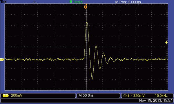
See all the details other oscilloscopes might miss with Tektronix proprietary digital real- time sampling.
Critical tools for troubleshooting your device
The TBS1000B oscilloscope comes standard with a variety of advanced triggers used to debug today's complex circuitry. Flexible options for utilizing rising or falling edges, pulse widths and video trigger set-ups enable users to quickly isolate their signals of interest.

The pulse trigger function can easily capture critical events.
Once signals are captured, the TBS1000B offers advanced math and measurement capabilities making it easy to evaluate signal quality . Users can add, subtract and multiply waveforms or use any one of 34 automated measurements to quickly and reliably calculate important signal characteristics such as frequency, rise time or overshoot.
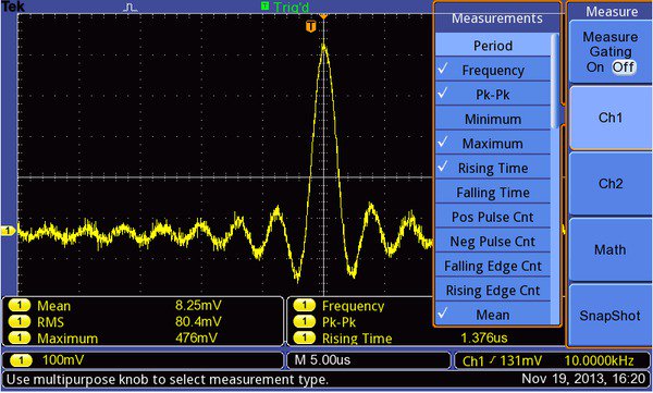
Quickly analyze signals with the standard 34 automated measurements.
A dedicated front panel button provides quick access to the FFT function that is capable of showing both frequency and time domain waveforms simultaneously, which provides a convenient way to see the relationship between signals and the FFT results.
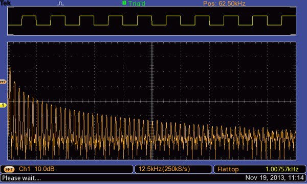
Quickly perform an FFT with a dedicated front panel button.
For accurate frequency measurements the TBS1000B also comes with built-in dual channel frequency counters. Independent control of each counter's trigger level provides an easy way to monitor two different signal frequencies simultaneously.
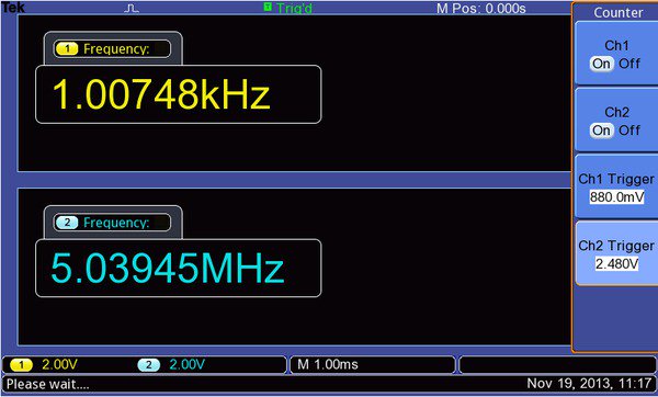
Dual channel - 6 digit frequency counters come standard with all TBS1000 models.
Extensive monitoring and analysis tools
Intermittent faults can be hard to evaluate, simply because they do not repeat often making them difficult to capture. The TrendPlot™ function helps find those faults by plotting measurement values over long periods of time. Select the measurement to capture on either or both channels and then set-up the oscilloscope to continuously monitor those measurements, plot the data on the display and simultaneously save the information to a USB thumb drive. Depending on the oscilloscope setting, you'll be able to capture data for minutes, hours or even days; the only limitation is the size of the thumb drive.
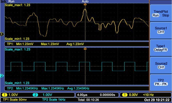
To find intermittent faults the TrendPlot ™ function can monitor measurements for long periods of time.
Often, only Pass/Fail data is needed to determine if a signal is good. This can be accomplished easily with the TBS1000B Limit Test feature. The oscilloscope can be set-up to automatically monitor a source signals and output Pass or Fail results by evaluating whether the acquired waveform falls within predefined boundaries. The TBS1000B Limit Test feature allows users to create templates based on one or two independent reference waveforms, providing more flexibility when creating masks for complex signals. If a failure is detected, a series of specific actions can be triggered which include; stopping waveform acquisition, halting Limit Test functions, saving a screen image of the failed waveform, or any combination of the above.

The Limit Test feature provides a quick Pass/Fail comparison between any triggered input signal and a user- defined template.
Flexible data transfer
The USB host port on the front panel enables you to save your instrument settings, screenshots, and waveform data onto a USB memory device. This port also supports the built-in Data Logging feature which enables you to set up the oscilloscope to save user- specified triggered waveforms to a USB device for up to 24 hours. You can also select the "Infinite" option for continuous waveform monitoring. In the infinite mode you can save your triggered waveforms to an external USB memory device without a duration limitation until the memory device is full. The oscilloscope will then guide you to insert another USB memory device to continue saving waveforms.
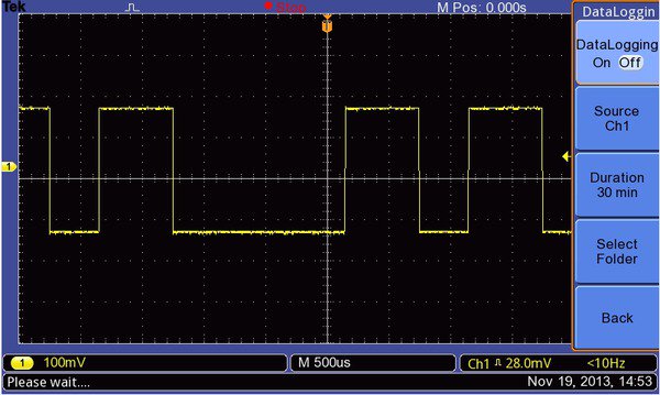
Data logging enables automatic saving of triggered waveforms.
Designed to make your work easy
The TBS1000B series oscilloscopes are designed with the ease of use and familiar operation you have come to expect from Tektronix.
Intuitive operation
The intuitive user interface with dedicated per-channel vertical controls, auto-setup, and auto-ranging makes these instruments easy to use, reducing learning time and increasing efficiency.
Help when you need it, where you need it
The built-in Help menu provides you with important information about your oscilloscope's features and functions. Help is provided in the same languages as the user interface.
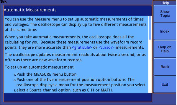
The context-sensitive help system provides important information specific to the task you are working on.
Performance you can count on
In addition to industry-leading service and support, every TBS1000B series oscilloscope comes backed with a 5-year warranty as standard.
Specifications
All specifications are guaranteed unless noted otherwise. All specifications apply to all models unless noted otherwise.
Model overview
| TBS1072B | TBS1102B | TBS1152B | TBS1202B | |
|---|---|---|---|---|
| Bandwidth | 70 MHz | 100 MHz | 150 MHz | 200 MHz |
| Channels | 2 | 2 | 2 | 2 |
| Sample rate on each channel | 1.0 GS/s | 2 .0 GS/s | 2 .0 GS/s | 2 .0 GS/s |
| Record length | 2.5k points at all-time bases | |||
Vertical system – Analog channels
- Vertical resolution
- 8 bits
- Input sensitivity range
- 2 mV to 5 V/div on all models with calibrated fine adjustment
- DC gain accuracy
- ±3%, from 10 mV/div to 5 V/div
- Maximum input voltage
- 300 VRMS CAT II; derated at 20 dB/decade above 100 kHz to 13 Vp-p AC at 3 MHz and above
- Offset range
2 mV to 200 mV/div: ±1.8 V
>200 mV to 5 V/div: ±45 V
- Bandwidth limit
- 20 MHz
- Input coupling
- AC, DC, GND
- Input impedance
- 1 MΩ in parallel with 20 pF
- Vertical zoom
- Vertically expand or compress a live or stopped waveform
Horizontal system — Analog channels
- Time base range
- 30 MHz model1
- 10 ns to 50 s/div
- 50 MHz and 70 MHz models
- 5 ns to 50 s/div
- 100MHz, 150MHz and 200MHz models
- 2.5 ns to 50 s/div
- Time base accuracy
- 50 ppm
- Horizontal zoom
- Horizontally expand or compress a live or stopped waveform
Input/Output ports
- USB interface
- USB host port on front panel supports USB flash drives.
- GPIB interface
- Optional
Data storage
- Nonvolatile storage
- Reference waveform display
- 2.5K point reference waveforms
- Waveform storage without USB flash drive
- 2.5K point
- Maximum USB flash drive size
- 64 GB
- Waveform storage with USB flash drive
- 96 or more reference waveforms per 8 MB
- Setups without USB flash drive
- 10 front-panel setups
- Setups with USB flash drive
- 4000 or more front-panel setups per 8 MB
- Screen images with USB flash drive
- 128 or more screen images per 8 MB (the number of images depends on file format selected)
- Save All with USB flash drive
- 12 or more Save All operations per 8 MB
A single Save All operation creates 3 to 9 files (setup, image, plus one file for each displayed waveform)
Acquisition system
- Acquisition modes
- Peak Detect
- High-frequency and random glitch capture. Captures glitches as narrow as 12 ns (typical) at all time base settings from 5 μs/div to 50 s/div
- Sample
- Sample data only
- Average
- Waveform averaged, selectable: 4, 16, 64, 128
- Single Sequence
- Use the Single Sequence button to capture a single triggered acquisition sequence
- Roll
- At acquisition time base settings of >100 ms/div
Trigger system
- External trigger input
- Included on all models
- Trigger modes
- Auto, Normal, Single Sequence
- Trigger types
- Edge (Rising/Falling)
- Conventional level-driven trigger. Positive or negative slope on any channel. Coupling selections: AC, DC, Noise Reject, HF Reject, LF Reject
- Video
- Trigger on all lines or individual lines, odd/even or all fields from composite video, or broadcast standards (NTSC, PAL, SECAM)
- Pulse Width (or Glitch)
- Trigger on a pulse width less than, greater than, equal to, or not equal to, a selectable time limit ranging from 33 ns to 10 s
- Trigger source
- Two channel models: CH1, CH2, Ext, Ext/5, AC Line
- Trigger view
- Displays trigger signal while Trigger View button is depressed.
- Trigger signal frequency readout
- Provides a frequency readout of the trigger source.
Waveform measurements
- Cursors
- Types
- Amplitude, Time
- Measurements
- ΔT, 1/ΔT, ΔV
- Automatic measurements
Period, Frequency, Pos Width, Neg Width, Rise Time, Fall Time, Maximum , Minimum , Peak-Peak, Mean, RMS, Cycle RMS, Cursor RMS, Phase, Pos Pulse Cnt, Neg Pulse Cnt, Rise Edge Cn, Fall Edge Cn, Pos Duty, Neg Duty, Amplitude, Cycle Mean, Cursor Mean, Burst Width, Pos Overshoot, Neg Overshoot, Area, Cycle Area, High, Low, Delay RR, Delay RF, Delay FR, Delay FF
Waveform math
- Arithmetic
- Add, Subtract, Multiply
- Math functions
- FFT
- FFT
- Windows: Hanning, Flat Top, Rectangular
- Sources
- Two channel models: CH1 - CH2, CH2 - CH1, CH1 + CH2, CH1 × CH2
Autoset
- Autoset menu
- Single-button, automatic setup of all channels for vertical, horizontal, and trigger systems, with undo Autoset
- Square wave
- Single Cycle, Multicycle, Rising or Falling Edge
- Sine wave
- Single Cycle, Multicycle, FFT Spectrum
- Video (NTSC, PAL, SECAM)
- Field: All, Odd, or Even
Autorange
- Automatically adjust vertical and/or horizontal oscilloscope settings when probe is moved from point to point, or when the signal exhibits large changes.
Frequency counter
- Resolution
- 6 digits
- Accuracy (typical)
- + 51 parts per million including all frequency reference errors and +1 count errors
- Frequency range
- AC coupled, 10 Hz minimum to rated bandwidth
- Frequency counter signal source
Pulse width or edge selected trigger source
Frequency counter measures selected trigger source at all times in pulse width and edge mode, including when the oscilloscope acquisition is halted due to changes in run status, or acquisition of a single shot event has completed.
The frequency counter does not measure pulses that do not qualify as legitimate trigger events.
Pulse Width mode: Counts pulses of enough magnitude inside the 250 ms measurement window that qualify as triggerable events (e.g. all narrow pulses in a PWM pulse train if set to "<" mode and the limit is set to a relatively small number).
Edge Trigger mode: Counts all pulses of enough magnitude.
- Channels
- 2 channel
Display system
- Interpolation
- Sin (x)/x
- Waveform styles
- Dots, vectors
- Persistence
- Off, 1 s, 2 s, 5 s, infinite
- Format
- YT and XY
Power source
- Power source voltage
- 100 to 240 V ±10%
- Power source frequency
- 100 V to 240 V
- 50 Hz to 60 Hz
- 115 V
- 400 Hz ±10%
- Power consumption
- 30 W maximum
Physical characteristics
- Dimensions
mm in. Height 158.0 6.22 Width 326.3 12.85 Depth 124.2 4.89
- Shipping dimensions
mm in. Height 266.7 10.5 Width 476.2 18.75 Depth 228.6 9.0
- Weight
kg lb. Instrument only 2.0 4.3 ...with accessories 2.2 4.9
- RM2000B rackmount
mm in Width 482.6 19.0 Height 177.8 7.0 Depth 108.0 4.25
Environmental
- Temperature
- Operating
- 0 to +50 ºC
- Nonoperating
- –40 to +71 ºC
- Humidity
- Operating and nonoperating
Up to 85% RH at or below +40 ºC
Up to 45% RH up to +50 ºC
- Altitude
- Operating and nonoperating
- Up to 3,000 m (9,843 ft.)
- Regulatory
- Electromagnetic compatibility
- Meets Directive 2004/108/EC, EN 61326-2-1 Class A; Australian EMC Framework
- Safety
- UL61010-1:2004, CSA22.2 No. 61010-1:2004, EN61010-1:2001, IEC61010-1:2001
Ordering information
Models
- TBS1072B
70 MHz, 2 Ch, 1 GS/s, TFT DSO
- TBS1102B
100 MHz, 2 Ch, 2 GS/s, TFT DSO
- TBS1152B
150 MHz, 2 Ch, 2 GS/s, TFT DSO
- TBS1202B
200 MHz, 2 Ch, 2 GS/s, TFT DSO
Language options
- Opt. L1
- French overlay
- Opt. L2
- Italian overlay
- Opt. L3
- German overlay
- Opt. L4
- Spanish overlay
- Opt. L5
- Japanese overlay
- Opt. L6
- Portuguese overlay
- Opt. L7
- Simplified Chinese overlay
- Opt. L8
- Traditional Chinese overlay
- Opt. L9
- Korean overlay
- Opt. L10
- Russian overlay
Power plug options
- Opt. A0
- North America power plug (115 V, 60 Hz)
- Opt. A1
- Universal Euro power plug (220 V, 50 Hz)
- Opt. A2
- United Kingdom power plug (240 V, 50 Hz)
- Opt. A3
- Australia power plug (240 V, 50 Hz)
- Opt. A5
- Switzerland power plug (220 V, 50 Hz)
- Opt. A6
- Japan power plug (100 V, 50/60 Hz)
- Opt. A10
- China power plug (50 Hz)
- Opt. A11
- India power plug (50 Hz)
- Opt. A12
- Brazil power plug (60 Hz)
- Opt. A99
- No power cord
Service options
- Opt. D1
- Calibration Data Report
Probes and accessories are not covered by the oscilloscope warranty and Service Offerings. Refer to the datasheet of each probe and accessory model for its unique warranty and calibration terms.
Probe option
- TBS1XX2B P2220
- Replaces standard probes with P2220 probes (200 MHz passive voltage probes with 1x/ 10x attenuation)
Standard accessories
| Accessory | Description |
|---|---|
| Passive probes, one per channel | TPP0101: 100 MHz passive probe for: TBS1072B, TBS1102B |
| TPP0201: 200 MHz passive probe for: TBS1152B, TBS1202B | |
| Power cord | (Please specify plug option) |
| NIM/NIST | Traceable certificate of calibration |
| Printed documentation | Installation and safety manual |
| (English, Japanese, and Simplified Chinese) | |
| CD with customer documentation | Customer documentation including detailed user manuals (English, French, German, Italian, Japanese, Korean, Portuguese, Russian, Simplified Chinese, Spanish, Traditional Chinese) |
| 5-year warranty | Covers labor and parts for defects in materials and workmanship for 5 years, excluding probes and accessories (probes and accessories are not covered by the oscilloscope warranty and service offerings. refer to the data sheet of each probe and accessory model for its unique warranty and calibration terms) |
Recommended accessories
| Accessory | Description |
|---|---|
| TEK-USB-488 | GPIB-to-USB converter |
| AC2100 | Soft carrying case for instrument |
| HCTEK4321 | Hard plastic carrying case for instrument (requires AC2100) |
| RM2000B | Rackmount kit |
| 077-0444-xx | Programmer manual – English only |
| 077-0772-xx | Service manual – English only |
| 174-4401-xx | USB host to device cable, 3 ft. long |
Recommended probes
| Probe | Description |
|---|---|
| TPP0051 | 10X passive probe, 50 MHz bandwidth |
| TPP0101 | 10X passive probe, 100 MHz bandwidth |
| TPP0201 | 10X passive probe, 200 MHz bandwidth |
| P2220 | 1X/10X passive probe, 200 MHz bandwidth |
| P6101B | 1X passive probe (15 MHz, 300 V RMS CAT II rating) |
| P6015A | 1000X high-voltage passive probe (75 MHz) |
| P5100A | 100X high-voltage passive probe (500 MHz) |
| P5200A | 50 MHz, 50X/500X high-voltage differential probe |
| P6021A | 15 A, 60 MHz AC current probe |
| P6022 | 6 A, 120 MHz AC current probe |
| A621 | 2000 A, 5 to 50 kHz AC current probe |
| A622 | 100 A, 100 kHz AC/DC current probe/BNC |
| TCP303/TCPA300 | 150 A, 15 MHz AC/DC current probe/amplifier |
| TCP305A/TCPA300 | 50 A, 50 MHz AC/DC current probe/amplifier |
| TCP312A/TCPA300 | 30 A, 100 MHz AC/DC current probe/amplifier |
| TCP404XL/TCPA400 | 500 A, 2 MHz AC/DC current probe/amplifier |


