Contact us
Call
Call us at
Available 6:00 AM – 5:00 PM (PST) Business Days
Download
Download Manuals, Datasheets, Software and more:
Feedback
PSPL5546 7 GHz Bias Tee
PSPL5546 Datasheet
The products on this datasheet are no longer being sold by Tektronix.
View Tektronix Encore for reconditioned test equipment.
Check support and warranty status for these products.
PSPL5546 Datasheet
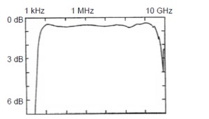
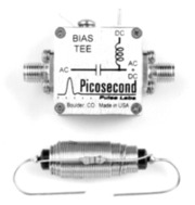
The PSPL5546 is a broadband, coaxial bias insertion tee and DC blocking capacitor. It was designed to have a very low cutoff frequency of only 3.5 kHz. It passes fast rise pulses with a minimum of waveform distortion. Its rise time is 45 ps. The frequency response is very flat, and the -3 dB bandwidth extends from 3.5 kHz to 7 GHz. The PSPL5546 is supplied with a 1 mH choke and terminal strip for connection to the DC bias.
Key performance specifications
- 3.5 kHz to 7 GHz
- 45 ps rise time
- 50 V, 500 mA
Typical performance

1 db/div log plot to 10 GHz Insertion Loss
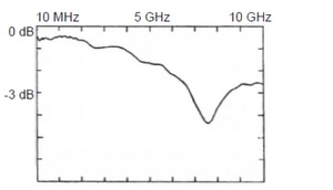
1 db/div log plot to 10 GHz Insertion Loss
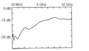
5 dB/div log plot to 10 GHz Return Los
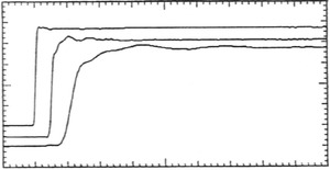
Top to bottom: 1 ns/div, 200 ps/div, and 50 ps/div. Response to 20 ps rise time input step
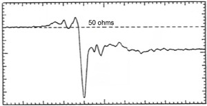
2.5% rho/div and 200 ps/div. 35 ps rise time input step
Specifications
| Parameter | Symbol | Units | Minimum | Typical | Maximum | Comments |
|---|---|---|---|---|---|---|
| Impedance | Z | ohms | 50 | |||
| Upper 3 dB frequency | fc,h | GHz | 4 | 7 | ||
| Lower 3 dB frequency | fc,l | kHz | 3.5 | |||
| Rise time | tr | ps | 45 | 75 | 10 – 90% | |
| Insertion loss | S21 | dB | 0.5 | |||
| Input (AC) Return Loss |
S11 | dB | 23 | f = 100 MHz | ||
| Refl. Coefficient (35 ps TDR) | Γ | % | -5 | t > 200 ps | ||
| DC voltage | V | Volts | 50 | |||
| DC current | I | mA | 500 | |||
| Capacitance | C | μF | 0.9 | - 50%, + 80% | ||
| Inductance | L | mH | 1.34 | +/- 30% 1 | ||
| Resistance | R | ohms | 1.5 | |||
| RF power | P | W | 2 | Average power | ||
| Isolation | S13 | dB | 30 | |||
| DC path bandwidth | fc,DC | kHz | 4.5 | |||
| RF Connectors | SMA jacks (f) | |||||
| DC Connector | Solder pin | |||||
| Warranty | One Year | |||||
1 A 1 mH choke is supplied with the bias tee. It is to be wired in series directly to the DC in solder terminal on the coax module. This is a high impedance point. Avoid using long wire, especially coax, for this connection. Do not locate the choke close to ground. Excessive stray capacitance will cause a resonance that will appear as a dip in the insertion loss between 1 and 10 MHz.
Mechanical dimensions
Ordering information
Models
- PSPL5546
- BIAS TEE, 7 GHz, 50 V


