Contact us
Call us at
Available 9 AM - 5 PM SST Business Days
Download
Download Manuals, Datasheets, Software and more:
Feedback
80SJARB and 80SJNB Jitter, Noise, and BER Analysis
Software for DSA8300 Sampling Oscilloscopes- Datasheet
The products on this datasheet are no longer being sold by Tektronix.
View Tektronix Encore for reconditioned test equipment.
Check support and warranty status for these products.
High-speed serial data link measurements and analysis are supported with three software solutions. 80SJARB is a basic jitter measurement tool capable of measuring jitter on any waveform – arbitrary or very long patterns. 80SJNB Essentials (80SJNB) offers complete analysis of jitter, noise, and BER, with decomposition of components for a clear understanding of a signal’s problems and margins. 80SJNB Advanced (80SJNB02) adds Serial Data Link Analysis Visualizer (SDLA) functions to 80SJNB Essentials, including test fixture de-embedding, channel emulation, FFE/DFE equalization, and pre-emphasis/de-emphasis. The latest release of 80SJNB, PAM4, supports comprehensive analysis of multi-level signaling, including Pulse Amplitude Modulation (PAM-4) coded data.
Key features
- Jitter, noise, and BER analysis of high-speed PAM-4 and PAM-2 NRZ serial data rates from <1 Gb/s to 60 Gb/s provides insight into precise causes of eye closure
- Unmatched measurement system fidelity with ultra-low jitter floor for accurate and repeatable measurement results
- Separation of both jitter and noise provides highly accurate extrapolation of BER and eye contour
- Analysis of bounded uncorrelated jitter (BUJ) and noise handles the effects of crosstalk, avoids undue inflation of the RJ and TJ
- Analysis of PAM-4 signals with comprehensive jitter, noise and BER analysis for each individual PAM eye, and a set of global measurements that assess the PAM-4 signal overall attributes.
- J2, J9, and J<settable> measurements, DDPWS measurement and plot in support of IEEE 802.3ba 100 GbE
- Fixture de-embed removes the signal distortion caused by the measurement fixture
- Channel emulation from TDR waveforms or from S-parameters inserts virtual channel: Observe the signal as it will look at the end of the interconnect, even while capturing the transmitter waveform only
- Channel emulation recalculation: With just one transmitter acquisition, view the link performance for a number of emulated channels
- CTLE/FFE/DFE equalization of the signal opens the eye diagram for measurements – view the signal the way it is viewed by the receiver comparator
- Over 30 dB of channel loss can be equalized, supporting advanced backplane standards
- Large number of PAM-4 measurements for the new 400G / 100G standards
- Store and recall data set: Save transmitter data set, then recall this data set later and continue the data experiments
Applications
- Characterize jitter, noise, and BER performance of high-speed serial designs from 1 Gb/s to 60 Gb/s data rates; export waveforms for external analysis
- Characterize advanced links using CTLE/FFE/DFE equalization, and with DDPWS measurements
- Link budgeting and “what-if” analysis with emulation of a range of channels by using just one transmitter measurement
- Acquire precise waveform shape for simulations or other processing; rely on acquisition with state-of-the-art resolution, jitter, noise, and with fixture de-embedding support
- Characterize jitter, noise and BER performance of multi-gigabit standards such as OIF-CEI, KR4, SR4, ER4, LR4, LR8, FR8, DR4, CLR, PSMR, CAUI/XLAUI/CDAUI, 802.3 Ethernet, physical layer, XAUI, nAUI, Rapid I/O, XFI, SFP+, InfiniBand, and other electrical or optical standards
- Characterize jitter, noise, and BER performance of links using PAM-4 signaling
- Design validation and characterization of next-generation high-speed serial data computer and communications components and systems
- Transmitter measurement, measurements on stressed eye for Receiver test, component measurements
- Serial data link design and evaluation: Consider the alternatives for equalization with quick adjustments of the built-in flexible equalizer using a large number of taps and automatic tap weight calculation
- Save complete waveform data set information for future reuse. Then recall the data set for experiments with a new physical layer
- Dedicated rising and falling transition time separation with full statistics

- Advanced successive staging of CTLE equalizers, offers unique high precision tracking of emerging standards equalization needs


Jitter, Noise, BER, and Serial Data Link analysis software for Tektronix DSA8300 sampling oscilloscopes
The 80SJARB, 80SJNB Essentials, 80SJNB Advanced (80SJNB02), and PAM4 option software applications support high-speed serial data link measurements and analysis with the following capabilities:
| Capability | 80SJNB | 80SJNB JNB01/ 80SJNB JNB02 2 | 80SJNB PAM4 2 | 80SJARB |
|---|---|---|---|---|
| NRZ Data Supported | Repetitive pattern <100,000 UI | Repetitive pattern <100,000 UI | Repetitive pattern <100,000 UI | Any patterns (including PRBS31) |
| PAM-4 Data Supported | No | No | Yes | No |
| J2 Jitter Result (settable to Jx) | Jx defaults to BER 2.5e–3 | Jx defaults to BER 2.5e–3 | Jx defaults to BER 2.5e–3 for each PAM eye | J2 only (on a histogram according to IEEE 802.3ba), NRZ only |
| J9 Jitter Result (settable to Jx) | Jy defaults to BER 2.5e–10 | Jy defaults to BER 2.5e–10 | Jy defaults to BER 2.5e–10 for each PAM eye | J9 only (extrapolated from a histogram according to IEEE 802.3ba) |
| TJ Total Jitter Result | Yes at target BER. Default BER = 1e–12 |
Yes at target BER. Default BER = 1e–12 |
Yes at target BER. Default BER = 1e–12 for each PAM eye |
Yes at BER = 1e–12 |
| Jitter and Noise Analysis (RJ, DJ, BUJ, PJ, RN, DDN, BUN, PN) | Yes | Yes | Yes, for each PAM eye | RJdd, DjDD, Tj, for NRZ only |
| OMA/VMA | PI only NRZ eye | PI only NRZ eye | Yes, for each PAM eye | No |
| RIN, RINxOMA | Yes 1 | Yes1 | Yes1 | No |
| BER Plots | Yes | Yes | Yes | No |
| Global PAM-4 measurements | No | No | Yes, transmitter level and receiver eye centric measurements | No |
| SDLA Features (Channel emulation, fixture de-embedding, equalization) | No | Yes 2 | Yes2 | No |

Note: Tektronix updates the software periodically. Please consult the latest data sheet from www.tek.com for up-to-date product feature information
1Available from the TekExpress® RIN application which is distributed with any version of 80SJNB applications
2JNB01 adds insertion loss emulation and FFE/DFE. JNB02 further adds SDLA Visualizer for additional CTLE and full and multi-stage de-embed and channel emulation. Only JNB01 and JNB02 can be further enhanced by option PAM4.
80SJNB PAM-4 signal analysis
The PAM4 option for 80SJNB adds full jitter, noise and BER analysis on PAM-4 modulated signals to support 100-400 Gbps electrical and optical communication links.
Signal impairment sources for PAM-4 are categorized in similar ways as those for NRZ systems: uncorrelated jitter and noise sources, crosstalk, bounded, and unbounded types. 80SJNB PAM4 performs the full analysis on each PAM eye, and also performs a set of global PAM-specific measurements.
Plots show different aspects of the signal: pattern, eye diagrams, horizontal and vertical bathtub curves, BER eyes and contours are all reflecting the three stacked eyes for a PAM-4 signal.

A key feature of the PAM-4 tool is to optimize the eye center reflecting a receiver with maximum horizontal and vertical margins. You have the option to lock the vertical slicer to a single phase for all three eyes.
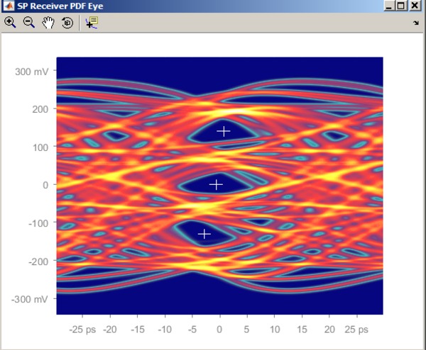
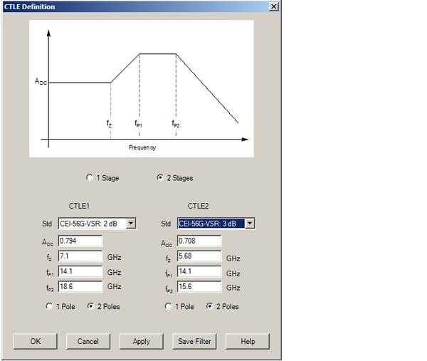
The PAM-4 analysis has full signal path emulation tools that support Continuous Time Linear Equalizer (CTLE), channel emulators described by S-parameters or TDR waveforms, and receiver equalizers Feed Forward (FFE) and Decision Feedback (DFE).
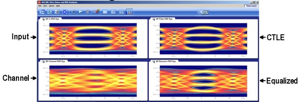
80SJNB analysis tools
The advanced techniques employed by the designs call for advanced tools in the measurement solutions. The concerns begin with acquisition: capturing the data signal through physical fixture distorts signal shape; 80SJNB provides you with a fixture de-embedding feature1which allows you to remove the effects of the fixture from the measurement. The accuracy improvement might well mean the difference between a passing design and a failing one, because the impact of the fixtures on the signal fidelity today is large.
And what is the shape of the transmitter signal you are capturing? The signal from the transmitter is no longer a simple NRZ square-wave pattern. Transmitter designers alleviate high-frequency loss in the media with transmitter equalization features, for example with preemphasis or de-emphasis of the transmitter waveform. Correspondingly, transmitter signals today need to be evaluated for this transmitter equalization; your 80SJNB quickly provides equalizing tap weight results to give you insight into the quality of your transmitter for both single- and multi-tap transmitter equalization designs.
1The tool for de-embedding filter creation is available free of charge from your Tektronix sales office.
Measure jitter and noise
80SJNB revolutionized jitter analysis by adding noise analysis, critical to noise- and eye-closure-limited high-speed designs both for NRZ (PAM-2) and PAM-4 signals. Complete characterization of both jitter and noise allows 80SJNB to offer capability new for oscilloscopes – BER contours, found on BERT instruments like the Tektronix BERTScope Series.
80SJNB offers analysis that is aware of bounded uncorrelated disturbers (BUJ etc.). Bounded uncorrelated disturbers are a growing problem in fast, densely packed designs at 8 Gb/s and above, where they arise mostly from increased crosstalk. In older jitter and noise analysis tools they are typically mistaken for random, unbound components; classifying these components as unbound leads to inappropriate increase in random component breakdown (RJ) and total (TJ, TN) result. 80SJNB answers the challenge with a jitter and noise breakdown extended to properly classify the bounded uncorrelated disturbers in their own category, increasing the accuracy of the jitter/noise result.
Unique among jitter tools, 80SJNB breaks down the contribution of noise to jitter with RJ(v) and PJ(v). The breakdown quickly pinpoints the cause of jitter problems.
Beyond measurements at the transmitter
An important part of today’s evaluation of serial data links is the complicated interaction between the shape of the measured waveform and the complex behavior of the interconnect channel. It is no longer possible to assume that if transmitter output meets the eye diagram mask it will work against all channels up to a given loss. Instead, advanced link test methods acquire the true transmitter waveform shape, and test against several corner-case channels.
Is the solution of emulating the channels based on their network description, for example, S-parameters? Such compliance tests are becoming a part of new standards. Now the measurement suite on your transmitter under test simply involves acquisition of the transmitter signal. Then you connect the captured signal to all required channels, one channel at a time – in emulation, rather than physically. 80SJNB supports this methodology; you can view the candidate channels without the need to reacquire the transmitter waveform. And unlike bare-bones evaluation scripts often used for pass/fail decisions the 80SJNB offers a rich set of views of the signal, starting with complete waveform, oversampled for high signal fidelity.
And of course the complete set of 80SJNB jitter and noise measurements is available to support your analysis of what problems, if any, your device might have. At the same time the BER eye offers a view of the link performance that matters most to the end user – in terms of BER performance and its margins. At the end of the test, save the waveform description data set for evidence or for future experiments; then recall and reanalyze whenever is needed without the need to reacquire.
80SJNB BER
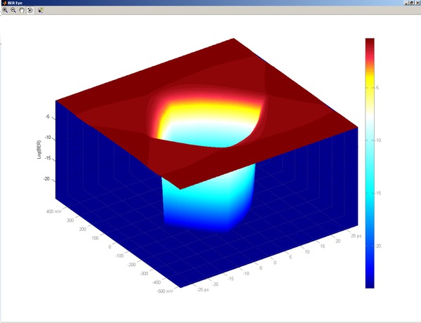
Perhaps the single most important result of serial data link test is the BER; uniquely, the 80SJNB brings you the BER eye plot. While measurements on narrow parts of the signal are now common (jitter at the crossing, noise at the cursor), 80SJNB captures the whole signal, and then truthfully presents the accumulation of all impairments. Measurement results at a different decision threshold or timing point are just a click away, as the 80SJNB always keeps the whole 3-D shape and all waveforms behind it.
Mask testing
The communication industry (e.g. IEEE 802.3 100GBASE-LR4) has evolved mask testing from a basic test done on acquired data to a statistical-based methodology. In the past, testing was done by measuring the hit-ratio on the acquired eye and thus was done at a shallow BER. Statistical-based methods improve the repeatability and efficiency of the mask test on a larger population of data and as a direct result improve the ability to separate good and bad transmitters.
80SJNB Essentials adds support for the hit-ratio mask test and includes masks for common standards. Mask testing can be done on the waveform data or after de-embedding, channel emulation or equalization (requires 80SJNB02).
The 80SJNB Mask test goes beyond the standards’ methodology and adds two new concepts:
First, you are not limited to measuring the eye diagram at the probability given by the acquired data, but can also measure at other probabilities calculated in the PDF space. For example, the hit ratio for a standard mask test may be one hit in 20,000 samples. This is supportable by the traditional mask testing available in an oscilloscope. However, for a hit ratio of one hit in 10 million samples, traditional mask testing would require an excessively long acquisition time; 80SJNB quickly calculates both of these hit ratios.
Second, since 80SJNB also calculates the BER eye surface, you can apply the mask test to a target Bit Error Ratio (such as the BER contour space). In other words, you can find the Bit Error Ratio for a given mask (a BER mask test). This approach provides a different insight into the overall system quality.
The PDF mask test is the traditional industry approach to assess the quality of a transmitter. The BER Mask test provides a test of the BER that the signal supports for the given mask. When a custom mask shape is needed, for example, based on a change in requirements, the shape can be easily modified in an ASCII file and used in either of the PDF or BER space.
De-embed, embed, and equalize
SDLA Visualizer and JNB Signal Path
JNB's Signal Path is now complemented with the advanced features of SDLA Visualizer. SDLA Visualizer extends the de-embedding and channel emulation capabilities of JNB signal path by offering a complete 4-port de-embed that models not only the effects of insertion loss, but also models the effects of return loss and cross-coupling. SDLA Visualizer also complements the DFE/FFE receiver equalization support in JNB and adds the ability to model CTLE equalization.
SDLA Visualizer works with the Signal Path function built into JNB Advanced. After configuring SDLA Visualizer, selecting the desired test point, and applying the model, the filter for the selected test point will automatically be loaded into the Signal Path filter block.
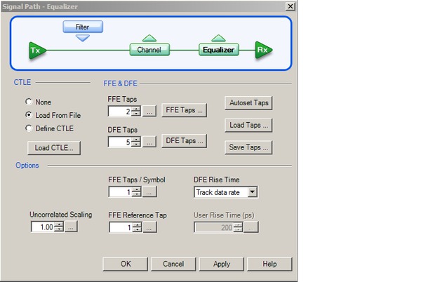
If DFE or FFE equalization are required, those parameters can be quickly entered in the JNB Signal Path and then the final measurements can be done.
These are just a few examples of the many features available from SDLA Visualizer, for more details see the SDLA Visualizer datasheet available onwww.tektronix.com.
Transmitter equalization measurements
Serial data transmitters employing pre-emphasis/de-emphasis can be evaluated and measured using the FFE equalization feature. The package can autoset the tap values on the received PRBS pattern, enabling evaluation of the value of taps that counter-equalize the transmitter pre-emphasis/de-emphasis.
Fixture removal, arbitrary filter
At high speeds the test fixture often significantly distorts the acquired signal. The Advanced package supports a filter block which can be used for the fixture removal. But the processing block is flexible, not dedicated; it can perform as an arbitrary filter instead, for example for simulation of pre-emphasis/de-emphasis schemes or for the use of filters created with SDLA Visualizer.
Channel emulation
The interaction between the true transmitter signal shape and the channel (interconnect) parameters is complex and not easily predictable from separate measurements. A reliable way to observe the performance of the whole serial link is by connecting the true transmitter waveform to the channel. The channel doesn’t have to be physically present: the Advanced 80SJNB package offers channel emulation based on network measurements of the channel. In this situation a transmitter signal with or without pre-emphasis/de-emphasis can be captured; the channel can be emulated through its S-parameters or time-domain network description, such as the TDR/TDT traces, and the signal at the end of the emulated channel can be measured.
Equalize, then equalize again
The equalization in the transmitter is one tool in the arsenal of tricks for fighting the loss and dispersion in the interconnect: another one is the equalization at the receiver. Receiver equalization in most NRZ systems falls under either FFE (Feed Forward Equalization; also known as LFE – Linear Feedback Equalization), or DFE – Decision Feedback Equalization. A receiver equipped with equalization can decode signals that, when viewed as an eye diagram, are completely closed.
How to measure such signals? The 80SJNB equalization tools can open a completely closed eye, with your own equalizer tap values, or, at the push of a button, find equalization tap values on a PRBS pattern for you, for either a FFE or DFE equalizer. The speed of recalculation and the ease of use allows you to easily modify system parameters, such as the number and weight of taps, or the amount of pre or de-emphasis; you can verify the optimization of the design, or develop “what-if” scenarios.
For those cases where CTLE (Continuous Time Linear Equalization) is required SDLA Visualizer can quickly create the necessary filter and load it directly in JNB.
If you design or measure devices intended for the high-volume PC market you will appreciate the addition of operation on the SSC (Spread Spectrum Clocking) – another first in the sampling oscilloscope measurements. Using the DSA8300 or DSA/TDS/CSA8200 mainframes plus the 82A04 Phase Reference module, the 80SJNB not only measures your signals under the presence of SSC, it also measures the SSC parameters.
Beyond just analysis, 80SJNB presents the unmatched utility of separating the jitter caused by noise impairments versus its jitter-based component.
The platform
The 80SJNB Jitter, Noise, BER, and Serial Data Link Analysis software runs on the Tektronix DSA8300 Sampling Oscilloscope. This combination of state-of-the-art analysis software with the advantages of the Tektronix sampling oscilloscope mainframe, such as modular flexibility, uncompromised performance, and unmatched signal fidelity, gives you the tools for next-generation high-speed serial data design validation and compliance testing.
Network description tool
The 80SJNB Jitter, Noise, BER, and Data Link Analysis software in some cases uses network description information, such as S-parameters in the Touchstone format. We recommend Tektronix TDR hardware and Tektronix IConnect application software for high-quality Touchstone network description data. Amongst the advantages of using Tektronix TDR hardware and IConnect is the preservation of the DC values in the Touchstone matrix, which is typically lost with other measurement methods. 80SJNB will work with network description based on other measurement methods, such as VNA data; the DC measurement results will then typically have to be extrapolated in the 80SJNB.
Prerequisites
The 80SJNB software package is designed for use on the DSA8300 Sampling Oscilloscope.
Spread Spectrum Clocking (SSC) support requires the 82A04 Phase Reference module, which can only be used on the DSA8300.
80SJARB: Jitter analysis of arbitrary data
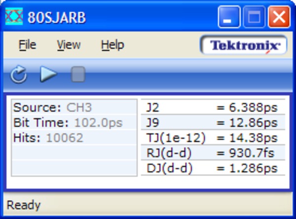
The 80SJARB jitter measurement application software for the Tektronix DSA8300 addresses IEEE 802.3ba applications requiring the J2 and J9 jitter measurements. It also enables basic jitter measurements for NRZ data signals including PRBS31, random traffic, and scrambled data. This provides an entry-level jitter analysis capability with simple Dual Dirac model jitter analysis and no hardware module requirements. 80SJARB can acquire continuously in “free run” mode, delivering acquisitions and updates beyond the IEEE minimum requirement of 10,000 data points. Plots include jitter bathtub curves for both measured and extrapolated data and a histogram of the acquired data.
Supported 80SJNB, 80SJARB measurements
80SJNB, 80SJNB02, PAM-4 Advanced Jitter, Noise, BER Analysis measurements
| Measurement | Description (per every eye when PAM4) |
|---|---|
| BUJ (d-d) | Bounded uncorrelated jitter (Dual Dirac) |
| BUN(d-d) | Bounded uncorrelated noise (Dual Dirac) |
| DCD | Duty cycle distortion |
| DDJ | Data dependent jitter |
| DDN | Data dependent noise |
| DDN (lower) | Data dependent noise on low level |
| DDN (upper) | Data dependent noise on high level |
| DDPWS | Data dependent pulse width shrinkage |
| DJ | Deterministic jitter |
| DN | Deterministic noise |
| Eye Opening @ BER | Horizontal eye opening |
| Eye Opening @ BER | Vertical eye opening at specified BER |
| Jx @ BER | Defaults to J2, BER = 2.5e-3 |
| Jy @ BER | Defaults to J9, BER = 2.5e-10 |
| NPJ(d-d) | Non periodic jitter (Dual Dirac) |
| NPN(d-d) | Non periodic noise (Dual Dirac) |
| OMA | Optical Modulation Amplitude |
| PJ | Periodic jitter |
| PJ(h) | Horizontal component of periodic jitter |
| PJ(v) | Vertical component of periodic jitter |
| PN | Periodic noise |
| PN(h) | Horizontal component of periodic noise |
| PN(v) | Vertical component of periodic noise |
| RJ (RMS) | Total measured random jitter |
| RJ(d-d) | Random jitter in Dual Dirac model |
| RJ(h) (RMS) | Horizontal component of random jitter |
| RJ(v) (RMS) | Vertical component of random jitter |
| RN (RMS) | Total measured random noise |
| RN(h) (RMS) | Horizontal component of random noise |
| RN(v) (RMS) | Vertical component of random noise |
| SSC frequency | Spread spectrum modulation frequency (limited support) |
| SSC magnitude | Spread spectrum modulation magnitude (limited support) |
| TJ @ BER | Total jitter at specified BER |
| TN @ BER | Total noise at specified BER |
| VMA | Voltage modulation amplitude |
| 80SJNB PAM-4 global measurements | |
| Center Deviation | Position of eye centers relative to middle eye |
| Effective Symbol Level 1 | Effective symbol relative to average (L0, L1) |
| Effective Symbol Level 2 | Effective symbol relative to average (L2, L3) |
| EH6/EW6 OIF-CEI | PAM4 eye height and width, per specification |
| Level <e> | Symbol levels: L0, L1, L2, L3 |
| Level Deviation | Level separation relative to peak-to-peak |
| Level Linearity | PAM4 level linearity |
| Level Mismatch ratio (RLM)( | Minimum level separation relative to peak-to-peak |
| Level Thickness | Level RMS at minimum inter-symbol interference |
| Level Time Deviation | Minimum inter-symbol interference level positions |
| Minimum Signal Level | Minimum of level separations |
| OMA outer | Optical modulation amplitude between L0 and L3 |
| Transition Timing | Rise/Fall on individual PAM trajectories |
| Vertical Eye Closure | Minimum eye amplitude over eye opening |
- Plots: Jitter and Noise Components Probability Distributions, Spectral Distributions, Data Dependent Jitter and Noise and DDPWS vs. Bit, Data Pattern Waveform, Bathtub Curves for Jitter and Noise, BER Probability Map, BER Contour Diagrams, Q-Eye, Probability Distribution Eye Diagrams (Data pattern can be plotted after every Signal Path (SP) processing step), SSC (Spread Spectrum Clocking) Profile. When analyzing PAM-4 signals, plots for all three stacked eyes are shown. SSC support is deprecated above 12 GBd on PAM4.
- Data Logging: Query and Export of all Numeric Results. Export of Waveforms: Raw Acquired Pattern Waveform, Correlated Pattern Waveform, Correlated Pattern Waveform after Every Signal Path Processing Step, Probability Distribution Eye Diagrams, and Bathtub Curves.
- Mask Testing: Statistical mask testing in PDF or BER space. Mask hit ratio supported.
80SJARB basic jitter analysis of arbitrary data
| Measurement | Description |
|---|---|
| DJdd | Deterministic jitter (Dual Dirac model) |
| J2 | Total jitter for BER = 2.5e–3 |
| J9 | Total jitter for BER = 2.5e–10 |
| RJdd | Random jitter (Dual Dirac model) |
| Tj | Total jitter for BER = 1.0e–12 |
- Plots: Jitter/Eye Opening Bathtub, Histogram of Acquired Data.
- Free Run Mode: For continuous acquisitions and update beyond the IEEE minimum requirement of 10,000 data points.
Specifications
All specifications apply to all models unless noted otherwise.
Measurement characteristics
- Jitter Floor (DSA8300)
- With 82A04B: ≤100 fsRMS1
Without 82A04B: ≤400 fsRMS
1See 82A04B data sheet for details; 82A04B only supported in the DSA8300 and DSA8200 Series mainframes. See DSA8300 data sheet for details on jitter floor performance.
- Noise Measurement Accuracy
- Matches underlying hardware capability, see sampling module data sheet for specifications. Acquired waveform must be live. Acquired waveform must be a fixed repetitive pattern of maximum pattern length: 100k UI Network description in either Touchstone S-parameters (one-, two-, or four-port supported; single-ended and differential entry supported) or in time-domain ‘reference, waveform’ format (time-domain format *.wfm of 8000 Series supported; time-domain format *.wfm of IConnect® supported)
- Export Waveforms
- Raw (acquired) waveform, correlated filtered waveform after every step of the Signal Path
- Equalization Autoset Patterns
- PRBS3 through PRBS16 (any pattern that can be analyzed can be also equalized)
- Maximum SSC (spread spectrum clocking)1
- <5000 ppm analysis is supported
1SSC is currently supported to 12 Gb/s. Controlled length cables are required for SSC acquisition; contact your application engineer for an application note.
- Maximum Number of Taps, FFE/DFE
- 100/40; 1, 2, or 10 FFE taps / UI
- Arbitrary Filter Description
- Finite Impulse response Arbitrary Filter Description. Contact your Tektronix Technical Support Center (http://www.tek.com/service/) for other formats / format convertors.
System requirements
- 80SJARB
- Windows 7 or Windows XP equipped 8000 Series mainframe
- 80SJNB
- DSA8300 Series mainframe configured with Option ADTRIG and with software release V5.*. MS Windows 7 (please contact the Tektronix field office for information on upgrading your mainframe if necessary)
DSA8200 or older series mainframe with 80A06 Pattern Sync Module (plugged into the oscilloscope, or on a SlotSaver cable)
Contact your local Tektronix sales office for details on configuring your existing TDS/CSA8200, TDS/CSA8000B, or TDS/CSA8000 to be compatible with 80SJNB
Ordering information
Models
- 80SJNB
- Jitter, noise, BER, and RIN/RINxOMA 1 measurement and analysis
- 80SJNB02
- Adds the following features to the 80SJNB package for SDLA support:
Fixture de-embedding/arbitrary linear filter support
Channel emulation (based on channel time- or frequency-domain measurements)
FFE/DFE Equalizer support
- 80SJNB PAM4
- Comprehensive analysis of PAM-4 signaling
- 80SJARB
- Basic jitter measurements
1RIN and RINxOMA measurements are taken using the TekExpress RIN application which is distributed with the 80SJNB and 80SJNB01 software.
DSA8300 preinstall options
Order the following options to preinstall 80SJARB, 80SJNB, or related software in a DSA8300 instrument:- Option JARB
- Add 80SJARB to DSA8300
- Option JNB
- Add 80SJNB Essentials to DSA8300
- Option JNB01
- Add 80SJNB Advanced to DSA8300
- Option JNB02
- Add 80SJNB Advanced with SDLA Visualizer to DSA8300
- Option PAM4
- Add PAM4 Transmitter Analysis Software to DSA8300. Requires option JNB01 (80SJNB Advanced) or option JNB02 (80SJNB Advanced with SDLA Visualizer) software
- For users of the original (80SJNB V1.*) package, the 80SJNB Essentials (V2.*) is a free update. Download the free update from www.tek.com.
- You do not need to order 80SJARB when ordering 80SJNB, 80SJNB01, or 80SJNB02; it is included at no additional charge.
- 80SJARB is available to all licensed users of any version of 80SJNB at no charge. Simply download 80SJARB from the Tektronix Web site.
Instrument upgrade options

Note: All 80SJNB-related options requires the DSA8300 ADVTRIG option (advanced triggers with pattern synchronization).
| Instrument | Upgrade name | Upgrade option | |
|---|---|---|---|
| DSA8300 | DSA83UP | JNB | Add 80SJNB Essentials to DSA8300 |
| JNB01 | Adds 80SJNB Advanced version 1 | ||
| JNB02 | Add 80SJNB Advanced version 2 (SDLA Visualizer) | ||
| PAM4 | Adds PAM-4 analysis (requires 80SJNB01 or 80SJNB02) | ||
| JARB | Add 80SJARB to DSA8300 | ||
| ADDJNB01 | Upgrade 80SJNB Essentials to 80SJNB01 | ||
| JNBTOJNB02 | Upgrade from 80SJNB Essentials to 80SJNB02 | ||
| JNB01TOJNB02 | Upgrade 80SJNB01 to 80SJNB02 (SDLA Visualizer) | ||
| DSA8200 | DSA82UP | JNB | Add 80SJNB Essentials |
| JNB01 | Add 80SJNB Advanced version 1 | ||
| JNBADD01 | Upgrade from JNB to JNB Advanced |


