Contact us
Call us at
Available 6:00 AM – 5:00 PM (PST) Business Days
Download
Download Manuals, Datasheets, Software and more:
Feedback
10BASE-T1S Automotive Ethernet Compliance Test Solution
Option 5-CMAUTOEN10 and 6-CMAUTOEN10 Datasheet

Get more visibility into your Automotive Ethernet designs with 10BASE-T1S Automotive Ethernet Compliance Test Solution for the 5 Series and 6 Series B MSOs Mixed Signal Oscilloscope. The combination of the oscilloscope, analysis software, and a wide range of available analog probes enable you to perform detailed and accurate amplitude and timing measurements on your designs. The integration of Automotive Ethernet is placing greater demands on technology and is placing even greater demands on comprehensive design validation to ensure interoperability between multiple Electronic Control Units (ECU) and reliability in demanding environments. A complete testing solution enables passing strict compliance tests and provides greater confidence in design margins under real world conditions.
Key features
- Test time: Fully automated with a setup wizard to perform compliance testing as per the 10BASE-T1S (IEEE 802.3cg™) standard. Highly optimized and intuitive user interface for quick test configuration and validation of electrical signals. The 5-CMAUTOEN10/6-CMAUTOEN10 software automatically configures equipment per the test requirements which reduces overall test execution time.
- Test coverage: The TekExpress Automotive Ethernet solution for 10BASE-T1S is designed to comply with the IEEE 802.3cg™ specification covering transmitter testing.
- Validation and debug: Tools such as Advanced Jitter Analysis (DJA) let you identify problems before compliance testing or in the event of a failure.
- Comprehensive report: Automated reporting with Pass/Fail status and screen shots of the waveforms.
- Measurement accuracy: Tektronix 5 series and 6 series B Mixed Signal Oscilloscopes offer analog bandwidth up to 8 GHz, sample rates up to 25 GS/s and 12-bit analog-to-digital converters (ADC), delivering the performance needed to capture waveforms with high signal fidelity and resolution.
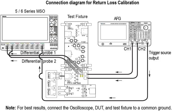
- Domain measurements: Time domain and frequency domain measurements (Return Loss and Power Spectral Density) can be made with a single instrument. Tektronix' patented measurement approach in the TekExpress Automotive Ethernet Test Solution enables designers to perform return loss measurements using an oscilloscope, reducing the need for additional test equipment.
- Performance verification: The Automotive Ethernet application enables you to easily run tests multiple times. The statistics in the reports display Pass/Fail status for each run to help study device performance over different runs.
Fully automated compliance testing
The Tektronix 5-CMAUTOEN10/6-CMAUTOEN10 Automotive Ethernet (10Base-T1S Short Reach) automated compliance test solution is a fully automated compliance test application for the 10BASE-T1S (IEEE 802.3cg™) standard. Executing all the measurements manually is extremely time-consuming. The TekExpress Automotive Ethernet application provides an automation framework that enables you to execute all the measurements with minimal intervention, only when you need to change connections.
The physical layer compliance tests are defined to ensure interoperability between different designs and hardware vendors. The requirements to perform these tests have been expanded and now cover Automotive Ethernet 10BASE-T1S standards.
The test suite runs on 5 Series and 6 Series B MSOs, and lets you to take full advantage of the oscilloscope validation and debug capabilities in addition to compliance testing. The Tektronix Automotive Ethernet Solution provides greater confidence in design margins under real world conditions by ensuring that your designs pass the strict 10BASE-T1S compliance tests.
| Test Name | Test Mode | Instrument |
|---|---|---|
Transmitter Output Droop | 2 | 350 MHz Oscilloscope |
Transmitter Timing Jitter | 1 | |
Transmitter Power Spectral Density (PSD) | 3 | |
Transmitter Clock Frequency | 1 | |
Peak Differential Output | 1 | |
MDI Return Loss | Slave Idle Mode | 350 MHz Oscilloscope and AFG or Tektronix VNA |
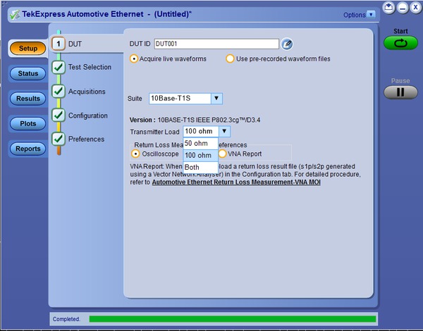
The 5-CMAUTOEN10/6-CMAUTOEN10 TekExpress Automotive Ethernet software allows for complete or selective testing of any of the transmitter electrical specifications. Tests are configured by following a step-by-step process. Software navigation follows a logical workflow for quick test setups, configurations, and review of test results. The software sets up the oscilloscope and automates the tests, guiding you to accurate and repeatable results.
Test setup configurations vary greatly in terms of connections to the device under test, probing, test fixtures, calibration, and use of the oscilloscope and signal generator. To help you to correctly set up for a measurement, the Automotive Ethernet software provides setup instructions for each test, with images and reference illustrations, to ensure the correct setup.
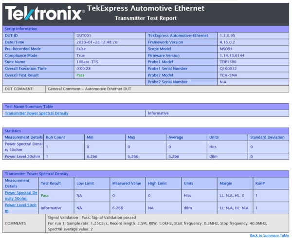
The application generates a comprehensive, date-stamped test report with pass/fail results, waveforms, and data plots.

The 5-CMAUTOEN10/6-CMAUTOEN10 TekExpress Automotive Ethernet compliance software requires a Tektronix 5 Series or 6 Series B MSOs with Option 5-WIN/6-WIN or SUP5-WIN/SUP6-WIN (Microsoft Windows 10). Since it operates as a Windows application, the software shares the oscilloscope display. For convenience, we recommend that you add an external monitor to display the compliance software and test reports separately from the oscilloscope screen.
Return loss measurement
The MDI return loss test determines the impedance mismatch between PHY and reference MDI Connector from the differential impedance specification of 100 Ω, which will affect hardware interoperability. Return Loss is a frequency domain measurement and generally requires an additional frequency domain test instrument to run the measurement. Using a patented technique, you can perform an MDI return loss measurement using oscilloscope and function generator. To learn more about return loss measurement using oscilloscope, please refer to Patent No US007271575B2.

Transmitter clock frequency and jitter measurements
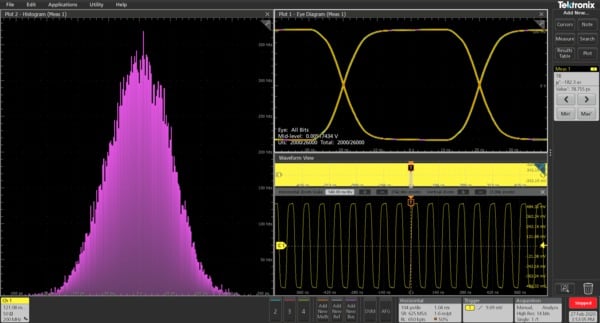
Jitter tests quantify the timing variations of the edges of the signal, using specified test patterns. These jitter measurements include contributions from duty cycle distortion and baseline wander. The jitter peak-to-peak measurement is determined by the minimum and maximum values in the tails of the histogram. The DUT is set to test mode 1.
Droop measurement
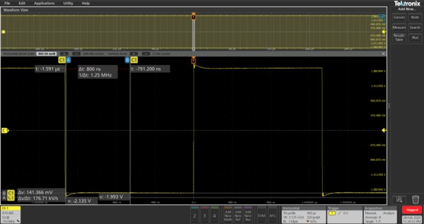
The droop measurements are performed by determining the positive and negative waveform peak voltages. The DUT is set to test mode 2.
Power spectral density measurement
Power Spectral Density (PSD) is a frequency domain measurement that is often performed using a spectrum analyzer. The 5 Series and 6 Series B MSOs, with 12-bit analog-to-digital converters (ADC) and outstanding noise performance, provides accuracy similar to a spectrum analyzer. The spectrum of an input signal in test mode is computed using built-in oscilloscope math functions. The post-processing is done on the signal to determine the PSD. The computed PSD is then compared with the upper and lower masks as defined in the specification to arrive at the final result. 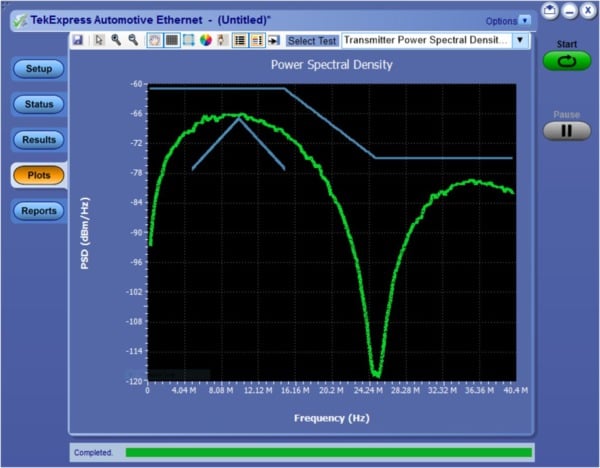
Limits
The 10BASE-T1S Automotive Ethernet can operate in point-to-point or multi-drop mode. In point-to-point connections, devices operate at 100 ohm impedance but in other cases devices operate at 50 ohm impedance. The IEEE specifies measurement limits for 100 ohm and 50 ohm impedances. The Tektronix 5-CMAUTOEN10/6-CMAUTOEN10 10BASE-T1S Automotive Ethernet compliance software allows you to configure limit depending upon the device configuration. The application can work in compliance mode, where limits are defined per compliance specifications, or in user defined mode, which allows you to edit the limits to perform characterization of the DUT.
Validation and debug
Validation and debugging are easily accomplished early in the design process and ahead of final compliance testing with the 5 Series and 6 Series B MSOs. The oscilloscopes' standard measurement set, along with the optional DJA (Advanced Jitter and Timing Analysis) software supports several key compliance tests including:
Clock frequency
Transmitter amplitude with histogram
Full characterization of jitter performance including Time Interval Error (TIE)
Histogram profiles
This type of early testing increases the likelihood of passing compliance tests, while allowing more complete characterization and determination of design margins. Master and slave jitter measurements can be particularly challenging given the tight compliance limits and the need to eliminate any possible sources of random or deterministic jitter.
Pass/fail reports
The 5-CMAUTOEN10/6-CMAUTOEN10 Automotive Ethernet (10Base-T1S Short Reach) automated compliance test application creates compliance test documentation quickly with a summary report in MHL or PDF format. The software automatically generates a report after test execution is complete, and includes Pass/Fail status to help you quickly analyze the test results. The report also includes test configuration details, waveform plots, oscilloscope screen shots, and margin analysis to provide more insights into your design.
6 Series B MSO Oscilloscope
With up to 10 GHz analog bandwidth, 50 GS/s sample rates, lowest noise and highest resolution, the 6 Series B MSO oscilloscope has the performance you need to capture waveforms with the best possible signal fidelity. 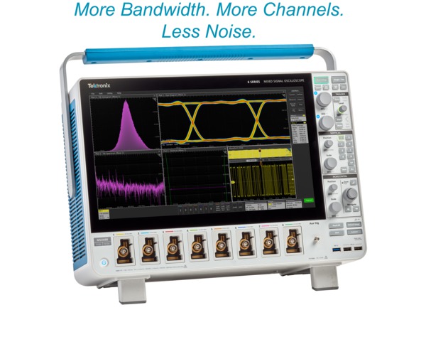
At the heart of the 6 Series B MSO oscilloscope are 12-bit analog-to digital converters (ADCs) that provide 16 times the vertical resolution of traditional 8-bit ADCs. This resolution, combined with an extremely low-noise front end, allows you capture small signal details even on relatively large signals.
Test fixtures and probing test points
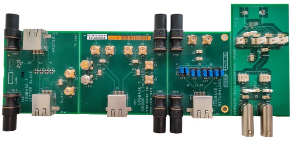
Accurate and repeatable compliance testing requires access to the PHY transmitter output. The recommended approach is to use the Tektronix TF-XGbT Ethernet fixture. These fixtures can support all test setups while providing convenient test points for probing. If there is a provision to probe directly on DUT, user can perform compliance test without fixture.
Ordering information
Measurements and required hardware
| Measurements | Required hardware |
|---|---|
Transmitter Output Droop Transmitter Timing Jitter Transmitter Clock Frequency Differential Output Transmitter Power Spectral Density | 5 Series or 6 Series B MSOs with a probe (TDP1500, P6247 or P6248) |
Return Loss | 5 Series or 6 Series B MSOs AFG31102 2 Nos TDP1500, P6247 or P6248 probes |
Required hardware
| Product | options |
|---|---|
| Oscilloscope | 5 Series MSO with minimum bandwidth of 350 MHz (option 5-BW-350) or 6 Series B MSO (Option 5-WIN/6-WIN or SUP5-WIN/SUP6-WIN- removable SSD with Microsoft Windows 10 operating system) |
| Signal generators | Tektronix AFG31102 |
| Probes | TDP1500, P6247 or P6248 (requires use of TPA-BNC adapter) |
Required software
| Product | Options |
|---|---|
| Automotive Ethernet (10Base-T1S Short Reach) automated compliance test solution | Option 5-CMAUTOEN10/6-CMAUTOEN10 or SUP5-CMAUTOEN10/SUP6-CMAUTOEN10 |
Optional software
| Product | Options |
|---|---|
| Advanced Jitter and Eye Analysis | Option 5-DJA/6-DJA or SUP5-DJA/SUP6-DJA |
| Automotive Ethernet Signal Separation | Option 5-AUTOEN-SS/6-AUTOEN-SS |
| PAM3 Analysis | Option 5-PAM3 or 6-PAM3 |
| 100BASE-T1 Protocol Decode | Option 5-SRAUTOEN1 or 6-SRAUTOEN1 |
| 125 M record length | Option 5-RL-125M/6-RL-125M or SUP5-RL-125M/SUP6-RL-125M |
| CAN, CAN FD, LIN, FlexRay serial bus trigger and decode | Option 5-SRAUTO/6-SRAUTO or SUP5-SRAUTO/SUP6-SRAUTO |
| SENT Protocol trigger and decoder | Option 5-SRAUTOSEN/6-SRAUTOSEN or SUP5-SRAUTOSEN/SUP6-SRAUTOSEN |
| I2C, SPI serial bus trigger and decode | Option 5-SREMBD/6-SREMBD or SUP5-SREMBD/SUP6-SREMBD |
Recommended accessories
| Product | Quantity |
|---|---|
| External PC monitor | 1 |
| TF-XGbT test fixture | 1 |
| SMA female to BNC male adapter | 2 |
| SMA cables for signal source connections | 3 cables of same length |
| 50 ohm SMA M terminator cap | 2 |
Additional accessories for Multidrop test
| Product | Quantity |
|---|---|
| SMA male to SMA female RF coaxial adapter connector three way splitter | 2 |
| 50 ohm SMA M terminator cap | 4 |
| SMA male to SMA male RF coaxial cable adapter | 2 |
| SMA female to female adapter | 2 |


