Kontaktaufnahme
Live-Chat mit Tektronix-Vertretern. Verfügbar von 9 bis 17 Uhr CET Geschäftstage.
Anrufen
Kontaktieren Sie uns telefonisch unter
Verfügbar von 9 bis 17 Uhr CET Geschäftstage.
Download
Laden Sie Handbücher, Datenblätter, Software und vieles mehr herunter:
Feedback
PPG4001 PatternPro® Programmable Pattern Generator Datasheet
PPG4001 Datasheet
Die Produkte dieses Datenblatts gehören nicht mehr zum Angebot von Tektronix.
Tektronix Encore nach aufgearbeiteten Testgeräten durchsuchen.
Garantie- und Supportstatus dieser Produkte überprüfen.
Weitere Informationen
- PatternPro® PPG Series Multi-channel Pattern Generator
- Weitere Bitfehlerraten-Tester Modelle entdecken
Online lesen:

PPG4001 Datasheet
The Tektronix PPG4001 PatternPro® programmable pattern generator provides stressed pattern generation for high-speed Datacom testing.
Notice to EU customers
This product is not updated to comply with the RoHS 2 Directive 2011/65/EU and will not be shipped to the EU. Customers may be able to purchase products from inventory that were placed on the EU market prior to July 22, 2017 until supplies are depleted. Tektronix is committed to helping you with your solution needs. Please contact your local sales representative for further assistance or to determine if alternative product(s) are available. Tektronix will continue service to the end of worldwide support life.
Key performance specifications
- Low inherent jitter (typical RJ 150 fs @40 Gb/s)
- 11 ps typical 20% to 80% rise/fall times
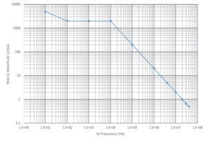
- Low frequency, high amplitude jitter insertion range of 10 Hz to 10 MHz at up to 5000 UI (with Option LFJIT)
- High frequency jitter insertion, including SR, RJ, and BUJ with amplitudes up to 50 ps (with Option HFJIT)
- Adjustable output voltage
Key features
- DC coupled differential data outputs
- Full rate and sub-rate multiple clock outputs
- Pattern trigger output
- Built-in adjustable clock source
- PRBS and user defined patterns
- Front panel touch screen GUI and USB computer control
Applications
- Semiconductor device testing
- Optical component testing
- Transceiver module testing
Product description
The Tektronix PPG4001 PatternPro® programmable pattern generator provides an unparalleled combination of industry leading performance, features, and ease of use. Design validation of today’s demanding high-speed applications requires instruments that produce the highest quality signals and enable programmable controls while being simple and easy to use.
Fast rise time and low jitter are critical performance parameters and the PPG4001 delivers typical 150 fs inherent RJ with 11 ps rise time. Within seconds of powering up the instrument, a first time user can be creating high-performance programmable patterns to test a DUT. In addition, the PPG4001 offers comprehensive jitter insertion for stressed receiver testing and similar applications.
The PPG4001 may be paired with the PED4001 40 Gb/s programmable error detector to provide a complete BERT system that includes control and analysis software.
Typical 40 Gb/s eye diagram
Specifications
All specifications are guaranteed unless noted otherwise. All specifications apply to all models unless noted otherwise.
Data outputs
- Voltage amplitude
- Each positive and negative differential output is independently programmable.
- Single-ended
- 300 mV to 1.0 V
- Differential
- 600 mV to 2.0 V
- Offset window
- -2 V to +3.3 V, programmable/adjustable
- Termination voltage range
-
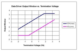
-2.0 V to +3.3 V window. Programmable/adjustable. Applied by user via 50 Ω.
This setting is used in cases where the load being driven is terminated at a level other than zero volts. The effect of termination voltage on the output voltage is shown in the following figure. To ensure proper operation, never load the output with a termination voltage less than Voh minus 3 V.

- Rise/fall time
- Scope bandwidth can impact the measured signal rise time.
- 20 to 80%
- 11 ps, typical
- 10 to 90 %
- 16 ps, typical
- Data output jitter
- Measured at 40 Gb/s with 211-1 PRBS at 500 mVp-p, single ended
- Total jitter (1E-12)
- 7 psp-p, typical
- Random jitter
- 200 fs, RMS, typical
- Connector type
- 2.4 mm
- Output impedance
-
- 50 Ω
- Single-ended
- 100 Ω
- Differential
Clock outputs
- Full rate clock output
- AC coupled, single-ended
- Frequency
- 20 GHz to 40 GHz
- Amplitude
- 500 mVp-p, typical
- Connector type
- 2.4 mm
- Half rate clock output
- AC coupled, differential
- Amplitude
- 400 mVp-p, typical
- Connector type
- 2.4 mm
- /n clock output
- AC coupled, single ended
- Programmable divider
- n = 2, 4, 8, 16
- Amplitude
- 500 mVp-p typical
- Connector type
- 2.4 mm
- Trigger output
- Programmed as pattern trigger or clock/n (with n = multiples of 128)
- Amplitude
- -500 mV to 0 V, DC coupled
- Connector type
- SMA
Data patterns
- Pattern type
- Data (from memory) or PRBS
- Data rate
- Programmable/adjustable
- Range
- 4 Gb/s to 40 Gb/s
- Resolution
- 10 kb/s
- Accuracy
- ±5 ppm
- PRBS pattern lengths
-
- 27 -1 bits
- Polynomial = X7 + X6 + 1
- 29 - 1 bits
- Polynomial = X9 + X5 + 1
- 211 - 1 bits
- Polynomial = X11 + X9 + 1
- 215 - 1 bits
- Polynomial = X15 + X14 + 1
- 223 - 1 bits
- Polynomial = X23 + X18 + 1
- 231 - 1 bits
- Polynomial = X31 + X28 + 1
- Data pattern depth
-
- Range
- 2 to 4,194,304 bits
- Resolution
- 1 bit
- Programmable error insertion
- Error insertion can be enabled with either single bit error insertion or at a programmable rate.
- Single bit errors
- Yes
- Programmable bit errors
- 10-3 to 10-15 BER
Jitter insertion
- High frequency jitter insertion option
- Add-on option for the instrument. Sum of external, internal sine, internal noise, and BUJ. Exceeding the range can generate errors.
- Total modulation range
- 50 psp-p
- Built-in sine source
- Programmable from either the front panel touch screen or remote control.
- Frequency range
- 5 kHz to 100 MHz
- Amplitude range
- 0 to 50 psp-p
- Accuracy
- ±10%, typical
- Built-in random noise source
- Programmable from either the front panel touch screen or remote control.
- Amplitude range
- 0 to 5 psRMS
- Accuracy
- ±10% typical
- Built-in BUJ source
- Programmable from either the front panel touch screen or remote control.
- Amplitude range
- 0 to 50 psp-p
- Modulation data rates
- 100 Mb/s to 2.5 Gb/s
- PRBS sequences
- 7,9,11,15,23,31
- Filter values
- 25/50/100 MHz filters
- External modulation input
- DC coupled, 3 dB bandwidths
- Frequency range
- DC to 100 MHz
- Amplitude range
- 0 to 50 ps p-p
- Maximum input
- 5 Vp-p
- Low frequency jitter insertion (Option LFJIT)
- Add-on option.
The specifications below apply when the data rate equals the internal clock rate frequency of 20 to 40 GHz. For each frequency octave below, the internal clock rate, the specifications below will be reduced by half. Thus when the data rate is 10 to 19.99999 Gb/s, the values below will be divided by 2. When the data rate is 5 to 9.99999 Gb/s, the values will be divided by 4.
Trigger system
- Trigger waveform
-
- Pattern mode
- 1 pattern per trigger for pattern length = multiple of 128
128 patterns per trigger for other pattern lengths
- Clock/n mode
- 128 through (232 - 128), n= any multiple of 128 in that range
- Duty cycle
- 50%, for either Pattern or Clock/n
- High level
- 0 V, typical
- Low level
- -500 mV, typical
- Output impedance
- 50 Ω, DC-coupled
- Connector type
- SMA
Clock inputs
- Frequency range
- 10 GHz to 20 GHz, half rate
- Input signal
- 500 mVp-p, typical, AC coupled
- Maximum input signal
- 800 mVp-p
- Input impedance
- 50 Ω, AC-coupled
Reference clock
- Input frequency range
- 10 MHz
- Input signal
- 1 Vp-p, typical, 50% duty square wave
- Maximum input signal
- 5 Vp-p, ±10 V DC, Damage threshold
- Input impedance
- 50 Ω, AC-coupled
- Output signal
- 1.2 Vp-p, typical, Square wave
- 10 MHz reference input/output
- Yes, BNC connector
Data error insertion
- Error insertion types
- Single or rate-based
- Error insertion rate
-
- Range
- 1 x 10⁻³ to 10-15 BER
- Resolution
- 3 digits
Control interfaces
- Front panel touchscreen GUI
- Yes, edit all instrument settings.
- Computer programmable interface
- USB TMC, program all instrument settings.
Physical characteristics
- Front panel width (with mounting tabs)
- 48.3 cm (19.0 in)
- Height
- 13.3 cm (5.25 in)
- Width
- 45.1 cm (17.75 in)
- Depth (rack mount)
- 35.1 cm (13.8 in)
- Weight
- 11.1 kg (24.5 lbs)
- Operating temperature
- 0 °C to 40 °C (32 °F to 104 °F)
Ordering information
Models
- PPG4001
- 40 Gb/s programmable pattern generator, 1 channel
Options
- PPG4001 LFJIT
- Low frequency jitter option for the PPG4001
- PPG4001 HFJIT
- High frequency jitter option for the PPG4001
Power plug options
- Opt. A0
- North America power plug (115 V, 60 Hz)
- Opt. A1
- Universal Euro power plug (220 V, 50 Hz)
- Opt. A2
- United Kingdom power plug (240 V, 50 Hz)
- Opt. A6
- Japan power plug (100 V, 50/60 Hz)
- Opt. A10
- China power plug (50 Hz)
- Opt. A11
- India power plug (50 Hz)
- Opt. A99
- No power cord
Manuals
- 071-3413-xx
- Printed PPG/PED Installation & Safety instructions
- 077-1089-xx
- PPG4001 User manual, PDF-only, downloadable from Tektronix.com


