Solutions to the Challenges of High Power ATE System Design
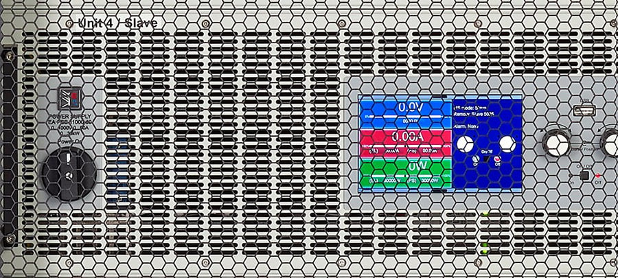
So, your assignment is to design a new high-power automated test equipment (ATE) system for a new product. Your challenge is to design a test system with maximum test performance to fully test the product within a pre-defined budget. Oh yes, the system must be reliable to avoid lost production time. The system must be online at all times except for maintenance shutdowns. Also, both the capital and annual operating costs of the system must be as low as possible; and it must take up a small amount of production floor space. Oh, one last thing. You have a deadline to get the system up and running, and it must meet the production throughput targets. Otherwise, revenue misses will be on your head.
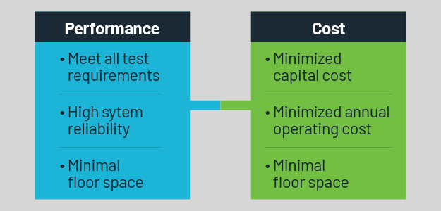
Figure 1. Performance vs cost challenges.
Let us help you meet all your requirements so you can sleep like a baby.
We will focus on a critical element in designing a high-power ATE system – the power instruments. Defining the power requirements for the ATE system significantly affects how well the system achieves the objectives of maximized test performance, minimized costs, and high reliability.
Meeting test performance requirements with maximized test capacity
Indeed, you should ensure that your power supply has the output performance to serve existing test requirements. You should also consider future needs, such as an electric vehicle (EV) manufacturer increasing its battery voltage in a future model. While a DC power supply with a rectangular output characteristic may be satisfactory for the original ATE system requirements, new product design changes could force you to purchase a new power supply since the rectangular output characteristic supply cannot adapt to the new requirements.
An autoranging output characteristic, as shown in Figure 1, outputs higher voltages and can supply higher currents than equivalent power supplies with rectangular output characteristics. Figure 1 contrasts an EA Elektro-Automatik (EA) 30 kW supply with two conventional output 22 kW power supplies. Note that the EA supply can output substantially higher voltage and higher current than the two rectangular output supplies. Furthermore, while the conventional rectangular output supplies can only deliver maximum power output at their maximum output voltage and maximum current (the top right corner of the output rectangle), the autoranging output supply delivers full power all along the curve between the two points, (1500 V, 20 A) and (500 V, 60 A).
EA has autoranging supplies that are unique in providing true autoranging and delivering full power down to 1/3 of the maximum output voltage. This capability allows you to test a product that operates over a wide voltage range and perform overvoltage and undervoltage tests with a single power supply. Using a rectangular output power supply could require using at least two power supplies.
For example, if an EV manufacturer converts to 900 V or higher from a 400 V battery design, you can use the same autoranging power supply in the EV battery test system. This saves total test system capital cost. You could have selected a higher output rectangular output power supply to plan for future changes. Still, the higher wattage supply penalizes you with higher capital costs and could take up more factory floor space.
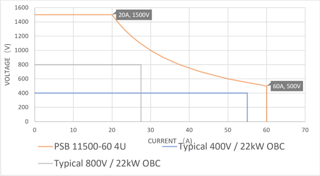
Figure 1. Autoranging output characteristic (red curve) compared with conventional rectangular output power supplies (blue lines). The autoranging power supply outputs full-rated power all along the red curve between 500 V and 1500 V. The rectangular supplies output full power only at one point, the upper righthand point on the line.
The same is true for electronic loads. Autoranging electronic loads, such as the new EA-ELR 1000 series, provide more sinking capacity with wider voltage and current ranges, enabling you to minimize the total load wattage needed for testing a product. A lower-power electronic load can reduce both the physical size of the test system and the cost of the test system.
Meeting complex test requirements with a simplified solution
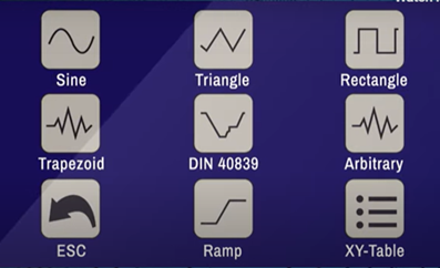
Maximizing test performance ensures the system can test to national and international standards. Avionics systems, automotive systems, and other products require testing to standards that can involve generating complex waveforms. Interfacing a signal generator into the system to modulate a DC power supply adds an extra instrument to the test system and adds complexity to the test system. EA supplies and DC electronic loads offer a built-in function generator that can safely and easily generate standard and custom waveforms. Figure 2 shows the variety of waveforms that both EA power supplies and loads can output (or sink for a load). Also, EA power supplies and loads can simulate battery, fuel cell, and solar.
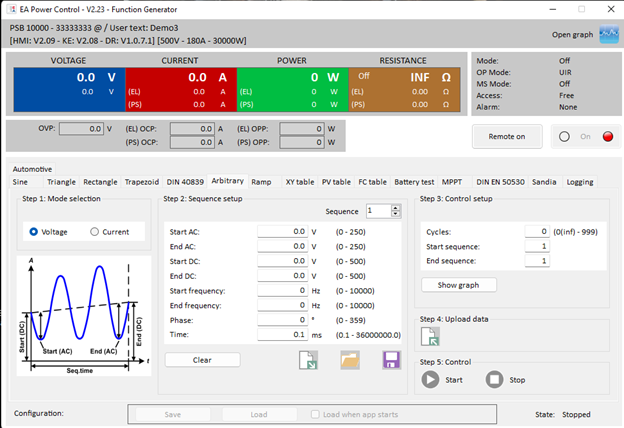
Figure 2. Waveshapes an EA instrument can generate. The picture on the top right illustrates the extent of standard and custom waveforms available. The PC display below the waveshapes shows an example of the parameters that the EA Power Control software can use to create a waveform.
Cell characteristics for more realistic testing of products powered by these sources. Thus, by using EA DC power supplies and loads, you can reduce ATE complexity by eliminating the need for extra instrumentation and not compromising on test requirements. This saves capital costs and test system size.
The need to acquire and control fewer instruments allows for faster development. A simplified system gives you a higher probability of transitioning a validated ATE system to production on schedule, allowing for maximizing revenue generation.
Minimizing capital costs and annual operating costs with bidirectional DC power supply equipment
Cost targets tend to compete with the need to meet test system performance requirements. Those conflicting objectives can have you looking to compromise on some aspects of instrument performance to keep costs within the capital budget. EA’s autoranging instrumentation can allow the use of a lower-power instrument compared with a power instrument with a rectangular output/input characteristic. In addition, as mentioned, the built-in function generator saves an extra instrument for signal generation requirements.
If the ATE system does not require simultaneous sourcing and sinking, then you can select a bidirectional DC power supply to perform both functions. See Figure 3. Furthermore, using instruments with a high capacity, such as the EA-PUB 10000 6U series Programmable Bidirectional DC Power Supplies with 60 kW power, provides numerous opportunities to save on the number of instruments needed for a high-power test system. High-capacity power instrumentation can help you build the ATE system within budget limitations.
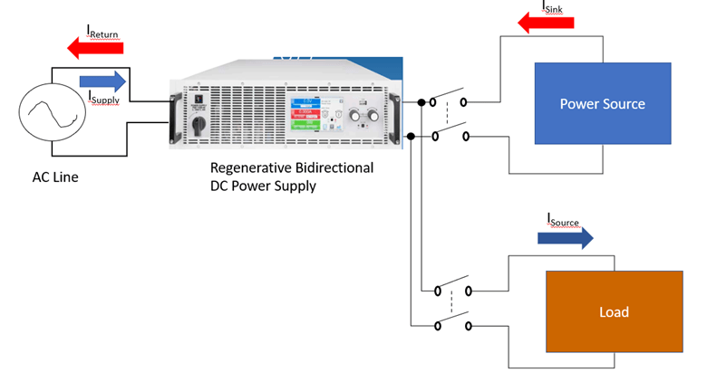
Figure 3. A bidirectional DC power supply combines a source and electronic load in one instrDiagram
Saving annual operating costs with regenerative loads
The efficiency of the power supplies and electronic loads is a huge factor affecting annual operating costs. You should look for power instrumentation that has high efficiency. Consider power supplies with both active power factor correction circuitry providing a power factor of approximately 0.99 and high-efficiency switch mode power supplies.
Also, consider instrumentation that returns energy to the power grid. Regenerative DC bidirectional power supplies and regenerative loads can return significant power to the power grid; in EA Elektro-Automatik’s case, its regenerative loads and supplies can return up to 96% of absorbed energy back to the grid.
Selecting high-efficiency power instrumentation can save substantial power consumption, which saves on utility costs. In addition, higher efficiency instrumentation and regenerative instrumentation run cooler, which can significantly reduce the capital and annual utility costs to maintain the ATE system at a safe temperature.
Saving manufacturing overhead costs
With fewer and lower power instruments, the ATE system can be smaller. When the test system requires 30 kW or as much as 60 kW capacity, EA supplies with high power density allow instrument sizes to be only 4U and 6U, respectively. The 6U power instruments, EA’s Industrial Series, has the highest power density available.
With EA instrumentation, you may be able to avoid the need for an additional test rack; or, you can build two systems into one DC power rack. If you can compress your test system, you can save precious manufacturing floor space, reducing cost-of-test overhead. The freed-up space can enable the addition of more test systems to allow increased production capacity within existing space leading to greater revenue.
Maximizing system reliability
ATE system downtime slows production output, leading to canceled orders and lost revenue. That is the reason management demands high ATE system reliability. There are several factors affecting reliability:
- Instrument selection
- System design
- Calibration procedures
- Manufacturer’s service and support.
The use of high-efficiency instrumentation and regenerative instrumentation improves reliability. More efficient instruments operate at a lower temperature putting less stress on components, and the instruments are less susceptible to failure than conventional power instrumentation. Furthermore, EA products conform to CE, UL and CSA standards. Attaining national-recognized testing lab approval builds confidence in product quality and reliability. All products include a standard 2-year warranty with options for 3- or 5-year warranties so you can demonstrate a lower annual cost of ownership.
Designing appropriate ventilation and cooling in the test rack, using proper grounding technique, and complying with test rack safety measures ensure good quality and stable measurements. You will want to pay attention to all the design details to enhance system reliability for optimal performance and high system uptime. EA has expertise in building DC power racks (see Figure 4) and can provide guidance.
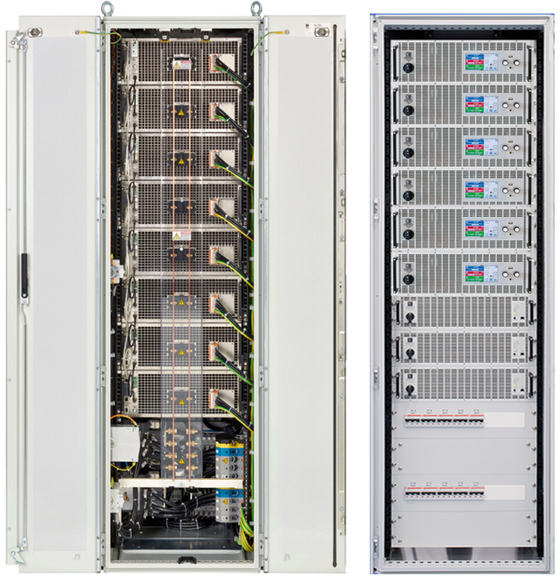
Figure 4. EA DC power racks conform to safety standards while providing proper grounding and power distribution wiring.
Many of you, particularly if you are in the aviation industry or automotive industry, will require evidence of ATE system calibration to international standards such as Z540 and ISO 17025. High-quality calibrations allow confidence that instruments will hold their calibration for at least the specified time interval. This enables you to more carefully predict when system downtime is needed, avoiding unplanned disruptions to production.
You will want to consider the support you can obtain from your power instrumentation vendor. That is especially important when test system engineering and manufacturing are in different locations. That suggests the need for a partner with global support capabilities.
EA can partner with you to overcome your challenges
Designing a cost-effective, high-performance, compact, energy-efficient ATE system involves numerous challenges. Be sure to consult with us to overcome the challenges of performance, cost, space, and future needs. EA has energy-efficient, compact power instrumentation with the features you need to achieve a high-performance ATE system within the allotted budget. EA helps you maximize performance and minimize annual operating costs over the life cycle of the ATE system. With our support, enjoy those restful nights. Learn more about EA Elektro-Automatik products.
Ready to learn more about ATE Test Systems? Read the white paper, Design and Build Cost-Effective High Power ATE Test Systems.


