
Suchen Sie nach dem richtigen Oszilloskop für Ihre Elektronik-Projekte oder Ihre beruflichen Vorhaben? Dieser Leitfaden bietet Ihnen eine klare Übersicht zur Auswahl des Oszilloskops, das Ihren Anforderungen am besten entspricht. Dabei spielt es keine Rolle, ob Sie ein erfahrener Ingenieur, ein Student oder ein Elektronikbastler sind. Wir gehen auf wichtige Parameter wie Bandbreite, Abtastrate und Anstiegszeit ein, um sicherzustellen, dass Sie eine fundierte Wahl treffen, die die Präzision und Effizienz Ihrer Messungen verbessert.
Wofür werden Oszilloskope verwendet?
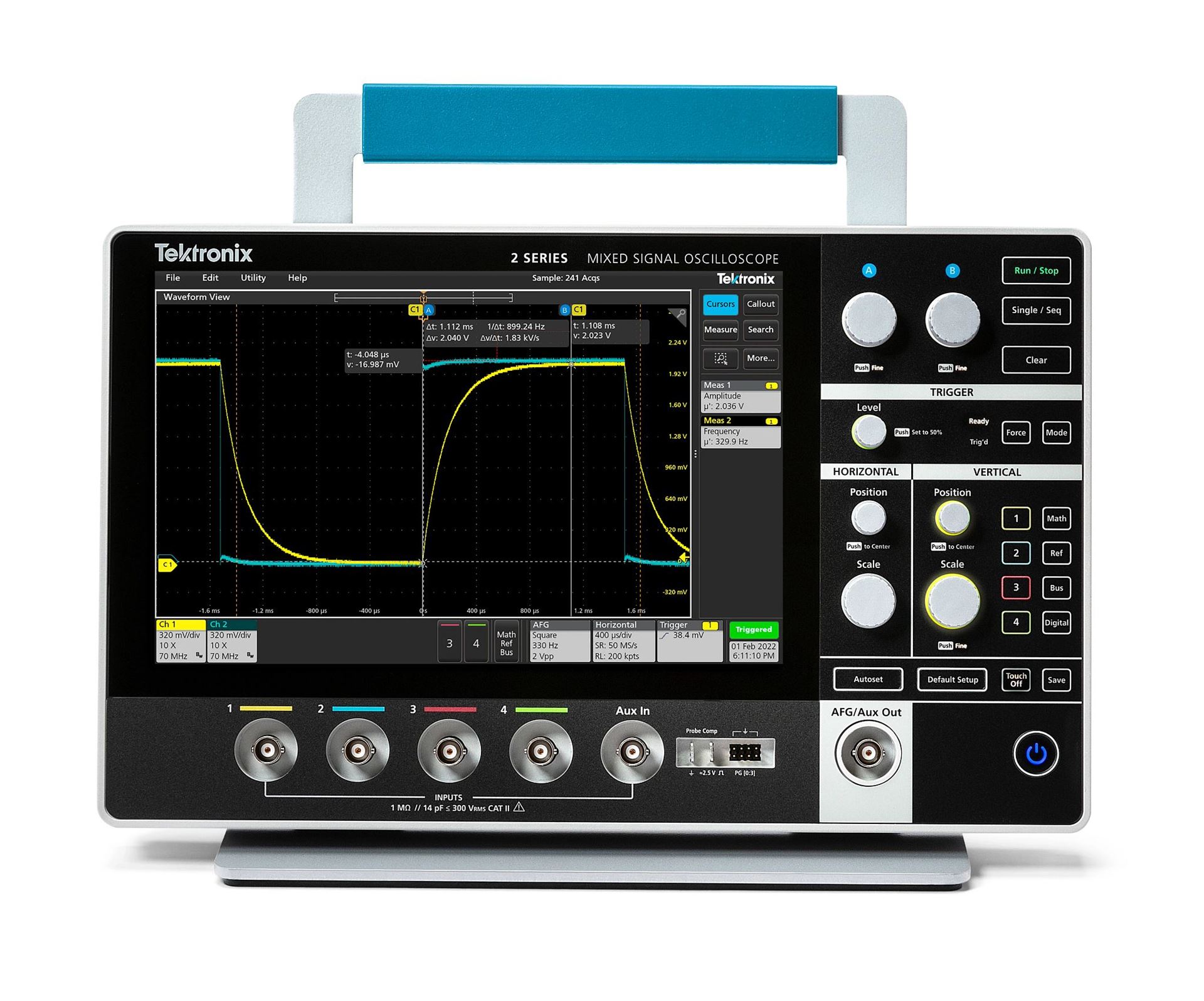
Ein Oszilloskop, früher auch als Oszillograph (umgangssprachlich Scope, Oscope oder O-Scope) bezeichnet, ist ein Tischinstrument, das elektrische Signale grafisch darstellt und zeigt, wie sich diese Signale im Laufe der Zeit verändern. Sie werden von Ingenieuren zur Fehlersuche in Schaltungen und zur Überprüfung der Signalqualität verwendet. Die meisten Ingenieure verwenden ein digitales Oszilloskop, worauf wir uns hier konzentrieren werden. Digitale Oszilloskope erfassen und speichern Wellenformen, die die Spannung eines Signals, die Frequenz, den Anteil des Rauschens am Signal, die Verzerrung des Signals, den zeitlichen Abstand zwischen den Signalen und vieles mehr anzeigen.
Grundlegende Parameter für die Auswahl eines Oszilloskops
Bandbreite des Oszilloskops
Die Bandbreite ist eine der wichtigsten Eigenschaften, die die höchste Frequenz bestimmt, die Ihr Oszilloskop genau messen kann. Sie ist ein wichtiger Faktor, der sowohl die Funktionalität als auch die Kosten des Oszilloskops beeinflusst.

Je höher die Bandbreite ist, desto genauer ist die Wiedergabe Ihres Signals, wie die Abbildung mit einem Signal zeigt, das mit einer Bandbreite von 250 MHz, 1 GHz und 4 GHz aufgezeichnet wurde.
Mehr über die Bandbreite erfahren
So können Sie Ihren Bandbreitenbedarf berechnen
Bei der Auswahl eines Oszilloskops empfiehlt es sich, die folgende Formel zu verwenden, um sicherzustellen, dass Sie die höchste Frequenzkomponente Ihres Signals abdecken:

Wenn Ihre höchste Signalfrequenz beispielsweise 20 MHz beträgt, sollten Sie ein Oszilloskop mit einer Bandbreite von mindestens 60 MHz wählen.
Oszilloskop-Anstiegszeit
Die Anstiegszeit ist für digitale Anwendungen von entscheidender Bedeutung, da sie die Fähigkeit des Oszilloskops angibt, schnelle Änderungen in einem Signal zu verfolgen.

Charakterisierung der Anstiegszeit eines digitalen Hochgeschwindigkeitssignals.
Mehr über die Anstiegszeit erfahren
Berechnen Sie die für Ihr Oszilloskop benötigte Anstiegszeit
Die Anstiegszeit des Oszilloskops sollte deutlich kürzer sein als die schnellste Anstiegszeit in Ihrem Signal. Verwenden Sie diese Formel, um ein geeignetes Oszilloskop zu finden:

Bei einem Signal mit einer Anstiegszeit von 4 ns sollte die Anstiegszeit des Oszilloskops weniger als 1,33 ns betragen.
Oszilloskop-Abtastrate
Die Abtastrate gibt an, wie häufig das Oszilloskop das Signal abtastet, welches einen Einfluss auf die Detailgenauigkeit der erfassten Wellenform hat.

Eine höhere Abtastrate sorgt für eine bessere Signalauflösung und stellt sicher, dass Sie intermittierende Ereignisse erkennen können.
Mehr über die Anstiegszeit erfahren
Bestimmen Sie die richtige Abtastrate für Ihr Oszilloskop
Für die Wahl einer angemessenen Abtastrate sollten Sie die folgende Richtlinie verwenden:

Für ein Signal mit einer maximalen Frequenz von 20 MHz sollten Sie ein Oszilloskop mit einer Abtastrate von mindestens 200 MS/s verwenden. Dies gewährleistet eine detaillierte Erfassung der Wellenform und erleichtert eine genaue Analyse.
Other Considerations for Oscilloscope Selection
Channel density of an oscilloscope
Digital oscilloscopes sample analog channels to store and display them. In general, the more channels the better, although adding channels adds to the oscilloscope price.

Your application will determine whether you need to choose an oscilloscope with two, four, six, or even eight analog channels. Two channels let you compare a component’s input to its output, for example. Four analog channels let you compare more signals and provides more flexibility to combine channels mathematically (multiplying to get power, or subtracting for differential signals, for example). Oscilloscopes with six or eight channels allows for multiple bus analysis while simultaneously viewing voltage or current type signals in a power related environment.
A Mixed Signal Oscilloscope adds digital timing channels, which indicate high or low states and can be displayed together as a bus waveform. Whatever you choose, all channels should have good range, linearity, gain accuracy, flatness, and resistance to static discharge.
Some instruments share the sampling system between channels to save money. But beware: the number of channels you turn on can reduce the sample rate.
Compatible oscilloscope probes
Good measurements begin at the probe tip. The scope and probe work together as a system, so be sure to consider probes when selecting an oscilloscope.
When taking measurements, probes actually become a part of the circuit, introducing resistive, capacitive, and inductive loading that alters the measurement. To minimize the effect, it’s best to use probes that are designed for use with your scope.
Select passive probes that have sufficient bandwidth. The probe’s bandwidth should match that of the oscilloscope.
A broad range of compatible probes will allow you to use your scope in more applications. Check to see what’s available for the scope before you buy.

Passive probes: Probes with 10X attenuation present a controlled impedance and capacitance to your circuit, and are suitable for most ground-referenced measurements. They are included with most oscilloscopes – you’ll need one for each input channel.
High-voltage differential probes: Differential probes allow a ground-referenced oscilloscope to take safe, accurate floating and differential measurements. Every lab should have at least one.
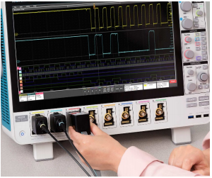
Logic probes: Logic probes deliver digital signals to the front end of a Mixed Signal Oscilloscope. They include “flying leads” with accessories designed to connect to small test points on a circuit board.
Current Probes: Adding a current probe enables the scope to measure current, of course, but it also enables it to calculate and display instantaneous power.
Need help choosing the right probe? See our Probe Selector Guide
Triggering capabilities of an oscilloscope
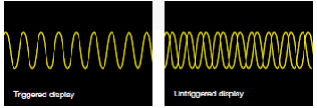
All oscilloscopes provide edge triggering, and most offer pulse width triggering. To acquire anomalies and make best use of the scope’s record length, look for a scope that offers advanced triggering on more challenging signals.

The wider the range of trigger options available the more versatile the scope (and the faster you get to the root cause of a problem):
- Digital/pulse triggers: pulse width, runt pulse, rise/fall time, setup-and-hold
- Logic triggering
- Serial data triggers: embedded system designs use both serial (I2C, SPI,CAN/ LIN…) and parallel buses.
- Video triggering
Oscilloscope record Length
Record length is the number of points in a complete waveform record. A scope can store only a limited number of samples so, in general, the greater the record length, the better.
Time captured = record length/sample rate. So, with a record length of 1 Mpoints and a sample rate of 250 MS/sec, the oscilloscope will capture 4 ms. Today’s scopes allow you to select the record length to optimize the level of detail needed for your application.
A good basic scope for example will store over 2,000 points, which is more than enough for a stable sine-wave signal (needing perhaps 500 points), whilst more advanced high-end scopes would have up to 1Gpoints, which is essential for working with high-speed serial data type applications.
Oscilloscope waveform capture rate
Waveform capture rate, expressed as waveforms per second (wfms/s), refers to how quickly an oscilloscope acquires waveforms. The waveform capture rates of oscilloscopes vary greatly, so it’s important to find the right one for your application.
Oscilloscopes with high waveform capture rates provide significantly more visual insight into signal behavior, and dramatically increase the probability that the oscilloscope will quickly capture transient anomalies such as jitter, runt pulses, glitches and transition errors.
Digital storage oscilloscopes (DSO) employ a serial processing architecture to capture from 10 to 5,000 wfms/s. Some DSOs provide a special mode that bursts multiple captures into long memory, temporarily delivering higher waveform capture rates followed by long processing dead times that reduce the probability of capturing rare, intermittent events.
Most digital phosphor oscilloscopes (DPO) employ a parallel processing architecture to deliver vastly greater waveform capture rates. Some DPOs can acquire millions of waveforms in just seconds, significantly increasing the probability of capturing intermittent and elusive events and allowing you to see the problems in your signal more quickly.
Oscilloscope expandability
As your needs change, you want an oscilloscope that can accommodate your needs with application modules and software updates.
If you want to expand the capabilities of your oscilloscope over time, make sure your instrument has everything you need. For instance, some oscilloscopes allow you to:
- Add memory to channels to analyze longer record lengths
- Add application-specific measurement capabilities
- Complement the power of the oscilloscope with a full range of probes and modules
- Work with popular third-party analysis and productivity
- Windows-compatible software
- Add accessories, such as battery packs and rack mounts
Connectivity of an oscilloscope
After you’ve analyzed your oscilloscope measurements, you’ll need to document and share your findings. The connectivity of an oscilloscope delivers advanced analysis capabilities and simplifies the documentation and sharing of results.
Depending on the oscilloscope, you may have access to standard interfaces (GPIB, RS-232, USB, and Ethernet), network communication modules, or advanced features that allow you to:
- Create, edit and share documents on the oscilloscope, all while working with the instrument in your particular environment
- Access network printing and file sharing resources
- Access the Windows® desktop
- Run third-party analysis and documentation software
- Link to networks
- Access the Internet
- Send and receive e-mail
Need help choosing an oscilloscope? Download our oscilloscope selector guide or contact the experts at Tektronix to request a demo. If you already have a sense of which oscilloscope to buy, shop Tektronix oscilloscopes today.


