Contact us
Live Chat with Tek representatives. Available 6:00 AM - 4:30 PM
Call us at
Available 6:00 AM – 5:00 PM (PST) Business Days
Download
Download Manuals, Datasheets, Software and more:
Feedback
Ethernet SFP+ QSFP+ Tx Compliance & Debug Solution
SFP-TX, SFP-WDP Datasheet
More Information
- Máy hiện sóng lân quang số/tín hiệu hỗn hợp MSO/DPO70000DX
- Máy hiện sóng hiệu suất DPO70000SX ATI
- Explore more Software models
Read Online:

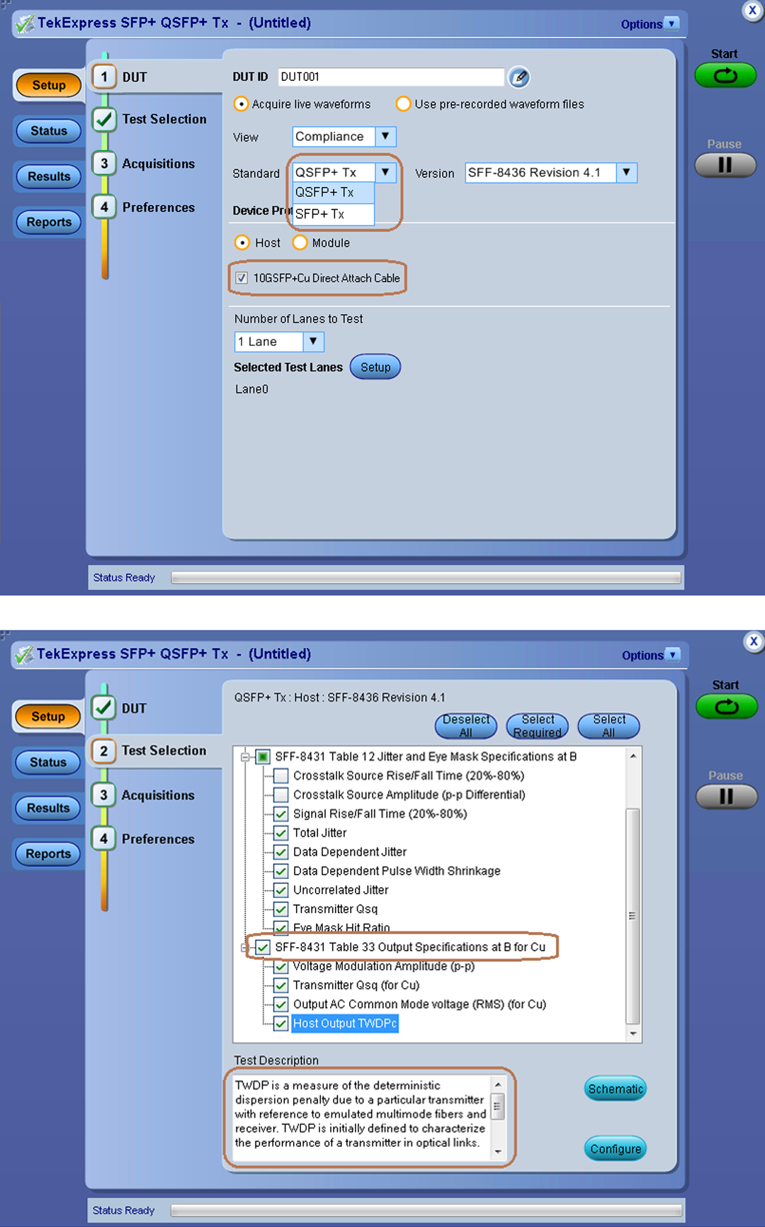
TekExpress SFP-TX user interface for PHY measurements including SFP+ Direct Attach Cable Specifications “10GSFP+CU and QSFP+ specification”.
Features and benefits
- Tektronix SFP+ QSFP+ Tx Automated Compliance and Debug Solution (SFP-TX and SFP-WDP option) meets the compliance and debug needs of design and test engineers working on SFF-8431 & SFF-8635 Designs.
- Tektronix SFP+ QSFP+ Tx is developed on a real time oscilloscope platform, which is the platform of choice for engineers working on designing their products around SFF-8431 & SFF-8635 technology.
- Option SFP-TX and SFP-WDP enable both an automation solution (for compliance) and DPOJET Option (for debug). Users can save up to 80% on testing time as compared to manual testing.
- TWDPc – Transmitter Waveform Distortion Penalty for Copper measurements are available to customers with Option SFP-WDP. SFF-8431 SFP+ TWDPc based Matlab code has been integrated into the SFP-WDP option to make sure engineers can use this measurement in the automated setup.
- Design engineers can seamlessly move from compliance to debug environment and use world-class debug tool from Tektronix (such as, DPOJET).
- User-defined mode enables flexible parameter control for characterization and margin analysis.
- User defined mode supports PRBS7, PRBS11, PRBS15, PRBS20 & PRBS23 in addition to patterns supported in compliance mode including PRBS9, PRBS31 and 8180.
- Tektronix application supports multiple data rates including 9.95328 Gbps, 10.3125 Gbps, 10.51875 Gbps and 11.10 Gbps.
- Complete programmatic interface available; users can call SFP-TX functions using their automation scripts.
- SFP-TX Compliance solution performs automatic signal validation before performing tests and throws an error if the signal does not meet acceptable limits.
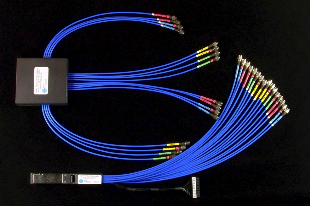
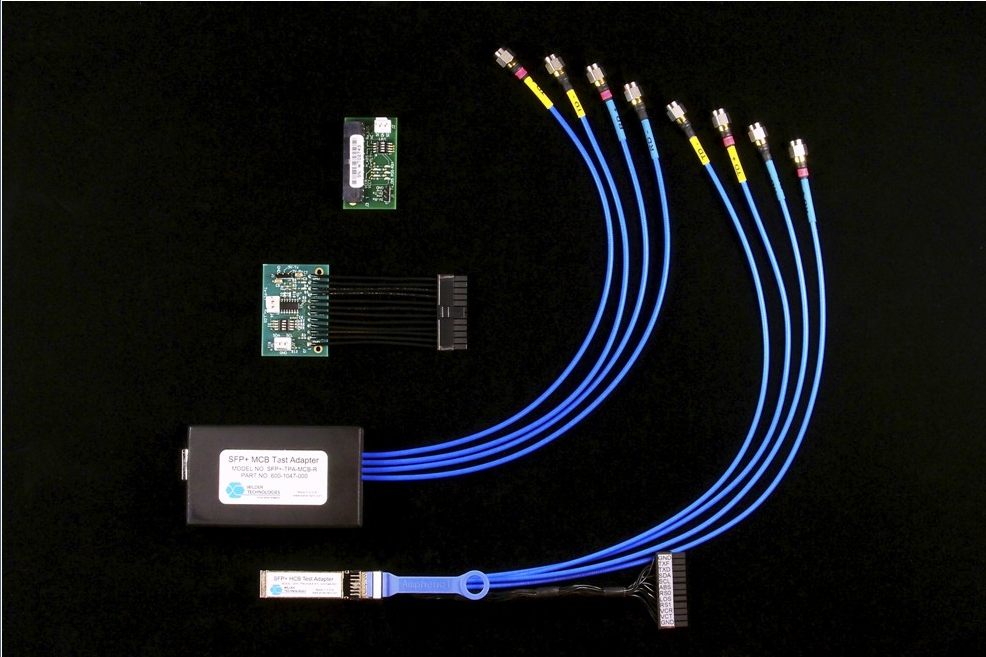
- Signal acquisition and analysis support available using cost-effective SMA cables.
- DPOJET setup files for N1N0, PRBS11 and PRBS31 patterns are provided with the SFP-TX which help set oscilloscope and load measurements in DPOJET. This helps reduce debug time and set the oscilloscope for debug environment.
- New intuitive user Interface and framework decreases testing time and learning curve for end users.
- Measurements are grouped on signal types best suited for the measurement, which reduces user intervention.
- End-users can receive e-mail notification on measurement results and stay connected with their test setup.
- Design engineers can use many built-in reporting features such as, appending the report, auto-incrementing the report, and including user comments to tailor their reporting requirements.
- Provides customers with a Tektronix floating license installation option.
- Detailed test reports with margin and statistical information aid analysis.
Applications
Ethernet SFP+/QSFP+ PHY transmitter and direct attach cable testing for:
- Device Silicon Validation
- Cable and Connector Validation
- System Compliance and Debug
- Manufacturing Test
TekExpress SFP-TX measurement setup
The SFP-TX solution helps customers to easily select measurements for SFF-8431 (SFP+ Tx) & SFF-8635 (QSFP+ Tx) testing. Simple and easy-to-use measurement setup helps customers perform all measurements with a single button click. Automation options help customers meet compliance needs and generate detailed reports. User-defined mode lets customers make changes to the test limits and perform margin testing beyond compliance.

DPOJet SFP-TX measurement setup
The SFP-TX solution helps customers to easily select measurements for SFF-8431 (SFP+ Tx) & SFF-8635 (QSFP+ Tx) testing. All masks, limits, and measurement parameters are automatically configured for the customer. Additionally, customers have the flexibility to change selected measurements and measurement configurations within DPOJET. SFP-TX DPOJET options provide a new standard-specific UI.

Seven new additional measurements have been added including VMA, Rise Time, Tx-Qsq, DDPWS, Fall Time, UJ, and TWDPc which were not part of the original DPOJET package. Setup files are provided based on different signal types such as 8180, PRBS9, and PRBS31. Signal-specific setup files allow design engineers to perform measurements on different signal types, letting them go into Analysis and Debug mode.
Simplified instrument setup - Save time and resources
Setup and test execution is simple with the SFP-TX software. The oscilloscope acquisition and analysis are all controlled through the SFP-TX automation solution. The software’s Graphical User Interface (GUI) provides an intuitive workflow for setup and testing.
Margin testing
Design characterization is supported beyond SFF-8431 (SFP+ Tx) & SFF-8635 (QSFP+ Tx) compliance requirements for all measurements. Qualify PHY with flexible control over test configurations such as analysis windows and other parameters. User-defined mode lets customers make changes to the test limits and perform marginal testing beyond compliance.

TWDPc - Transmitter Waveform Distortion Penalty for Copper
SFF-8431 SFP+ suggests that this measurement should be performed on SFP+ Host Transmitter Output Specifications at B for Cu.


Customers who plan to use TWDPc measurements need to purchase Option SFP-WDP. TWDPc is a measure of the deterministic dispersion penalty due to a particular transmitter with reference to the emulated multi-mode fibers and a well-characterized receiver. TWDPc is initially defined to characterize the performance of a transmitter in optical links. The same concept has been extended to quantify channel performance as well, especially in high-speed copper links. SFF-8431 Revision 4.1 Table 33 – Host Transmitter Output Specifications at point B for Cu.
For TWDPc compliance, a simulated cable response is required. The response is modeled as a set of delta functions with specific amplitudes and delays. The copper stressor was created from measurements of commonly available direct attach SFP+ cables with the transmitter response de-convolved. The stressor is shown in the following figure and the values are listed in Table 34 of the SFF-8431 SFP+ specification. The sum of all stressor components is normalized to an approximate value of 1.

TWDPc measurements are supported only on C and D Series real-time oscilloscopes with a sampling rate of 100 GS/s and ≥16 GHz bandwidth due to the following:
- The TWDPc script (of 802.3aq, 10GBASE-LRM) processes a PRBS9 pattern requiring at least 16 samples per unit interval.
- Out of concern for the large installed base of sampling oscilloscopes with a record length of around 4000 samples the requirement for 16 samples per unit interval is relaxed to 7 samples per unit interval.
- The relaxation of the requirement for 16 samples per unit interval to just 7 samples per unit interval causes worst-case 0.24 dB TWDPc pessimism over 30 measurements. For DUTs that already have a high WDP, 0.24 dB can be the difference between a Pass or Fail result.
- With a DPO/DSA/MSO70000C/D/DX/SX Series oscilloscope, a 100 GS/s sampling rate is available. Around 10 samples per UI will be obtained from the hardware.
Tektronix recommends to only run TWDPc measurements on DPO/DSA/MSO70000C/D/DX/SX Series oscilloscopes.
SFP module measurements
SFP-TX supports 10 new measurements for the SFP+ module. These include AC Common Mode Voltage Tolerance, Single-ended Input Voltage Tolerance, Crosstalk Source Rise/Fall Time (20-80%), Crosstalk Source Amplitude (P-P Differential), Output AC Common Mode Voltage (RMS), Total Jitter, Data Dependent Jitter, Data Dependent Pulse Width Shrinkage, Uncorrelated Jitter, and Eye Mask Hit Ratio.

SFP total jitter measurements
SFP-TX allows users to enter BER value of in the range of BER e^–2 to –18, providing them the flexibility to calculate Total Jitter at various BER values.

J2 and J9 (under QSFP+ dropdown menu) measurements have been added as informative measurements to SFP-TX, these measurements are part of other 10G standards like 40GBASE-CR4 and XLPPI.

De-embedding feature
As data rates increase, high-speed serial technologies have introduced new test methodologies and requirements for compliance testing. As technologies such as SFP+ increase in data rates, the eye is closed and different components such as SMA cables can be de-embedded to get better results. SFP-TX provides an option to de-embed the signal using .FLT files.

Report Configuration menu
The Report Configuration menu lets users configure reports, and it provides options such as auto increment and appending.

One-button testing
Once the test bench is set up and the DUT is properly connected, press the Run button to perform the selected test suite. The SFP-TX solution prompts the end-user to put the DUT into different test modes by displaying messages at regular intervals.

Automation support
Save and recall setup files in automation script, with an option to automate the complete test bench. Tektronix end-users can call the SFP-TX application programmatically through NI LabVIEW, NI TestStand™, or any other scripting language for controlling SFP-TX along with other instrumentation such as thermal chambers and power supplies.

Multiple data rate support
Tektronix application supports multiple speeds. Many products available in market support multiple data rates including 9.95328Gbps, 10.3125 Gbps, 10.51875 Gbps and 11.10 Gbps.

Multiple pattern support
Tektronix application supports multiple patterns in user defined mode. Various products available in market support patterns over and above what is specified in SFF-8431 and SFF-8635. User defined mode supports PRBS7, PRBS11, PRBS15,PRBS20 & PRBS23 in addition to patterns supported in Compliance mode including PRBS9, PRBS31 and 8180.

Pass/Fail report
A summary report in .MHT (MHTML) format with Pass/Fail status is automatically generated after tests complete. The report includes test configuration details, waveform plots, and margin analysis to provide more insight into your design.

Specifications
SFF-8431 (SFP+) & SFF-8635 (QSFP+) measurements covered in SFP-TX/SFP-WDP solution
| SL No. | Measurements | Recommended signal type | Limit | |||
|---|---|---|---|---|---|---|
| Min. | Target | Max | Units | |||
| Host transmitter output electrical specifications | ||||||
| 1 | Single-ended Output Voltage Range | PRBS31 | –0.3 | 4 | V | |
| 2 | Output AC Common Mode Voltage (RMS) | PRBS31 | 15 | mV (RMS) | ||
| Host transmitter jitter and eye mask specifications | ||||||
| 3 | Crosstalk Source Rise/Fall Time (20%-80%) (Tr, Tf) | 8180 | 34 | ps | ||
| 4 | Crosstalk Source Amplitude (p-p differential) | 8180 | 1000 | mV | ||
| 5 | Signal Rise/Fall Time (20%-80%) (Tr, Tf) | 8180 | 34 | ps | ||
| 6 | Total Jitter (p-p) (Tj) | PRBS31 | 0.28 | UI (p-p) | ||
| 7 | Data Dependent Jitter (p-p) (DDJ) | PRBS9 | 0.1 | UI (p-p) | ||
| 8 | Data Dependent Pulse Width Shrinkage (p-p) (DDPWS) | PRBS9 | 0.055 | UI (p-p) | ||
| 9 | Uncorrelated Jitter (RMS) (UJ) | PRBS9 | 0.023 | UI (p-p) | ||
| 10 | Transmitter Qsq | 8180 | 50 | |||
| 11 | Eye Mask Hit Ratio (Mask hit ratio of 5×10⁻⁵) | PRBS31 | X1 = 0.12 UI, X2 = 0.33 UI, Y1 = 95 mV, Y2 = 350 mV | |||
| Host Transmitter Output Specifications for Cu (SFP+ host supporting direct-attach cables) | ||||||
| 12 | Voltage Modulation Amplitude (p-p) | 8180 | 300 | mV | ||
| 13 | Transmitter Qsq Output AC Common Mode Voltage | 8180 | 63.1 | |||
| 14 | Output AC Common Mode Voltage | PRBS31 | 12 | mV (RMS) | ||
| 15 | Host Output TWDPc | PRBS9 | 10.7 | dBe | ||
Ordering information
SFP-TX SFP-WDP
SFF-8431 (SFP+ Tx) & SFF-8635 (QSFP+ Tx) compliance and debug solution.


To order along with oscilloscope
| Oscilloscope | Option |
|---|---|
| SFP-TX | |
| DPO/DSA/MSO70000C/D/DX/SX | Order SFP-TX |
| SFP-WDP | |
| DPO/DSA/MSO70000C/D/DX/SX | Order SFP-WDP |
To upgrade an existing oscilloscope
| Oscilloscope | Option |
|---|---|
| SFP-TX | |
| DPO/DSA/MSO70000C/D/DX/SX | Order DPO-UP SFP-TX |
| DPO/DSA/MSO70000C/D/DX/SX | Order DPOFL-SFP-TX (Floating License) |
| DPO/DSA/MSO70000C/D/DX/SX | Order DPOFT-SFP-TX (Floating Trial) |
| SFP-WDP | |
| DPO/DSA/MSO70000C/D/DX/SX | Order DPO-UP SFP-WDP |
| DPO/DSA/MSO70000C/D/DX/SX | Order DPOFL-SFP-WDP (Floating License) |
| DPO/DSA/MSO70000C/D/DX/SX | Order DPOFT-SFP-WDP (Floating Trial) |
Recommended equipment
| Oscilloscope | Required software | Required accessories | Test fixture |
|---|---|---|---|
| DPO/DSA/ MSO71604C | SFP-TX, DJA 1 SFP-WDP 23 | Matched-pair SMA Cables (TCA-SMA connector) | TF-SFP-TPA-HCB-PK – Host Compliance Board OR TF-QSFP-TPA-HCB-P QSFP+ Host Compliance Board Plug |
| DPO/DSA/ MSO72004C | |||
| DPO/DSA72504D | |||
| DPO/DSA73304D |
Recommended oscilloscopes for SFF-8431 (SFP+ Tx) & SFF-8635 (QSFP+ Tx) PHY testing
DPO/DSA/MSO71604C
DPO/DSA/MSO72004C
DPO/DSA72504D
DPO/DSA73304D

- Tektronix is ISO 14001:2015 and ISO 9001:2015 certified by DEKRA.

- Product(s) complies with IEEE Standard 488.1-1987, RS-232-C, and with Tektronix Standard Codes and Formats.

Bluetooth is a registered trademark of Bluetooth SIG, Inc.

LTE is a trademark of ETSI.


