Whether positive or negative, your feedback helps us continually improve the Tek.com experience. Let us know if you're having trouble or if we're doing an outstanding job.
DPO70000SX provides ultra-high bandwidth real time signal acquisition and analysis up to 70 GHz analog bandwidth. The patented Asynchronous Time Interleaving (ATI) architecture provides the lowest noise and highest fidelity for real time signal acquisition.
Superior signal fidelity and excellent signal-to-noise ratio
Stable and precise multi-channel timing for most accurate analysis
Compact instrument package with flexibility for future expansion and simple reconfiguration
Introduction
DPO70000SX Series oscilloscopes provide the most accurate real time performance for ultra-bandwidth applications.
Low noise, 70 GHz real time signal capture using patented ATI architecture
Compact 5 ¼" (3U) instrument package for the most versatile multi-channel systems
Precise, scalable performance using UltraSync multi-unit time synchronization bus
14.1 Gbps hardware serial trigger - Assures triggering on the first instance of a specified 8b/10b, 64b/66b, or generic NRZ pattern to allow isolation of pattern-dependent effects
Bit error detector - Implemented within the trigger system, this feature provides simple bit error measurement against a defined pattern file, with no missed bits
Low noise, high fidelity signal acquisition is critical in ultra-bandwidth applications such as long-haul coherent optical, 400G datacom and wideband RF. The flagship DPO77002SX model uses ATI (Asynchronous Time Interleaving) architecture to achieve 70 GHz and 200 GS/s (5 ps/Sample) real time acquisition performance. This patented, symmetric architecture elegantly creates an inherent noise advantage over legacy bandwidth interleaving methods. The DPO70000SX provides the lowest noise, highest fidelity and maximum performance for complex optical modulation analysis, jitter and noise analysis of high speed serial signaling and frequency, phase and modulation analysis of wideband RF signals.
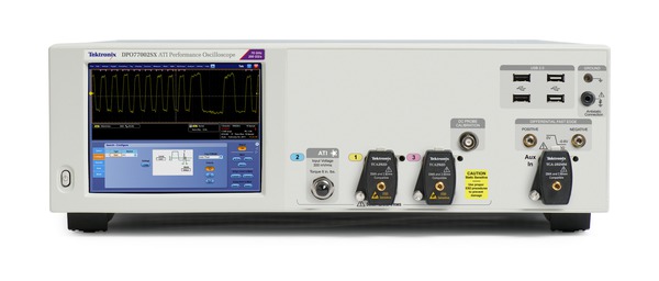
DPO70000SX ATI Performance Oscilloscopes
70 GHz, 59 GHz, or 50 GHz analog bandwidth
Low-noise ATI architecture
200 GS/s, 5ps/Sample real-time sample rate
DPO70000SX TekConnect Performance Oscilloscope
33, 25, 23, 20, 16, or 13 GHz analog bandwidth
100 GS/s, 10 ps/Sample real-time sample rate
Bandwidth upgradable to ATI 70 GHz, 59 GHz, 50 GHz models
Applications
Coherent optical modulation analysis
Research and defense data acquisition and analysis
100G/400G datacom system debug
PCIe debugging and compliance testing
High-speed serial communications debugging and compliance testing
PCIe, USB, Thunderbolt, HDMI, DisplayPort, and more
Previous real time scope solutions for digitizing ultra-high bandwidth signals distribute signal energy to two digitizing paths, and then use DSP to reconstruct the input signal. Unlike legacy schemes, Tektronix' unique ATI architecture provides a symmetric technique that delivers all signal energy to both digitizing paths resulting in an inherent noise advantage.
The diagram shows how an input signal enters the ATI ASIC where it is sampled and alternately delivered to each digitizing subsystem. The sample clock runs at 75 GHz and effectively folds the spectrum of the input signal about 37.5 GHz prior to digitizing. Each digitizing path operates at 100 GS/s and the folded spectrum is band limited to <40 GHz to meet Nyquist criteria. The alternating phase of the sampler has the effect of inverting signal phase 180° in one digitizing path, which provides significant benefit in reconstructing the final digitized signal.
With two copies of the entire signal energy digitized, the signal spectra are "unfolded" using a DSP equivalent of the sampling process and combined to reproduce the input signal. Because two copies of the signal are being combined the process effectively averages them together, reducing random noise. Phase-inversion introduced by the sampling process causes intermediate frequency components to directly cancel one another, simplifying reconstruction and calibration.
Thus, ATI architecture provides an inherent SNR advantage over legacy digital-bandwidth interleaving techniques. These techniques immediately split an input signal into upper and lower bands of frequencies. This divides the power and the upper frequency band must be mixed down prior to digitizing while the lower band is directly digitized. This asymmetric approach can make signal reconstruction and calibration more difficult and lead to errors in pass-band frequency or phase response. The division of power removes the opportunity to reduce signal noise. ATI alleviates these issues by using a unique symmetric architecture.
A comparison of baseline noise between the Tektronix DPO77002SX and another vendor's 63 GHz model, with both instruments set to 60 GHz bandwidth, demonstrates the effectiveness of ATI at providing the lowest noise acquisition.
DPO77002SX vs. other vendor's 63 GHz model: Baseline noise % of FS vs. mVFS setting, with trace centered, at 60 GHz BW, maximum sample rate setting (200 GS/s or 160 GS/s)
JNF performance
An all-new master sample clock design which provides the remarkably low sample clock jitter of 65fsRMS, combined with the very low noise performance achieved with ATI, allows the DPO77002SX to reach new levels of jitter noise floor performance. The JNF at 300 mVFS is a mere 123 fsRMS, which even rivals lower bandwidth instruments.
The figure shows jitter analysis of 60 GHz sine wave applied to the ATI input. The result shows a clean eye with random jitter RJ <80 fsRMS.
DPO70000SX Series models establish a unique compact oscilloscope package that enables unprecedented workspace efficiency and mounting versatility. The SX series provides a differentiated approach to ultra-bandwidth real time acquisition that aligns with user trends toward large external monitors, higher degrees of automation and increased separation of data collection and data analysis workspaces.
Stand-alone DPO70000SX compact models provide functionality equivalent to their bench counterparts (DPO70000DX) at half the height through addition of external display, keyboard and mouse. SX series models can host Advanced Analysis software and be automated using internal or external control just as their bench counterparts.
The DPO77002SX 70 GHz ATI Performance Oscilloscope provides one channel at 70 GHz, 200 GS/s acquisition performance or two channels at 33 GHz, 100 GS/s acquisition. The instrument includes a 70 GHz, 1.85 mm low-noise ATI input channel as well as general purpose TekConnect 2.92 mm inputs for versatile probing and signal conditioning options to 33 GHz.
The DPO73304SX model provides two channels at 33 GHz, 100 GS/s acquisition or four channels at 23 GHz, 50 GS/s real time acquisition performance. This model provides acquisition performance similar to the DPO73304DX bench model, but in the new compact instrument form-factor.
All models in the DPO70000SX Series achieve the highest level of trigger performance available in real time oscilloscopes, >25 GHz edge trigger performance and <40 ps glitch trigger performance. An innovative new Window trigger type enables triggering on the envelope of RF signal bursts with time-qualification to discriminate envelope width. Industry-leading pulse-width timer performance enables the most precise discrimination of specific bit-widths in high speed serial data streams and detection of "runt" pulses in the midst of pseudo-random signaling. The DPO70000SX Series Auxiliary Trigger input provides low-jitter edge triggering and uses TekConnect accessories for a wide variety of signal conditioning solutions.
Optimal usability
Less than half the height of bench models
DPO70000SX Series instruments are contained in a 5 ¼" (3U) package that optimizes space usage and enables the most versatile range of mounting configurations. Two DPO70000SX instruments stack in less height than similar-class bench instruments, yet achieve higher measurement performance.
Complete standalone oscilloscope
Though compact, SX models provide full standalone oscilloscope functionality and performance. They can directly host Tektronix' Advanced Analysis applications for tasks such as jitter, noise, optical modulation or spectral analysis and do not require a separate processor or control unit.
2 x 70 GHz, 4 x 33 GHz configuration with monitor and auxiliary front panel
Familiar scope controls where you want them
The DPO7AFP Auxiliary Front Panel is a valuable usability accessory that compliments the compact instrument package by enabling users to operate with familiar controls without requiring access to the front of an instrument.
The Auxiliary Front Panel provides the same control set embedded in DPO/DSA/MSO/7000/70000 bench instruments as a separately packaged USB peripheral. This accessory enhances usability even when the instrument front panel may be obscured due to mounting location.
Remote desktop operation
As with current bench-model DPO/MSO70000 Series instruments, DPO70000SX models can be operated remotely over a network using Windows® Remote Desktop. Use the Windows Remote Desktop utility to access your oscilloscope from across the lab or across the globe.
Precision synchronization for multi-unit systems
DPO70000SX Series instruments include the Tektronix UltraSync multi-unit time synchronization bus. UltraSync is used to synchronize sample clock, trigger and run-stop control across multiple units with performance equivalent to that found in monolithic scopes. UltraSync cables are available in 1 meter and 2 meter length to maximize configuration and layout versatility while preserving timing integrity of a multi-unit system.
The UltraSync bus consists of three elements, each providing an important element of precise multi-unit operation:
UltraSync includes a 12.5 GHz Sample Clock Reference signal sourced by the Master and used by each Extension to synchronize sample placement in the digitizing process.
The Trigger bus provides Run-Stop control for all members of a multi-unit configuration and enables the trigger source to be from a Master or Extension unit.
Control & data transfer from Extension units to the Master are managed with a PCIe, Gen 2, x4 link capable of 2 GB/s data transfer rate.
When operating in a multi-unit instrument configuration, one DPO70000SX has the role of Master, controlling one or more units operating in Extension mode. Any DPO70000SX model can operate as a standalone oscilloscope or serve as Master or Extension in a multi-unit configuration. Roles are determined by UltraSync cabling and no additional elements are needed. This allows users to decouple multi-unit configurations at any time and operate instruments in a standalone fashion without requiring a control unit or other accessories. Or, standalone units can be easily combined by simply adding UltraSync cables between Master and Extension.
During startup of a multi-unit configuration a Configuration Manager application validates Master-Extension cabling and provides graphical feedback if elements are missing or misconfigured. Following validation, the system presents the TekScope user interface where waveforms from Master and Extension units are gathered for display and analysis using built-in features and Advanced Analysis applications.
Scalable performance and versatile configurations
DPO70000SX multi-unit modes enable a variety of extended performance and increased channel-count configurations. Master-Extension configurations provide additional input channels synchronized to the same degree of precision as internal channels and controlled from a single user interface as an interactive instrument or programming interface in automated applications.
This scalable approach to performance allows users to purchase performance suitable for today's requirements, such as four channels of 33 GHz, 100 GS/s acquisition while also having two channels with 70 GHz, 200 GS/s performance suitable for next-generation designs. Subsequently, two additional units can be added for a total of four channels at 70 GHz, 200 GS/s. Units in this four-unit configuration can be separately deployed as pairs or standalone units at any time to meet other test demands.
The DPO77002SX also offers a unique value proposition in single-channel 70 GHz, 200 GS/s applications such as RF analysis or pulsed laser studies. In these cases a user can purchase a single unit for 70 GHz channel performance along with two channels at 33 GHz. Additional units can be purchased at a later time and combined using UltraSync if higher channel count is needed.
The following multi-unit configurations are supported:
UltraSync provides outstanding integration and time alignment between units in a multi-unit stack. Once channels have been deskewed in a multi-unit stack, skew is very stable over time and temperature. The specification for skew stability is ≤250 fsRMS. The following DPO77002SX skew measurement plot shows that even when including the startup temperature stabilization period (approximately 1 hour), the pk-pk variation is about 400 fs, and is about 350 fs pk-pk after the 1-hour warm-up period. This plot also shows exceptional consistency over this 12-hour data collection.
Change in channel-to-channel skew of DPO77002SX system over time.
Another important aspect of skew is how the phase relationship between two channels varies with changing frequency (group delay effects). The following plot compares the performance of a DPS77004SX 70 GHz two-unit system against the performance of another vendor's 63 GHz frequency-interleaved channels. What you see here is that the UltraSync two-channel skew performance dramatically surpasses the performance of another vendor's single 63 GHz model containing two channels.
Channel skew vs. Frequency comparison between DPO77002SX system and other vendor's 63 GHz model.
Short signal path
Minimizing input signal path length is especially important when working at 70 GHz ultra-high bandwidth. The compact nature of DPO70000SX creates more versatile mounting options when co-locating instrument and device under test (DUT). Options such as the Auxiliary Front Panel and Remote Desktop connection allow further flexibility by eliminating the need for direct access to the instrument front panel once connected. As a result, the SX series enables the broadest range of options when dealing with a variety of DUT configurations as compared to classic bench instruments.
Input signal path length may be minimized in multi-unit configurations by inverting one unit of a pair. The low, central location of the 70 GHz ATI input provides very small input connector spacing when operating units in this configuration.
Instruments can also be arranged at various angles to suit DUT layout, such as at right angles for card-and-backplane situation or face-to-face around a small DUT. Layouts such as this create the shortest input signal path and maximize SNR. In addition, effects of signal path elements such as cables and adapters can be characterized and removed using the Serial Data Link Analysis application to obtain the best analysis results and insight.
Applications
High-Speed Serial
PCI Express® Transmitter Compliance and Debug (Options PCE3, PCE4, PCE5, PCE6) – Analyze the performance of your PCI Express® Rev 1.0, 2.0, 3.0, 4.0, 5.0, or 6.0 design with comprehensive test support. Using DPOJET and PAMJET Options PCE3, PCE4, PCE5 and PCE6 enables tests that conform to PCI-SIG standards.TekExpress® USB4 Automated Test Software (Option USB4) - The TekExpress® USB4 Compliance and Debug solutions provide an easy way to validate and characterize the emerging USB4 Router-Host, USB4 Router-Device, and USB4 Hubs as per the USB4 Electrical Compliance Test Specification (CTS). Tektronix MSO/DPO70000DX and DPO70000SX Series Oscilloscope (bandwidth ≥ 23 GHz) supports the Tektronix USB4 Compliance and Debug solutions.
Datacom measurements
PAM4 and NRZ measurements
The throughput of Datacom networks continues to increase. Tek's DPO70000SX is ready to perform standards validation for today's 25/28G industry standards and beyond (see chart below). The powerful combination of DPO70000SX, DPOJET Jitter and Noise Analysis, and the SDLA Serial Data Link Analysis tool performs accurate de-embedding and eye diagram analysis for these key Datacom standards. The 50 GHz to 70 GHz models provide ample bandwidth for Bessel-Thomson filter responses.
Datacom standards
Recommended bandwidth
Tektronix scope model
Ethernet
10GBASE KRn
100GBASE KR-4, CR-4
25 Gb Phy KR, CR for 100G
25 GHz
59 GHz
59 GHz
DPO72504DX
DPS75904SX
DPS75904SX
Fibre Channel
16Gb
32Gb
30 GHz
45 GHz
DPS75004SX
DPS75004SX
Infiniband
EDR 25Gb
50 GHz
DPS75004SX
OIF-CEI 3.0
CEI-25G
70 GHz
DPS77004SX
OIF-CEI 3.1
CEI-56G (PAM4)
CEI-56G (NRZ)
70 GHz
70 GHz
DPS77004SX
DPS77004SX
With 400G networking, serial data transmission speeds are now reaching 56 Gb/s per channel, making NRZ signaling techniques less practical. The bandwidth efficient PAM4 (4-level pulse amplitude modulation) signaling is being widely used to achieve this new performance level. Accurate PAM4 validation is best conducted using the DPO70000SX Series, with its industry-leading low-noise ATI technology, to achieve the best test margin on your measurement results. For analysis of PAM4, the DPO70000SX Options PAMJET-E and PAMJET-O combine industry leading equalization tools and a robust built-in software based clock recovery, which is essential to recovering complex timing and performing analysis of high ISI PAM4 signals.
Option PAMJET-E offers electrical measurements and option PAMJET-O offers optical measurements. Both comply with IEEE and OIF specifications. Optical interfacing is provided through the use of the DPO7OE Series optical probes, which include ORR filters.
IEEE 802.3bj (KR4/CR4) and IEEE 802.3bm (CAUI4) Electrical Real Time Transmitter Compliance and Characterization Solution (option 100G-TXE) - TekExpress 100G-TXE automation provides turnkey testing and debug of 100G Ethernet's three most common electrical interfaces. Tools for 100G- KR4/CR4/CAUI4 are brought together in a single 100G-TXE option to support silicon designers and system designers as they perform KR4 and CR4 validation.
Bit error detection
The bit error detector (option BITERR) is a generic simple NRZ bit error detector for serial data testing, covering data rates between 600 Mbps and 14.1 Gbps. It detects bit errors on a repeating pattern being sent by a serial transmitter. This feature utilizes the trigger system hardware, rather than waveform acquisition, so every bit is detected and verified; there are no blind periods or missed bits during bit error analysis. A pattern match file is used to define the expected incoming pattern. PRBS patterns are predefined, but users can also create their own unique pattern match files. Note that this optional feature is not protocol aware, and does not detect frame/symbol/character errors. When a bit error is detected, the oscilloscope triggers a waveform acquisition, resulting in a capture of the waveform containing the bit error. If the oscilloscope also has an optional serial decoder for the serial data stream being tested (for example, 8b10b), the acquired waveform can include decoded data, making analysis and debug of the error easier. Requires option ST14G.
Bit Error Detector (option BITERR) - Provides statistics on bits counted and number of errors detected, as well as displaying waveform data upon detection of a bit error. As shown here, the Bit Error Detector can be combined with optional serial data decoders to facilitate debug and diagnosis of errors.
Link Training
High Speed Serial Link Training Analysis - option HSSLTA - is a tool for verifying and debugging link training operation on 10 Gb through 200 Gb Ethernet links. It offers a powerful debugging capability for network equipment providers and silicon vendors concerned about interoperability issues in their designs. Link training is a complex sequence of negotiations between transmitter and receiver to determine optimal transceiver settings. HSSLTA uses the power of DPO70000SX triggering to identify link training exchanges between devices, then analyzes and displays the protocol, timing, and PHY signaling associated with link negotiation. This insight allows designers to verify the link training process and to quickly pinpoint problems when links fail to train.
The Most Efficient way to isolate link training issues:
Real time capture of PHY-layer signaling provides detailed insight
Control channel filtering stores essential conversation and removes redundant copies so only significant elements seen
Time-stamped control channel elements provide further insight into link training process
Linkage to PHY signaling provides quick navigation for exploring
Link Training (option HSSLTA) - Offers an interactive Results Table based on FastFrame records. - Fast-Frame Records: Time-aligned Hex and Bit-level decode, Marks (Frame, Control Channel, and Training Data). Results Table: All negotiation data is captured in Results Table, Click row to view waveform, Scroll through table rows, Verify Negotiation Requests/Responses, and Export Negotiation Data.
Compliance software
TekExpress® PCI Express Gen 1/2/3/4/5/6 Automated Test Software (Options PCE3, PCE4, PCE5, PCE6) - Provides the most comprehensive solution for PCI Express transmitter compliance testing from legacy Gen1 to most recent Gen6 BASE (as of Oct 2022). Covering troubleshooting and validation of PCI Express devices corresponding to the PCI-SIG specifications. The application automates selection of appropriate fixture de-embed, reference channel emulation filters, and measurement selections based on test type, device data rate, transmitter equalization, link width, and selected probes. TekExpress includes compliance automation solution that integrates the PCI-SIG's Sigtest test software with Tektronix DPOJET-based PCI Express Jitter and Eye Diagram, SDLA Serial Data Link Analysis Visualizer analysis tools for debug, as well as PAMJET for Gen6 PAM-4 modulation analysis. Results are presented in a comprehensive HTML format for engineering test documentation.Ethernet Compliance Test Solution (Option CMENET3) – Receive full PHY layer support for Ethernet variants 10BASE-T, 100BASE-TX, and 1000BASE-T with the comprehensive, integrated Tektronix® Ethernet tool set. Analog verification, automated compliance software, and device characterization solutions are all included.TekExpress Ethernet Tx (Options NBASET, XGBT2) - Automates 10GBASE-T, NBASE-T, and IEEE802.3bz (2.5G/5G) physical medium attachment (PMA) and physical-layer (PHY) electrical testing to provide a fast and accurate way of testing your Ethernet designs.10GBASE-KR/KR4 Compliance and Debug Solution (Option 10G-KR) - Automated compliance measurements for IEEE 802.3ap-2007 specifications. This option includes an automated compliance solution and debugging with DPOJET. The automated test setup measures transmitter equalization levels generating 12 results for each tap and 120 results for 9 different measurements in approximately 15 minutes.TekExpress SFP+ QSFP+ Tx (Options SFP-TX, SFP-WDP) - TekExpress SFP+ QSFP+ Tx is developed on a Real Time Oscilloscope platform, which is the platform of choice for engineers designing their products around SFF-8431 & SFF-8634 technology. Option SFP-TX and SFP-WDP enable both an Automation Solution (for Compliance) and DPOJET Option (for Debug), Users can save up to 80% on testing time compared to manual testing. TWDPc - Transmitter Waveform Distortion Penalty for Copper Measurements are available with Option SFP-WDP. SFF-8431 SFP+ TWDPc based Matlab code is integrated into the SFP-WDP option to make sure Engineers can use this measurement in the automated setup.
Coherent optical
Coherent optical modulation analysis
Tektronix DPO70000SX oscilloscopes are ideal for modulation format analysis of 400 Gb/s and Terabit-based coherent optical networking systems. The unique architecture enables scalability to grow instrument performance by adding channels or more bandwidth; test 100 G cost effectively now and expand into 400 G or 1 Terabit later. The DPO70000SX low profile reduces concerns of signal loss in system connectivity on your coherent measurements by placing the optical receiver as close as possible to the instrument's input channel.
More accurate modulation analysis starts with a lower Error Vector Magnitude (EVM) floor in the instrument. The DPO70000SX Oscilloscope utilizes ATI technology to provide the industry's lowest noise floor supporting these measurements. In addition, the system is achieving four channels of full 70 GHz Bandwidth at 200 GS/s per channel, providing a very rich analysis environment.
70 GHz Bandwidth on 4 Channels for 1 Terabit/s systems
Industry-best lowest noise for low EVM
200 GS/s sampling on 4 channels for phase tracking
Compact form factor with scalability for channel & bandwidth
Display
HDMI Compliance Test Solution (Option HT3) – A fast, efficient solution for HDMI compliance measurement challenges, no matter if you are working on a Source, Cable, or Sink solution. This application provides all the HDMI compliance test solutions you need to ensure quality and interoperability.DisplayPort Compliance Test Solution (Option DP20) – Tektronix provides the most comprehensive solution to serve the need of engineers designing DisplayPort silicon for computer systems and embedded systems, as well as for those who are validating the physical-layer compliance of DisplayPort devices as per the DisplayPort 2.0 Compliance Test Specification. Tektronix TekExpress DisplayPort 2.0 pre-compliance/debug solution help the customers to test their DP2.0 DUTs. The Tektronix Opt. DP20 application is compatible with Tektronix MSO/DPO70000DX and DPO70000SX Series oscilloscopes that are designed to meet the challenges of the next generation of display standards such as HDMI and DisplayPort.
Mobile computing
DDR Memory Bus Analysis (Options DDRA, DDR-LP4) – Automatically identify DDR1, LPDDR1, LPDDR2, LPDDR3, DDR2, DDR3, DDR4, LPDDR4/LPDDR4X, and GDDR3 Reads and Writes and makes JEDEC conformance measurements with pass/fail results on all edges in every Read and Write burst. DDRA provides capabilities for measurements of clock, address, and control signals. In addition to enabling conformance testing DDRA with DPOJET is the fastest way to debug complex memory signaling issues. DDRA can also use the Command/ Address lines to trigger on specific read/write states when running on the MSO70000DX Series Mixed Signal Oscilloscope, which offers 16 channels of digital logic probing.TekExpress C-PHY (Option CPHY20) - TekExpress® C-PHY application offers a complete physical layer test solution for transmitter conformance and characterization as defined in the MIPI C-PHY v2.0, v1.1 and v1.0 specifications. The TekExpress C-PHY solution provides an easy way to measure and characterize C-PHY data links.TekExpress D-PHY (Options DPHY12, DPHY21) - TekExpress® D-PHY application offers a complete physical layer test solution for transmitter conformance and characterization as defined in the MIPI D-PHY version 1.2 and version 2.1 specifications. The automated test solution provides an easy way to test, debug and characterize the electrical and timing measurements of D-PHY data links.TekExpress M-PHY Tx (Options MPHY40, MPHY50)– TekExpress M-PHY Tx provides support for 100% of tests as per Spec 5.0. This solution is designed for engineers doing verification and validation as per the CTS for High Speed (HS)-Gear1, Gear2, Gear3, Gear4, and Gear5 for MPHY50 and HS-Gear1, Gear2, Gear3, and Gear4 for MPHY40. It also supports UFS4.0 reference Clock measurements in both Option MPHY50 and Option MPHY40 products.
RF
With its low noise and flat frequency response to 70 GHz, the DPO70000SX opens opportunities for measurement and analysis of wideband RF signals.
SignalVu® vector signal analysis
When vector signal analysis of RF or baseband signals are needed, the optional SignalVu application enables measurements in multiple domains (frequency, time, phase, modulation) simultaneously. SignalVu measurements are fully correlated with the scope's time domain acquisition and triggering. Time domain events, such as commands to an RF subsystem, can be used as trigger events, while the subsystem's RF signal can be seen in the frequency domain.
In addition to spectrum analysis, spectrograms display both frequency and amplitude changes over time. Time-correlated measurements can be made across the frequency, phase, amplitude, and modulation domains. This is ideal for signal analysis that includes frequency hopping, pulse characteristics, modulation switching, settling time, bandwidth changes, and intermittent signals.
SignalVu can process RF, I and Q, and differential I and Q signals from any oscilloscope inputs. Math functions applied by the oscilloscope are also used by SignalVu allowing users to apply custom filtering prior to vector signal analysis.
The Microsoft Windows environment makes the use of this multi-domain analysis even easier with an unlimited number of analysis windows, all time-correlated, to provide deeper insight into signal behavior. With a user interface that adapts to your preferences (keyboard, front panel, touch screen, and mouse), SignalVu is easy to apply for both first-time users and experienced hands.
Time-correlated, multi-domain view provides a new level of insight into design or operational problems not possible with conventional analysis solutions. Here, the hop patterns of a narrowband signal can be observed using Spectrogram (lower left) and its hop characteristics can be precisely measured with Frequency vs Time display (upper left). The time and frequency responses can be observed in the two right-hand views as the signal hops from one frequency to the next.
Radar and high frequency-based analysis
The low-noise, high bandwidth DPO70000SX Series Oscilloscope is ideal for high frequency FFT-based measurement analysis. When combined with the powerful SignalVu software analysis option, the DPO70000SX instrument provides FFT (fast fourier transform) measurement capability up to 70 GHz. With its scalable instrument architecture, RF engineers can obtain a single channel unit for RF input-only measurements and grow to multi-unit configurations for comprehensive RF system validation.
Examples of high-frequency RF measurements with the DPO70000SX include:
Chirp Linearity measurements on Radar signals (see below figure)
Wireless LAN measurements on UEEE802.11ad/ay (64.8GHz carrier frequency)
Monitor & debug satellite communications over K-Band (20-40 GHz)
Once low-noise waveform data is captured by the 70 GHz DPO70000SX, SignalVu can be used to demodulate the signal, and display a constellation diagram and Error Vector Magnitude (EVM) measurement and other needed measurements. SignalVu also provides detailed analysis in multiple domains as additional options, such as pulse analysis and settling time for Radar systems work, digital modulation analysis and flexible OFDM analysis for emerging modulation standards, as well as AM/FM/PM modulation and audio measurements for lower bandwidth requirements.
Industry-low noise enables low EVM floor
70 GHz provides wide dynamic range and accurate chirp linearity
Integrated FFT & Phase Plot creation provides fast, accurate frequency domain measurements
Options tailored for your wideband applications
SignalVu vector signal analysis software offers options to meet your specific application, whether it be wideband radar characterization, broadband satellite, or spectrum management. SignalVu Essentials (Opt. SVE) provides the fundamental capability for all measurements and is required for pulse analysis (Opt. SVP), settling time (Opt. SVT), digital modulation analysis (Opt. SVM), flexible OFDM analysis (Opt. SVO), and AM/FM/PM Modulation and Audio Measurements (Opt. SVA). Wideband satellite and point-to-point microwave links can be directly observed with SignalVu analysis software.
General Purpose Digital Modulation Analysis (Opt. SVM) used to demodulating a 16QAM backhaul link running at 312.5 MS/s.
WiGig IEEE802.11ad/ay transmitter testing
Option SV30 provides comprehensive analysis for WiGig IEEE802.11ad/ay IC characterization. Used together with the DPO77002SX, it delivers the industry's most accurate signal quality measurement at 60 GHz. Automatically detect the packet Start, as well as decode packet information in the Header; synchronize to preamble using the Golay codes in the short training field; demodulates preamble, header, and payload separately; and measures EVM in each of these sections per the standard.
SV30 provides significant margin in EVM performance compared to what is required by the standard. Channel Impulse coefficients are also available. Both Control PHY (802.11ad) and Single Carrier PHY (802.11ad and 802.11ay) are supported and this option provides analysis of 802.11ay 2.16 GHz packets or 4.23 GHz adjacent 2-channel bonded packets.
Testing and verification can be done on IF and RF setups. RF power, Received Power Indicator (RCPI), Frequency error (Max, Average, Std. Deviation), DC Offset, IQ DC origin offset, IQ Gain and Phase imbalance, Signal Quality, and estimated SNR measurements are reported in the Summary display. Pass/Fail results are reported using customizable limits and the presets make the test set-up push-button.
For further insight into the signal, color coding is available in the user interface, allowing you to visualize the EVM spread across the analyzed packet with color codes differentiating regions. You can also view the demodulated symbols in tabular form with different color codes and with an option to traverse to the start of each region for easier navigation.
DPO770002SX with SV30 provides the industry's most accurate EVM. It allows easy setup to perform transmitter measurements including time overview of the bursts, spectrum, constellation diagram, decoded burst information, and EVM measurements.
RF output power, Received Channel Power Indicator (RCPI), Estimated SNR, Frequency Error, Symbol Rate Error, IQ Origin Offset, IQ Phase Imbalance, IQ Gain Imbalance, IQ Quadrature Error, EVM results for each packet region (STF, CEF, Header and Data). Packet information includes the Packet type, Preamble, Synchronization Word or Access Code, Packet Header, Payload length, and CRC details.
Displays
Constellation, EVM vs Time, Symbol Table, Summary
Residual EVM, measured at RF (Channel 1-6) on DPO770002SX
For DPO770002SX, the measurement uncertainty is ± 0.3% due to pre-compensation filter and affects of the AWG70000 upconverter.
802.11ad MCS0-12.6
802.11ay MCS1-21
Channel1-4
1.2 - 1.6%
(-38.4 to -35.9 dBc)
1.2 - 1.6%
(-38.4 to -35.9 dBc)
Channel 5-6
1.4 - 2.5%
(-37.1 to -32.0 dBc)
1.4 - 2.5%
(-37.1 to -32.0 dBc)
Channel 1-2, 2-3, 3-4
(adjacent bonded)
NA
1.2 - 1.7%
(-38.4 to -35.4 dBc)
Channel 4-5, 5-6
(adjacent bonded)
NA
< 2.5%
(< -32.0 dBc)
Advanced analysis
A full suite of Advanced Analysis applications are available for insight into specific signal and system behavior. These tools compliment an extensive range of features built into each DPO70000-series instrument to fully characterize performance of a device or system under test.
DPOJET Comprehensive Jitter and Noise Analysis
DPOJET provides engineers the highest measurement sensitivity and accuracy available in real-time instruments. With comprehensive jitter and eye-diagram analysis and decomposition algorithms DPOJET simplifies discovering signal integrity concerns and jitter and their related sources in today's high-speed serial, digital, and communication system designs.
To support measurement on signals acquired with the DPO7OE1 and DPO7OE2 optical probes, DPOJET now also provides optical measurements. These include Extinction Ratio (ER), Optical Modulation Amplitude (OMA), Optical High value, and Optical Low value.
DPOJET Jitter and Eye Diagram Analysis - Simplify identifying signal integrity issues, jitter, and their related sources.
Noise analysis with DPOJET (Opt. DJAN)
Option DJAN adds a comprehensive toolset for noise analysis to DPOJET. In the past, users have relied on jitter measurements and visualization alone to understand the behavior of their device under test. The test methodologies defined by many of the standard bodies have largely been concerned with the impact of jitter on horizontal eye closure. As data rates increase, the eye that is being analyzed has become smaller and smaller, making analysis of both vertical and horizontal eye closures a requirement. Understanding both the impact of jitter and noise enables engineers to predict the overall eye opening at a target bit error ratio.
Jitter essentials, advanced analysis and custom extensions
DPOJET Essentials is standard on the DPO70000SX Series with the DPOJET advanced version available as an option. Application-specific measurement packages are also available that extend DPOJET and perform the extensive set of tests required by industry standard groups.
SDLA signal path de-embed and custom filters
Acceleration of signaling speeds and shrinking geometries create several challenges for next generation multi-gigabit designs and test methodologies. Designs are evolving to address these challenges with advanced equalization techniques at the transmitter and receiver. Smaller form factors make signal access more difficult, resulting in non-ideal probing points. This can lead to loss and reflections on the acquired signal due to impedance discontinuities that are not present at the ideal measurement location. The advanced techniques employed by the designs call for advanced measurement solutions. The challenge begins with the signal acquisition; capturing a signal through cables, probes and fixtures distort the signal shape. SDLA Visualizer allows you to de-embed the effects (reflections, insertion loss, and cross coupling) of the measurement circuit (cables, probes, and fixtures) from the waveform while taking into account the transmitter output and receiver input impedance. De-embedding these effects improves the accuracy of measurements and can make the difference between passing or failing a test.
Signal path equalization
Using the optional Serial Data Link Analysis Visualizer (SDLA64) application, you can gain further insight into serial data links with the capability to emulate the serial data channel from its S-parameters, remove reflections, cross- coupling, and loss caused by fixtures, cables, or probes, and open closed eyes caused by channel effects using receiver equalization techniques, such as CTLE, DFE, FFE. IBIS-AMI models for silicon-specific receiver equalization can used to observe on-chip behavior.
The eye diagrams below illustrate the correlated eye of a signal before a channel, after a channel, and after equalization. Eye closure due to channel effects have effectively been removed using SDLA and in this case the eye widths are within ~3 ps as shown in the eye diagram on the left and right hand sides.
Custom filters
Create your own filters or use the filters provided standard with the DPO70000SX Series to enhance your ability to isolate or remove a component of your signal (noise or specific harmonics of the signal). These customizable FIR filters can be used to implement signal-processing techniques, such as removing signal pre-emphasis or minimizing the effects of fixtures and cables connected to the device under test.
SignalCorrect™ software and TCS70902 Calibration Source
SignalCorrect allows quick characterization of cables, fixtures and other types of interconnects using the TCS70902 fast step source and the response captured on a DPO70000SX Series real-time oscilloscope.SignalCorrect creates a filter that you can apply to your oscilloscope inputs to de-embed your device or interconnect under test.
Counter timer
The high resolution counter/timer is a new optional feature that is made possible by the new trigger system in the DPO70000SX series oscilloscopes. This is a precision frequency counter which provides frequency analysis up to 25 GHz, with up to 13 digits of resolution and 12 digits/second. Using the internal clock, this counter is accurate to better than 1 ppm. Higher accuracy is possible using a high precision external clock source. Because this measurement is made through the trigger system, it measures each and every cycle of the signal on a continuous basis during the trigger gate time, rather than making measurements on finite blocks of data through the normal acquisition channel.
This feature provides the ability to make highly accurate clock stability measurements. In the screen capture shown, a deviation of 212 μHz of source wander is measured on an 8 GHz precision source. In this figure, the signal generator was set to 8.00000000001 GHz, and the scope measured precisely that amount.
The timer allows precise measurements between trigger events with a 200 fs resolution, and can include time measurements from an A event to a B event, where A and B events can be any valid trigger mode (e.g. Glitch, Runt, Edge, etc). This feature is useful for measuring propagation delays, or analyzing anomaly occurrence rates.
Three important distinctions between this counter/timer and conventional counter/timers are:
> 25 GHz analog bandwidth
Wide selection of high bandwidth scope probes available for the highest signal fidelity connection to the DUT
Ability to view the waveform on-screen to insure the counter/timer is seeing a valid waveform, and that trigger levels are set appropriately for the waveform
Built-in analysis system
DPO70000SX includes a wide variety of built-in features for visualizing and measuring signal behaviors. Select from 54 automatic measurements using a graphical palette that logically organizes measurements into Amplitude, Time, Histogram, and Communications categories. Gather further insight into your measurement results with statistical data such as mean, min, max, standard deviation, and population.
Define and apply math expressions to waveform data for on-screen results in terms that you can use. Access common waveform math functions with the touch of a button. Or, for advanced applications, create algebraic expressions consisting of live waveforms, reference waveforms, math functions, measurement values, scalars, and user-adjustable variables with an easy-to-use calculator-style editor.
With deep acquisition memory, margin testing can be done over many cycles and long duration trends in the data can be observed. Plus, data from the oscilloscope can be captured into Microsoft Excel using the unique Excel toolbar, and formatted into custom reports using the Word toolbar provided with the DPO70000SX Series.
Custom math expressions with MATLAB
Tektronix custom math expressions with MATLAB enable users to create MATLAB scripts that process live waveform data and return results into scope math traces. Extensions can also use MATLAB features to create specialized analysis and visualizations.
Debugging
Throughout the design cycle, DPO70000SX Series oscilloscopes provide the ability to debug malfunctioning subsystems and isolate the cause. With the high waveform capture rate of FastAcq® you can quickly identify signal anomalies that occur intermittently - saving minutes, hours, or even days by quickly revealing the nature of faults so sophisticated trigger modes can be applied to isolate them. Using Pinpoint® triggers, infrequent events such as glitches or signal runts caused by bus contention or signal integrity issues can be captured, analyzed, and then eliminated.
FastAcq® expedites debugging by clearly showing imperfections
More than just color grading or event scanning, the FastAcq proprietary DPX® acquisition technology captures signals at more than 300,000 waveforms per second on all TekConnect® channels 2 simultaneously, dramatically increasing the probability of discovering infrequent fault events. And with a simple turn of the intensity knob you can clearly "see a world others don't see", displaying the complete picture of your circuit's operation. Some oscilloscope vendors claim high waveform capture rates for short bursts of time, but only DPO70000 Series oscilloscopes, enabled by DPX technology, can deliver these fast waveform capture rates on a sustained basis.
Pinpoint® trigger
Whether you're trying to find a problem signal or need to isolate a section of a complex signal for further analysis, Tektronix Pinpoint triggering provides the solution. Pinpoint triggering allows selection of virtually all trigger types on both A and B trigger events delivering the full suite of advanced trigger types for finding sequential trigger events. Pinpoint triggers provide trigger reset capabilities that begin the trigger sequence again after a specified time, state, or transition so that even events in the most complex signals can be captured.
The DPO70000SX Series provides the highest trigger system performance available in a real time scope. The figure shows triggering on <50 ps bit-wide runt pulses (fails to cross both thresholds within specified time) on 25.78 GBaud (100GbE) signaling. High system bandwidth and extreme trigger timer precision enable reliable capture of signal aberrations and efficient isolation of fault conditions.
In the next figure, pulse width discrimination is used to isolate pulses >40 ps and <60 ps wide, showing reliable capture of 50 ps pulses within a 20 Gbps PRBS11 sequence.
DPO70000SX includes a unique Envelope trigger mode that enables direct triggering on the envelope of a modulated carrier. Edge, Width and Timeout trigger types can be applied to a detected envelope to provide stable trigger on modulated bursts or discriminate bursts of a specific width. Carrier frequency can range from 500 MHz to 20 GHz to address a broad range of applications. The figure illustrates triggering on burst of specific width.
Hardware serial pattern triggering
To verify serial architectures, the DPO70000SX Series offers two different serial pattern trigger and decode options with built-in clock recovery, enabling the ability to correlate events across physical and link layers. The instrument can recover the embedded clock signal, identify transitions, and allow you to set the desired encoded words for a specific serial pattern trigger to be captured. These features can be enabled on the DPO70000SX Series with two options. Option ST14G provides serial trigger performance from 600 Mbps to 14.1 Gbps and bit level or character level trigger and decode of 8b/10b NRZ serial data streams. Option SR-6466 enables support for 64b/66b NRZ serial trigger and decode and requires ST14G. Any active TekConnect input channel can be used as a source for the hardware serial trigger options.
The 160 bit (16 character) pattern match feature applies to generic NRZ serial patterns and 8b/10b. It enables the oscilloscope to reliably trigger on a specific section of a serial data sequence, thereby facilitating diagnostic and debug work by isolating portions of the serial data stream. For 64b/66b specific patterns, the option enables trigger on a valid or invalid sync header, control block, data block, and up to 132 bit pattern match (on 2 adjacent 64b/66b blocks).
In addition, the hardware serial trigger feature is designed for reliable operation even in the presence of spread spectrum clocks with a range of 0-5000 pps downspread.
Visual trigger
Visual Trigger further extends the Pinpoint Triggering's capabilities, adding another level of trigger qualification to find important events in a wide variety of complex signals. Visual Trigger qualifies Pinpoint triggers by scanning through all waveform acquisitions and comparing them to on-screen areas (geometric shapes). Up to eight areas can be created using a mouse or touchscreen, and a variety of shapes (triangles, rectangles, hexagons, or trapezoids) can be used to specify the desired trigger behavior. Once shapes are created, they can be edited interactively to create ideal trigger conditions
FastFrame™
When the key events you are interested in are widely spaced in time, such as bursts of activity on a bus, the FastFrame segmented memory feature on the DPO70000SX Series enables you to capture the events of interest while conserving acquisition memory. Using multiple trigger events, FastFrame captures and stores short bursts of signals and saves them as frames for later viewing and analysis. Capturing thousands of frames is possible, so long-term trends and changes in the bursting signal can be analyzed. FastFrame also minimizes trigger re-arm time, allowing for acquisition of events that are very closely spaced in time. Using this feature, it is possible to reliably acquire signals that are spaced by only a few microseconds.
Extended features that are part of FastFrame include the ability to very efficiently calculate a point-point average of all frames to a single waveform (summary frame). In addition, it is possible to perform an orthogonal average, whereby multiple sets of frames can be acquired. In this mode, each #1 frame is averaged on a point-by-point basis with all other #1 frames, each #2 frame is averaged on a point-by-point basis with all other #2 frames, and so on up to the total number of frames specified. This feature provides a very efficient way to extend the dynamic range of the oscilloscope while acquiring repeatable sequences of events.
Advanced search and mark
Isolating the key event causing your system failure can often be a tedious task. With the Advanced Event Search and Mark feature standard on the DPO70000SX Series, examining data and highlighting important events, skipping the unimportant ones, and enhancing the comprehension of event relationships is made easy. With ASM, you'll be able to navigate through long record length acquisitions effortlessly and quickly locate the event you have been trying to find. Advanced searches can be defined individually or using the scope's trigger settings as the definition for the search. Even Visual Trigger areas can be used as part of the ASM criteria.
Advanced Search and Mark - Highlights important events and provides convenient previous and next buttons and mouse clicks to navigate between events of interest effortlessly
Probing and remote-head coaxial input
Often the biggest challenge in debugging a system is getting access to the required signals. Tektronix offers a wide array of probing solutions, including the P7700, P7600, and P7500 TriMode™ probing system with bandwidths that are perfectly matched to the DPO70000SX Series. The P7700, P7600, and P7500 TriMode probes allow you to switch among differential, single ended, and common-mode measurements without moving the probe from its connection points. The P7600 Series combines low noise, 33 GHz bandwidth and the convenience of Trimode probing. The P7500 Series offers probes with performance from 4 GHz to 25 GHz and offers several low-cost solder tips with quick connection features that allow moving the probe to various solder points fast and easy.
The low-cost solder tips available for the P7500 TriMode probes allow quick connection so moving the probe to various solder points is fast and easy.
P7700 Series TriMode Probes
The P7700 Series TriMode probes provide the highest probe fidelity available for real-time oscilloscopes. In addition, with connectivity innovations such as solder down tips with the probe’s input buffer mounted only a few millimeters from the end of the tip, the P7700 Series probes provide unmatched usability for connecting to today’s most challenging electronic designs.
P77STFLXA solder down, flex circuit accessory with an active buffer amplifier on its tip provides up to 20 GHz bandwidth.
DPO7OE series optical probes
The DPO7OE series optical probes can be used as an optical reference receiver for high speed serial data signals (using selectable Bessel-Thomson ORR filters), or can be used as a conventional O/E converter for general wide-bandwidth optical signal acquisition. The DPO7OE series is compatible with DPO/MSO70000 C/DX/SX models. Connected to TekConnect channels provides up to 33 GHz bandwidth. Connected to ATI channels, the DPO7OE1 provides up to 42 GHz electrical response; the DPO7OE2 provides up to 59 GHz electrical bandwidth response.
DPO7OE1 33 GHz optical probe
Signal acquisition
ATI input
The DPO77002SX 70 GHz ATI input channel uses industry-standard 1.85 mm coaxial connection system specified to 67 GHz, with typical performance to 70 GHz. The instrument includes a calibration-grade 1.85 mm female-female adapter installed in the ATI input connector (male) to provide mechanical protection and gender selection. Instruments also include a static protection wrist strap, torque wrench and a set of backing wrenches to facilitate proper care and installation of signal path elements, ensuring optimal measurement performance. The 1.85 mm connection system is compatible with 2.4 mm (50 GHz) elements.
TekConnect® inputs
DPO70000SX models include the TekConnect signal interconnect system, offering unparalleled versatility with a wide array of accessory signal access and conditioning solutions. The TCA292D TekConnect adapter provides 2.92 mm connection, 50 Ω coaxial environment to 33 GHz.
High performance Auxiliary Trigger input
DPO70000SX includes an Auxiliary Trigger input (TekConnect) suitable for high performance Edge triggering without consuming an acquisition channel. Aux trigger bandwidth is >10 GHz on the DPO70000SX Series with <1.5 psRMS jitter.
Channel timing deskew
All DPO70000SX models include differential fast-edge outputs matched to <1.6 ps on the front panel that provide a convenient source for aligning channel timing in a coaxial environment. Instruments include accessories to accomplish channel-to-channel timing deskew using the built-in source. Additional accessories can be purchased separately to accomplish even finer time alignment or deskew in a probe-based environment
DPO7RF Signal Path Solutions
The DPO7RF Signal Path Solutions kits provide you with preconfigured kits of components you can use to optimize measurement performance in your ultra-high bandwidth applications. Kits include attenuators, adapters, DC Blocks, power divider, cleaning swabs, color marking bands, S-parameters and documentation.
Kits and cables include S-parameter files and documentation on a USB memory stick
Kits include signal path marking accessories
Kits include cleaning swabs for proper maintenance of sensitive RF components
DPO7RFK1-1.85 mm characterized attenuator kit.DPO7RFK2-Extended 1.85 mm characterized attenuator/adapter kit.DPO7RFK3-1.85 mm deskew kit.
Bench or rack mount
DPO70000SX models are equally suited for bench and rack-mounted use and complimented with a number of elements to address specific environments.
UltraSync cables are available in 1 meter and 2 meter lengths to enable configuration flexibility. The default 1 meter cable is suitable for typical two- and four-unit configurations with uniformly stacked instruments. The longer cable enables combinations operating at 90° to one another or face-to-face around a DUT. Cable length can be mixed in a configuration to suit application need and time de-skewed as a system to provide precise channel-to-channel time alignment.
Instrument cases include recesses that align with feet such that stacked units mechanically engage one another for added stability. This feature also works in inverted-stacking configurations and mixed stacks that include an OM4000 Optical Receiver. Models include threaded holes for user-provided side brackets in cases where specific combinations are to be "locked" together.
DPO70000SX units may even be operated inverted if desired, to shorten OMA receiver connection distance as shown.
Rack environment
The DPO70000SX rack mount is a tray directly attached to the instrument. The tray occupies 1U rack height in addition to the 3U instrument and preserves a cooling channel for the unit. The rack mount also provides heavy-duty carry handles for transporting the instrument outside the rack environment.
The rack-mounting kit allows units to be mounted upright or inverted to minimize input cable length, just as when stacking on a bench.
The DPO70000SX rack-mount tray can also house a front-mounted Solid State Drive (SSD) for easy access to instrument mass storage in a rack environment.
Specifications
All specifications are guaranteed unless noted otherwise. All specifications apply to all models unless noted otherwise.
Model overview
DPO77002SX/DPS77004SX
DPO75902SX/DPS75904SX
DPO75002SX/DPS75004SX
ATI channel
TekConnect channels
ATI channel
TekConnect channels
ATI channel
TekConnect channels
Analog channels/bandwidth
DPO77002SX
1 ch/67 GHz
1 ch/70 GHz (typical)
DPS77004SX
2 ch/67 GHz
2 ch/70 GHz (typical)
DPO77002SX
2 ch/33 GHz
DPS77004SX
4 ch/33 GHz
DPO75902SX
1 ch/59 GHz
DPS75904SX
2 ch/59 GHz
DPO75902SX
2 ch/33 GHz
DPS75904SX
4 ch/33 GHz
DPO75002SX
1 ch/50 GHz
DPS75004SX
2 ch/50 GHz
DPO75002SX
2 ch/33 GHz
DPS75004SX
4 ch/33 GHz
Sample rate per channel
200 GS/s
100 GS/s
200 GS/s
100 GS/s
200 GS/s
100 GS/s
Rise time (typical)
10% to 90%: 5.6 ps 20% to 80%: 4.3 ps
10% to 90%: 13 ps 20% to 80%: 9 ps
10% to 90%: 6.8 ps 20% to 80%: 5.2 ps
10% to 90%: 13 ps 20% to 80%: 9 ps
10% to 90%: 7.8 ps 20% to 80%: 6 ps
10% to 90%: 13 ps 20% to 80%: 9 ps
Vertical Noise (% of full scale), BWE on, max sample rate (typical)
0.83% of full scale @ 0 V offset (300 mVFS)
0.71% of full scale @ 0 V offset (500 mVFS)
0.77% of full scale @ 0 V offset (300 mVFS)
0.71% of full scale @ 0 V offset (500 mVFS)
0.69% of full scale @ 0 V offset (300 mVFS)
0.71% of full scale @ 0 V offset (500 mVFS)
Record length, points (each channel, standard)
62.5 M
62.5 M
62.5 M
62.5 M
62.5 M
62.5 M
Record length (each channel, Opt. 10XL)
125 M
125 M
125 M
125 M
125 M
125 M
Record length (each channel, Opt. 20XL)
250 M
250 M
250 M
250 M
250 M
250 M
Record length (each channel, Opt. 50XL)
1 G
1 G
1 G
1 G
1 G
1 G
Timing resolution
5 ps (200 GS/s)
10 ps (100 GS/s)
5 ps (200 GS/s)
10 ps (100 GS/s)
5 ps (200 GS/s)
10 ps (100 GS/s)
Duration at highest sample rate (Standard)
313 µs
625 µs
313 µs
625 µs
313 µs
625 µs
Duration at highest sample rate (Opt. 10XL)
625 µs
1.25 ms
625 µs
1.25 ms
625 µs
1.25 ms
Duration at highest sample rate (Opt. 20XL)
1.25 ms
2.5 ms
1.25 ms
2.5 ms
1.25 ms
2.5 ms
Duration at highest sample rate (Opt. 50XL)
5.0 ms
10 ms
5.0 ms
10 ms
5.0 ms
10 ms
DPO77002SX
DPS77004SX
DPO73304SX
DPS73308SX
Single unit
Dual-unit system
Single unit
Dual-unit system
ATI channel
TekConnect channels
ATI channel
TekConnect channels
TekConnect channels
TekConnect channels
Analog channels/bandwidth
1/70 GHz (typical)
1/67 GHz
2/33 GHz
2/70 GHz (typical)
2/67 GHz
4/33 GHz
2/33 GHz, 4/23 GHz
4/33 GHz, 8/23 GHz
Sample rate per channel
200 GS/s
100 GS/s
200 GS/s
100 GS/s
2 ch 100 GS/s, 4 ch 50 GS/s
4 ch 100 GS/s, 8 ch 50 GS/s
Rise time (typical)
10% to 90%: 5.6 ps 20% to 80%: 4.3 ps
10% to 90%: 13 ps 20% to 80%: 9 ps
10% to 90%: 5.6 ps 20% to 80%: 4.3 ps
10% to 90%: 13 ps 20% to 80%: 9 ps
10% to 90%: 13 ps 20% to 80%: 9 ps
10% to 90%: 13 ps 20% to 80%: 9 ps
Vertical Noise (% of full scale), BWE on, max sample rate (typical)
0.83% of full scale @ 0 V offset (300 mVFS)
0.71% of full scale @ 0 V offset (500 mVFS)
0.83% of full scale @ 0 V offset (300 mVFS)
0.71% of full scale @ 0 V offset (500 mVFS)
0.71% of full scale @ 0V offset (500 mVFS)
0.71% of full scale @ 0 V offset (500 mVFS)
Record length, points (each channel, standard)
62.5 M
62.5 M
62.5 M
62.5 M
62.5 M
62.5 M
Record length (each channel, Opt. 10XL)
125 M
125 M
125 M
125 M
125 M
125 M
Record length (each channel, Opt. 20XL)
250 M
250 M
250 M
250 M
250 M
250 M
Record length (each channel, Opt. 50XL)
1 G
1 G
1 G
1 G
1 G on 2 ch, 500 M on 4 ch
1 G on 2 ch each unit, 500 M on 4 ch each unit
Timing resolution
5 ps (200 GS/s)
10 ps (100 GS/s)
5 ps (200 GS/s)
10 ps (100 GS/s)
10 ps (100 GS/s)
10 ps (100 GS/s)
Duration at highest sample rate (Standard)
313 µs
625 µs
313 µs
625 µs
625 µs
625 µs
Duration at highest sample rate (Opt. 10XL)
625 µs
1.25 ms
625 µs
1.25 ms
1.25 ms
1.25 ms
Duration at highest sample rate (Opt. 20XL)
1.25 ms
2.5 ms
1.25 ms
2.5 ms
2.5 ms
2.5 ms
Duration at highest sample rate (Opt. 50XL)
5.0 ms
10 ms
5.0 ms
10 ms
10 ms
10 ms
DPO73304SX/DPS73308SX
DPO72504SX
DPO72304SX
DPO72004SX
DPO71604SX
DPO71304SX
TekConnect channels
TekConnect channels
TekConnect channels
TekConnect channels
TekConnect channels
TekConnect channels
Analog channels/bandwidth
DPO73304SX
2 ch/33 GHz, 4 ch/23 GHz
DPS73308SX
4 ch/33 GHz, 8 ch/23 GHz
2 ch/25 GHz, 4 ch/23 GHz
4 ch/23 GHz
4 ch/20 GHz
4 ch/16 GHz
4 ch/13 GHz
Sample rate per channel
DPO73304SX
2 ch 100 GS/s, 4 ch 50 GS/s
DPS73308SX
4 ch 100 GS/s, 8 ch 4 50 GS/s
2 ch 100 GS/s, 4ch 50 GS/s
2 ch 100 GS/s, 4 ch 50 GS/s
2 ch 100 GS/s, 4ch 50 GS/s
2 ch 100 GS/s, 4 ch 50 GS/s
2 ch 100 GS/s, 4 ch 50 GS/s
Rise time (typical)
10% to 90%: 13 ps
20% to 80%: 9 ps
10% to 90%: 16 ps
20% to 80%: 12 ps
10% to 90%: 17 ps
20% to 80%: 13 ps
10% to 90%: 22 ps
20% to 80%: 15 ps
10% to 90%: 26 ps
20% to 80%: 19 ps
10% to 90%: 32 ps
20% to 80%: 23 ps
Vertical Noise (% of full scale), BWE on, max sample rate (typical)
0.71% of full scale @ 0 V offset (500 mVFS)
0.63% of full scale @ 0 V offset (500 mVFS)
0.53% of full scale @ 0 V offset (500 mVFS)
0.51% of full scale @ 0 V offset (500 mVFS)
0.43% of full scale @ 0 V offset (500 mVFS)
0.44% of full scale @ 0 V offset (500 mVFS)
Record length, points (each channel, standard)
62.5 M
62.5 M
62.5 M
62.5 M
62.5 M
62.5 M
Record length (each channel, Opt. 10XL)
125 M
125 M
125 M
125 M
125 M
125 M
Record length (each channel, Opt. 20XL)
250 M
250 M
250 M
250 M
250 M
250 M
Record length (each channel, Opt. 50XL)
DPO73304SX
1 G on 2 ch, 500 M on 4 ch
DPS73308SX
1 G on 2 ch each unit, 500 M on 4 ch each unit
1 G on 2 ch, 500 M on 4 ch
1 G on 2 ch, 500 M on 4 ch
1 G on 2 ch, 500 M on 4 ch
1 G on 2 ch, 500 M on 4 ch
1 G on 2 ch, 500 M on 4 ch
Timing resolution
10 ps (100 GS/s)
10 ps (100 GS/s)
10 ps (100 GS/s)
10 ps (100 GS/s)
10 ps (100 GS/s)
10 ps (100 GS/s)
Duration at highest sample rate (Standard)
625 μs
625 μs
625 μs
625 μs
625 μs
625 μs
Duration at highest sample rate (Opt. 10XL)
1.25 ms
1.25 ms
1.25 ms
1.25 ms
1.25 ms
1.25 ms
Duration at highest sample rate (Opt. 20XL)
2.5 ms
2.5 ms
2.5 ms
2.5 ms
2.5 ms
2.5 ms
Duration at highest sample rate (Opt. 50XL)
10 ms
10 ms
10 ms
10 ms
10 ms
10 ms
Vertical system - analog channels
Input coupling
TekConnect channels:
Two modes: DC, 50 ohms to a programmable termination voltage; Ground.
The termination can be connected to a DC voltage:
≤ 1.2 VFS settings: -3.5 V to 3.5 V,
> 1.2 VFS settings: 0.0 V
ATI channel:
DC, 50 Ω.
Input resistance
≤1.2 VFS settings
50 Ω ±3% at 18 to 28 ºC (64 to 82 ºF)
50 Ω ±4% over 5 to 45 ºC (45 to 113 ºF)
>1.2 VFS settings
50 Ω ±4.4% over 5 to 45 ºC (45 to 113 ºF)
ATI channel
50 Ω ±3% from 18 °C to 28 °C
50 Ω ±4% from 5 °C to 45 °C
Sensitivity range
TekConnect channels
62.5 mVFS to 6 VFS
ATI channel
100 mVFS to 300 mVFS.
Maximum input voltage
TekConnect channels:
≤1.2 VFS settings:
±1.5 V relative to the termination bias (30 mA maximum)
±5 V absolute maximum input
>1.2 VFS settings:
±8 V. Limited by maximum Vterm current and the attenuator power rating at maximum temperature.
ATI channel:
±0.75 Vpk
Aux channel:
±5.0 Vpk
Input termination voltage (VTerm) range, TekConnect channels
≤1.2 VFS settings:
-3.5 V to +3.5 V
>1.2 VFS settings:
0 V
Frequency response tolerance
All modes, BWE on, 18 ºC to 28 ºC (typical)
To determine the amount of performance derating above the temperature limit, use the Typical Temperature Variation table
Input frequency range (up to the rated bandwidth). Assumes two channels with the same scale and bandwidth settings. The limits apply up to the bandwidth of the particular instrument.
ATI models
Specified channels
Instrument frequency range
Isolation
ATI channels (isolation between any two [or more] ATI channels in separate units), requires UltraSync
DC to 70 GHz
70 dB
TekConnect channels in an ATI unit (isolation between channels 1 and 3)
DC to 33 GHz
60 dB
TekConnect channels to ATI channel (isolation between channels 1 and 3 to channel 2)
DC to 4 GHz
55 dB
>4 GHz to 10 GHz
45 dB
>10 GHz to 20 GHz
35 dB
>20 GHz to 30 GHz
30 dB
>30 GHz to 33 GHz
27 dB
ATI channel to TekConnect (non-ATI) channels (isolation between channel 2 and channels 1 or 3)
DC to 3 GHz
55 dB
>3 GHz to 12 GHz
40 dB
>12 GHz to 33 GHz
30 dB
>33 to 70 GHz
60 dB
TekConnect models (non-ATI)
Specified channels
Instrument frequency range
Isolation
Isolation between channels 1 or 2 and channels 3 or 4
DC to 33 GHz
60 dB
Isolation between channels 1 and 2, or channels 3 and 4
DC to 2 GHz
60 dB
>2 to 10 GHz
42 dB
>10 to 20 GHz
35 dB
>20 to 33 GHz
30 dB
Displayed Average Noise Level (DANL) (typical)
6.25 mV/div (10 mV/div for ATI channel)
500 kHz span, 1 kHz RBW
Peak detector, averaged trace, input terminated
DC-500 MHz
500 MHz - 20 GHz
20 GHz - 70 GHz
≤ -145 dBm/Hz
≤ -155 dBm/Hz
≤ -150 dBm/Hz
29 dB NF
19 dB NF
24 dB NF
Signal to noise dynamic range (typical)
TekConnect channel
3 dBm input @ 1 GHz, 100 mV/div
CF 1 GHz, 50 MHz span, 1 kHz RBW, +20 MHz from center
-102 dB
ATI channel
-7.5 dBm input @ 65 GHz, 30 mV/div
CF 65 GHz, 50 MHz span, 1 kHz RBW, +20 MHz from center
-95 dB
Phase noise (typical)
30 mV/div, input signal 90% full scale
10 kHz
100 kHz
1 MHz
10 MHz
1 GHz
-113 dBc/Hz
-120 dBc/Hz
-133 dBc/Hz
-139 dBc/Hz
12.5 GHz
-95 dBc/Hz
-98 dBc/Hz
-127 dBc/Hz
-139 dBc/Hz
40 GHz
-86 dBc/Hz
-89 dBc/Hz
-110 dBc/Hz
-132 dBc/Hz
60 GHz
-82 dBc/Hz
-87 dBc/Hz
-110 dBc/Hz
-125 dBc/Hz
2nd/3rd harmonic distortion
6.25 mV/div (10 mV/div for ATI channel)
Input signal -26 dBm (-22 dBm for ATI channel)
TekConnect channel
Fundamental
2nd
3rd
1 GHz
≤ -60 dBc
≤ -55 dBc
500 MHz - 10 GHz
≤ -55 dBc
≤ -50 dBc
10 GHz -16.5 GHz
≤ -45 dBc
≤ -50 dBc
ATI channel
1 GHz
≤ -60 dBc
≤ -50 dBc
500 MHz - 10 GHz
≤ -60 dBc
≤ -45 dBc
10 GHz - 25 GHz
≤ -50 dBc
≤ -50 dBc
25 GHz - 35 GHz
≤ -40 dBc
≤ -50 dBc
2 Tone 3rd order intermodulation intercept TOI (typical)
TekConnect channel
200 mV/div, 3 dBm input/tone
2.598 GHz and 2.602 GHz
20 MHz span, 100 kHz RBW
+30 dBm
ATI channel
30 mV/div, -15 dBm input/tone
64.998 GHz and 65.002 GHz
20 MHz span 100 kHz RBW
+10 dBm
2 Tone 3rd order intermodulation distortion (typical)
6.25 mV/div (10 mV/div for ATI CH)
-34 dBm input/tone (-29 dBm input/tone for ATI channel)
10 MHz separation, 50 MHz span, 100 kHz RBW
TekConnect
10 MHz - 33 GHz
≤ -45 dBc
ATI channel
10 MHz - 65 GHz
≤ -40 dBc
SFDR (typical)
TekConnect channel
CF 2.5 GHz, span 5 GHz, 100 kHz RBW, 50 mV/div
Input -8 dBm @ 1 GHz
≤ -65 dBc
ATI channel
CF 65 GHz, span 6 GHz, 100 kHz RBW, 30 mV/div
Input -12 dBm @ any frequency from 62 GHz - 68 GHz
≤ -55 dBc
Other spurious responses (typical)
6.25 mV/div (10 mV/div for ATI channel)
Input signal -26 dBm (-22 dBm for ATI channel)
After SPC, EENOB enabled
Interleave image (all channels)
Spur freq. = N(12.5 GHz) +-Fin, N from 1 to 5
≤ -40dBc
ATI channel image
Spur freq. = 37.5 GHz + Fin for Fin DC-37.5 GHz
37.5 GHz - Fin for Fin 37.5 GHz to 70 GHz
≤ -30dBc
Residual responses
With input terminated
6.25 mV/div (10 mV/div for ATI channel)
After SPC, EENOB enabled
TekConnect channel
Exceptions at 12.5 GHz and 25 GHz
≤ -75 dBm
≤ -60 dBm
ATI channel
Exceptions at 12.5 GHz, 25 GHz, 37.5 GHz, and 50 GHz
≤ -75 dBm
≤ -60 dBm
Input VSWR (typical)
TekConnect channel ≤ 1.2 Vfs settings
DC - 17 GHz
17 GH - 20 GHz
20 GHz - 33 GHz
1.4:1
1.6:1
2.0:1
TekConnect channel >1.2 Vfs settings
DC - 17 GHz
17 GHz - 33 GHz
1.4:1
2.0:1
ATI channel
DC - 20 GHz
20 GHz - 33 GHz
33 GHz - 70 GHz
1.5:1
1.8:1
2.6:1
Horizontal system
Time base accuracy
±0.8 x 10⁻⁶ (within 1st year), ±0.3 x 10⁻⁶ aging/year after first year when operated within 23° C ±5° C after 30 minute warm-up.
Typical: ±0.1 x 10⁻⁶ initial accuracy after adjustment.
FN = 1.3 for instrument bandwidth ≤ 9GHz; 1.5 for instrument bandwidth ≥ 10GHz.
SR = slew rate around the measurement
FI = 1.7 x 10⁻²/sqrt(2) = 1.2 x 10⁻²
tr = rise time of the measurement edge
tj = timebase jitter or aperture uncertainty
The interpolated sample rate of the waveform must be at least 25 times the bandwidth of the signal being measured.
Trigger jitter (typical)
10 fs using enhanced trigger placement.
Trigger jitter DC coupled A edge (typical)
10 fs using enhanced trigger placement.
1.3 ps rms for low frequency, fast rise time signal, A edge, holdoff time = 30 μs
Specificationstrigger system
Time/Div settings
Automatic mode
10 ps/div to 1000 S/div
ATI channel
(only sample rate is 200 GS/s)
Max RT setting: 500 μs/div (with 1G RL, 50XL option)
Min RT setting: 25 ps/div
Max IT setting: 250 μs/div (with 1G RL, 50XL option)
Min IT setting: 500 fs/div
TekConnect channels3 (at max sample rate of 100 GS/s)
Max RT setting: 1 ms/div (with 1G RL, 50XL option)
Min RT setting: 50 ps/div
Max IT setting: 10 μs/div (with 1G RL, 50XL option)
Min IT setting: 500 fs/div
Delay between channels, BWE (typical)
≤ 500 fs between any two channels within the same box at any gain setting at 25 °C ±5 °C prior to any user adjustment. Manual adjustment available with 10 fs minimum resolution. Derate linearly to ≤ 1.5 ps at 5 °C and 45 °C.
Channel skew stability, UltraSync (typical)
≤ 250 fsRMS between any two channels between instruments at any gain setting at 25 °C ±5 °C. Derate linearly to ≤ 3 ps at 5 °C and 45 °C.
Channel-to-Channel deskew range
±75 ns
Acquisition system
Acquisition modes
Sample
Acquires and displays sampled values
Average
From 2 to 10,000 waveforms can be included in an average waveform
Envelope
From 1 to 2×10⁹ waveforms included in min-max envelope
Hi-Res
Real-time boxcar averaging reduces random noise and increases resolution
Peak detect
Capture and display narrow glitches at all real-time sampling rates. Glitch widths: 1 ns at ≤125 MS/s; 1/sample rate at ≥250 MS/s
FastAcq® (TekConnect channels only)
FastAcq® optimizes the instrument for analysis of dynamic signals and capture of infrequent events, capturing >300,000 waveforms per second on all TekConnect channels simultaneously, standalone configuration only
FastFrame™
Acquisition memory divided into segments; maximum trigger rate >310,000 waveforms per second. Time of arrival recorded with each event. Frame finder tool helps to visually identify transients. Available for both ATI and TekConnect channels, for all system configurations including stand-alone and multi-unit stacks using UltraSync.
Roll mode
Scrolls sequential waveform points across the display in a right-to-left rolling motion. Works at sample rates up to 10 MS/s with a maximum record length of 40 MS. TekConnect channels only, standalone configuration only
Waveform database
Accumulates waveform data providing a three-dimensional array of amplitude, time, and counts. TekConnect channels only, standalone configuration only
All sources, positive or negative edge, for vertical scale settings ≥10 mV/div and ≤1 V/div
Trigger Coupling
Sensitivity
NOISE REJ
15%FS from DC to 50 MHz
22.5% at 5 GHz
30%FS at 10 GHz
45%FS at 15 GHz
100%FS at 20 GHz
AC
Same as DC-coupled limits for frequencies > 100 Hz, attenuates signals <100 Hz
HF REJ
Same as DC-coupled limits for frequencies < 20 kHz, attenuates signals > 20 kHz
LF REJ
Same as DC-coupled limits for frequencies > 200 kHz, attenuates signals < 200 kHz
RF
Minimum hysteresis / High sensitivity
A TRIG TekConnect
2.5% FS from DC to 50 MHz
2.5% FS at 5 GHz
2.5% FS at 10 GHz
5% FS at 15 GHz
7.5% FS at 20 GHz
12.5% FS at 25 GHz
B TRIG TekConnect
2.5% FS from DC to 50 MHz
2.5% FS at 5 GHz
2.5% FS at 10 GHz
5% FS at 15 GHz
7.5% FS at 20 GHz
20% FS at 25 GHz
A TRIG ATI
2.5% FS from DC to 50 MHz
2.5% FS at 5 GHz
2.5% FS at 10 GHz
5% FS at 15 GHz
10% FS at 20 GHz
22.5% FS at 25 GHz
B TRIG ATI
2.5% FS from DC to 50 MHz
2.5% FS at 5 GHz
2.5% FS at 10 GHz
5% FS at 15 GHz
10% FS at 20 GHz
22.5% FS at 25 GHz
A-Event and delayed B-Event trigger types
Standalone instrument
DPO73304SX
DPO72504SX
DPO72304SX
DPO72004SX
DPO71604SX
DPO71304SX
DPO77002SX
DPO75902SX
DPO75002SX
Trigger type
TekConnect channel
ATI channel
TekConnect channel
Edge
X
X
X
Glitch
X
X
X
Width
X
X
X
Runt
X
X
X
Serial (8b10b)
X
X
X
Window
X
X
X
Timeout
X
X
X
Period/Frequency
X
X
X
Envelope
X
X
X
Transition
X
X
X
Logic Pattern
X
X
Setup/Hold
X
X
Logic state
X
Multi-unit configuration
DPO73304SX
DPO72504SX
DPO72304SX
DPO72004SX
DPO71604SX
DPO71304SX
DPO77002SX
DPO75902SX
DPO75002SX
Trigger type
TekConnect channel
ATI channel
TekConnect channel
Edge
X
X
X
Glitch
X
X
X
Width
X
X
X
Main trigger modes
Auto, Normal, and Single
Trigger sequences
Main, Delayed by Time, Delayed by Events, Reset by Time, Reset by State, Reset by Transition. All sequences can include a separate horizontal delay after the trigger event to position the acquisition window in time
Trigger coupling
DC, AC (attenuates <100 Hz)
HF Rej (attenuates >20 kHz)
LF Rej (attenuates <200 kHz)
Noise Reject (reduces sensitivity)
RF coupling (increases trigger sensitivity and bandwidth at the highest operating frequencies)
Variable A-Event trigger holdoff range
250 ns to 12 s + random holdoff
Trigger level or threshold range
Trigger Source
Range
Ch1, 2, 3, or 4
Full scale
Auxiliary input
±3.65 V
Line
0 V, Not settable
Enhanced triggering
Enhanced triggering corrects the difference in timing between the trigger path and the acquired data path (supports all Pinpoint trigger types on both A- and B-Events except pattern trigger); Default On (user-selectable); Not available in FastAcq mode.
Line trigger
Trigger on power line signal. Level fixed at 0 V.
Serial pattern trigger
All 70000SX models. Requires Option ST14G
Visual Trigger
Requires Option VET
Max number of areas
8
Area shapes
Rectangle, Triangle, Trapezoid, Hexagon, user defined shapes (can have >40 vertices)
Compatibility
Visual Trigger qualification is compatible with all trigger types and all trigger sequences
Trigger types
Trigger types
Description
8b/10b
Trigger on 8b/10b buses, up to 160 bits.
64b/66b
Trigger on 64b/66b buses, up to 132 bits.
I2C
Trigger on Start, Repeated Start, Stop, Missing ACK, Address (7 or 10 bit), Data, or Address and Data.
SPI
Trigger on SS or data.
PCIe
Trigger on PCIe buses.
USB
Trigger on USB buses.
CAN
Trigger on Start of Frame, Frame Type, Identifier, Data, End of Frame, Missing Ack, Bit Stuff Error.
LIN
Trigger on Sync, Identifier, Data, Ident and Data, Wakeup Frame, Sleep Frame, Error.
FlexRay
Trigger on Start of Frame, Indicator Bits, Cycle Count, Header Fields, Identifier, Data, End of Frame, Error.
RS-232/422/485/UART
Trigger on Start Bit, End of Packet, Data, and Parity Error.
MIL-STD-1553
Trigger on MIL-STD-1553 buses.
10/100BASE-T Ethernet
Trigger on 10/100BASE-T Ethernet buses.
Edge
Positive or negative slope on any channel or front-panel auxiliary input. Coupling includes DC, AC, noise reject, HF reject, LF reject, and RF coupling.
Frequency/Period
Trigger on event that crosses threshold twice with same slope within or outside of selectable time limits. Slope may be positive, negative or either.
Glitch
Trigger on or reject glitches of positive, negative, or either polarity. Minimum glitch width is 40 ps (typical) with rearm time of 50 ps (<5 ns interval), 75 ps above 5 ns.
Pattern
Trigger when pattern goes false or stays true for specified period of time. Pattern (AND, OR, NAND, NOR) specified for four input channels.
Runt
Trigger on a pulse that crosses one threshold but fails to cross a second threshold before crossing the first again. Event can be time- or logic-qualified. Minimum runt width is 40 ps (typical) with rearm time of 50 ps
Serial Trigger (8b10b)
Trigger on 8b10b encoded data and generic NRZ serial data, up to 160 bits
Setup/Hold
Trigger on violations of both setup time and hold time between clock and data present on any two input channels.
State
Any logical pattern of channels (1, 2, 3) clocked by edge on channel 4. Trigger on rising or falling clock edge.
Timeout
Trigger on an event which remains high, low, or either, for a specified time period. Selectable from 300 ps.
Transition
Trigger on pulse edge rates
Trigger on an event which remains high, low, or either, for a specified time period. Selectable from 300 ps.
that are faster or slower than specified. Slope may be positive, negative, or either.
Width
Trigger on width of positive or negative pulse either within or out of selectable time limits (down to 40 ps).
Window
Trigger on an event that enters or exits a window defined by two user-adjustable thresholds. Event can be time or logic qualified.
Visual Trigger
Trigger when the Visual Trigger expression is satisfied.
Envelope
Qualification applied to Edge, Glitch, Width or Runt trigger such that trigger type is performed on the detected envelope of a modulated carrier. Carrier frequency 250 MHz to 15 GHz. Minimum burst width <20 ns, maximum gap between bursts <20 ns.
Trigger modes
Trigger mode
Description
Trigger Delay by Events
1 to 2 billion events.
Trigger Delay by Time
3.2 ns to 3 million seconds.
B-Event Scan
B-Event Scan is an A to B trigger sequence that will trigger and capture burst event data of interest as defined in the B-Event Scan setup menu. Captured bits can be scanned in a sequential or randomized fashion, and alternatively the trigger can toggle between two successive B trigger events. Eye diagrams can be constructed with burst data acquired as a result of scanning B-Event.
Arm A, Trig B
Arm on A, Trig on B allows for a single A arming event followed by one or more B trigger events. When combined with FastFrame, allows for very tight acquisition timing control.
Waveform analysis
Search and Mark Events
Search for edges, glitches, or pulses of specified width. Any events found matching the search criteria are marked and placed in the Event table. The search can use positive/negative slopes or both on any channels.
When an event of interest is found, other similar events can be found using "Mark All Trigger Events in Record" in the Pinpoint trigger control windows.
The Event table summarizes all found events. All events are time stamped in reference to trigger position. Users can choose to stop acquisitions when an event is found.
Waveform measurements
Automatic measurements
54, of which 8 can be displayed on-screen at any one time; measurement statistics, user-definable reference levels, measurement within gates isolating the specific occurrence within an acquisition to measure
The DPOJET Jitter and Eye Analysis application offers additional automated and advanced measurements such as jitter.
50 Ω, ±5 V (DC plus peak AC)
Specificationsinput and output ports
Auxiliary output logic polarity and functionality
Default output is A trigger low true (a negative edge when the A trigger event occurs). You can also program the output to A trigger high true, and B trigger low or high true.
Fast Edge output step amplitude and offset
1200 mV differential into a 100 Ω load with a -300 mV common mode.
External reference input frequency
10 MHz, 100 MHz, 12.5 GHz
The instrument scans for either 10 MHz or 100 MHz. 12.5 GHz supported on separate SMA input.
12.5 GHz Clock In
1.3 Vp-p (6 dBm)
B, C, D 12.5 GHz Clock Out (UltraSync)
1.3 Vp-p (6 dBm)
Internal reference output voltage (typical)
10 MHz Vout pk-pk
> 800 mV peak-peak into 50 Ω
> 1.6 V peak-peak into 1 MΩ (internally AC coupled).
Input and output ports
DVI-D Video port
A female Digital Visual Interface (DVI-D) compatible port
VGA port
A female Video Graphics Array (VGA) compatible port
DisplayPort
Two connectors (primary, secondary) provide digital display interfaces
PCIe
PCIe ports to configure multi-instrument systems
Trigger
UltraSync trigger bus
Keyboard and Mouse ports
PS-2 compatible, instrument must be powered down to make connection
LAN ports
Two RJ-45 connectors (LAN1, LAN2), support 10BASE-T, 100BASE-TX, and Gigabit Ethernet
External audio ports
External audio jacks for microphone input and line output
USB ports
Four front panel USB 2.0 connectors
Four rear panel USB 3.0/USB 2.0 connectors
One rear panel USB device connector
Data storage specifications
Nonvolatile memory retention time (typical)
>20 years
Solid state drive
Waveforms and setups are stored on the solid state drive.
Solid state drive is a ≥900 GB solid state drive (removable).
Specificationsdata storage
Power source
Power consumption
Specificationspower source
<980 W, single instrument, maximum
≤780 W, single unit (typical)
Source voltage and frequency
100 V to 240 VRMS, 50/60 Hz
115 V ±10%, 400 Hz
CAT II
Mechanical specifications
Dimensions
DPO70000SX models
157 mm (6.0 in) height
452 mm (17.8 in) width
553 mm (21.8 in) depth
DPO70000SX models, Rackmount configuration
177 mm (7.0 in) height
440 mm (19.75 in) width
523 mm (20.6 in) depth (from rack mounting ear to back of instrument)
Weight
Specificationsmechanical
DPO70000SX models
19 kg (42 lbs) oscilloscope only
Cooling
Required clearances
Fan-forced air circulation with no air filter
Top
0 mm (0 in)
Bottom
6.35 mm (0.25 in) minimum or 0 mm (0 in) when standing on feet, flip stands down
Left side
76 mm (3 in)
Right side
76 mm (3 in)
Rear
0 mm (0 in) on rear feet
Environmental specifications
Temperature
Operating
+5 °C to +45 °C
Nonoperating
-20 °C to +60 °C
Temperature
Operating
+5 °C to +45 °C (41 °F to +113 °F), with 11 °C per hour maximum gradient, noncondensing, derated 1 °C per 300 meters (984.25 feet) above 1500 meters (4921.25 feet) altitude
Nonoperating
-20 °C to +60 °C (-4 °F to +140 °F), with 20 °C/hour maximum gradient
Humidity
Operating
8% to 80% relative humidity at up to +32 °C (+90 °F)
5% to 45% relative humidity above +32 °C (+90 °F) up to +45 °C (+113 °F), noncondensing, and is limited by a maximum wet-bulb temperature of +29.4 °C (+85 °F) (derates relative humidity to 32% at +45 °C (+113 °F)
Nonoperating
5% to 95% relative humidity at up to +30 °C (+86 °F),
5% to 45% relative humidity above +30 °C (+86 °F), up to +60 °C (+140 °F), noncondensing, and is limited by a maximum wet-bulb temperature of +29.4 °C (+85 °F) (derates relative humidity to 11% at +60 °C (+140 °F))
Altitude
Operating
Up to 3,000 meters
Nonoperating
Up to 12,000 meters
Altitude
Operating
Up to 3,000 meters (9,843 feet), derate maximum operating temperature by 1 °C per 300 meters (984.25 feet) above 1500 meters (4921.25 feet) altitude
Nonoperating
Up to 12,000 meters (39,370 feet)
Regulatory
Electromagnetic compatibility
2004/108/EC; EN 61326-2-1
Certifications
UL 61010-1, CSA 61010-1-04, LVD 2006/95/EC, EN61010-1, IEC 61010-1
Ordering information
Models
DPO77002SX
70 GHz ATI Performance Oscilloscope
DPO75902SX
59 GHz ATI Performance Oscilloscope
DPO75002SX
50 GHz ATI Performance Oscilloscope
DPO73304SX
33 GHz Digital Phosphor Oscilloscope
DPO72504SX
25 GHz Digital Phosphor Oscilloscope
DPO72304SX
23 GHz Digital Phosphor Oscilloscope
DPO72004SX
20 GHz Digital Phosphor Oscilloscope
DPO71604SX
16 GHz Digital Phosphor Oscilloscope
DPO71304SX
13 GHz Digital Phosphor Oscilloscope
Systems
The following DPS systems provide single-nomenclature ordering convenience for 2 instruments and a 1 meter UltraSync cable. The same options may be applied to these systems as with base models and the option will be included on both instruments. Both component instruments will have the same options associated with the system nomenclature when operating standalone.
DPS77004SX
70 GHz ATI Performance Oscilloscope System: 2 x 70 GHz, 200 GS/s or 4 x 33 GHz, 100 GS/s
DPS75904SX
59 GHz ATI Performance Oscilloscope System: 2 x 59 GHz, 200 GS/s or 4 x 33 GHz, 100 GS/s
DPS75004SX
50 GHz ATI Performance Oscilloscope System: 2 x 50 GHz, 200 GS/s or 4 x 33 GHz, 100 GS/s
DPS73308SX
33 GHz Digital Phosphor Oscilloscope System: 4 x 33 GHz, 100 GS/s or 8 4 x 23 GHz, 50 GS/s
Standard accessories
ATI channel accessories
Accessory
Tektronix part number
1.85mm, female to 2.92mm, female adapter
103-0483-00
Attenuator 2.92 mm Female to 2.92 mm Male. 50 Ω, 10 dB, 2 Watts, DC-40 GHz
011-0221-00
ATI connector saver, 1.85 mm, female-female
103-0474-00
ATI protective cap
016-2101-00
Torque wrench
067-2787-00
Backing wrench card
003-1972-00
Instrument accessories
Accessory
Tektronix part number
Installation and Safety manual -- depends on language option
071-3357-xx
Front protective cover
200-5337-00
PCIe Host Port protective plug
200-5344-00
2nd ethernet port plug
200-5389-00
50 Ω terminator on Fast Edge with chain (2X)
131-9650-00
TCA292D (5X) (3X on ATI instruments)
TCA292D
Static protection wrist strap
006-3415-05
Accessories pouch
016-2045-00
Best Practices manual
071-2989-04
RoHS info
071-2185-04
Calibration certification
001-1179-00
Cal cert envelope
006-8018-01
Power cord
Depends on option
Warranty
One-year warranty covering all parts and labor.
Instrument options, upgrades, and floating licenses
The following instrument options, upgrades, and floating licenses are available as indicated.
Instrument: An "Instrument" option is an option available at the time of purchase. When ordering an option for a new instrument the option is prefaced by the model number. For example, DPO73304DX DJA.
Upgrade: An "Upgrade" is an option available to an existing instrument. When ordering an option as an upgrade the option is prefaced by DPO-UP. For example, DPO-UP DJA.
Floating license: Floating licenses offer an alternative method to manage your Tektronix asset. Floating licenses allow license-key enabled options to be easily moved among all your DPO70000SX or MSO/DPO70000DX Series oscilloscopes. When ordering a floating license, the license is prefaced by DPOFL. For example, DPOFL-DJA. Check www.tek.com/products/oscilloscopes/floating-licenses for additional information about floating license options.
Record Length options, upgrades, and floating licenses
The following Record Length options, upgrades, and floating licenses are available. An "X" indicates the item is available. A "-" indicates the item is not available.
Extended record length: Upgrade from standard to 10XL (125 M/Ch)
-
-
X
XL020
Extended record length: Upgrade from standard to 20XL (250 M/Ch)
-
-
X
XL050
Extended record length: Upgrade from standard to 50XL (1 G/Ch (2 Channels) 500 M/Ch (4 Channels))
-
-
X
XL510
Extended record length: Upgrade from 5XL (62.5 M/Ch) to 10XL (125 M/Ch)
-
X
-
XL520
Extended record length: Upgrade from 5XL (62.5 M/Ch) to 20XL (250 M/Ch)
-
X
-
XL550
Extended record length: Upgrade from 5XL (62.5 M/Ch) to 50XL (1 G/Ch (2 Channels) 500 M/Ch (4 Channels))
-
X
-
XL1020
Extended record length: Upgrade from 10XL (125 M/Ch) to 20XL (250 M/Ch)
-
X
-
XL1050
Extended record length: Upgrade from 10XL (125 M/Ch) to 50XL (1 G/Ch (2 Channels) 500 M/Ch (4 Channels))
-
X
-
XL2050
Extended record length: Upgrade from 20XL (250 M/Ch) to 50XL (1 G/Ch (2 Channels) 500 M/Ch (4 Channels))
-
X
-
Storage options and upgrades
The following Storage options and upgrades are available. An "X" indicates the item is available. A "-" indicates the item is not available.
Option
Description
Instrument
Upgrade
SSD
Solid State Drive Assembly: Additional customer-installable removable drive with Microsoft Windows 10 OS, TekScope and applications software installed
X
-
Trigger and Decode options, upgrades, and floating licenses
The following Trigger and Decode options, upgrades, and floating licenses are available. An "X" indicates the item is available. A "-" indicates the item is not available.
Option
Description
Instrument
Upgrade
Floating license
SR-6466
64b/66b Serial Triggering and Analysis (Requires Opt. ST14G)
X
X
-
SR-COMP
Computer Serial Triggering & Analysis (RS232/422/485/UART)
X
X
X
SR-DPHY
MIPI D-PHY (DSI1 / CSI2) Serial Analysis
X
X
X
SR-EMBD
Embedded Serial Triggering and Analysis (I2C, SPI)
X
X
X
SR-ENET
Ethernet Serial Analysis (10BASE-T and 100BASE-TX)
X
X
X
SR-PCIE
PCI Express Serial Triggering (Gen 1, 2) and Analysis (Gen 1, 2, 3, 4, 5)
X
X
X
SR-USB
USB Serial Triggering and Analysis
X
X
X
SSIC
SSIC Protocol Decoder
X
-
X
ST14G
High-Speed Serial Trigger and Decode up to 14.1Gb/s. Supports NRZ patterns and 8b10b serial buses.
X
X
X
VET
Visual Trigger and Search
X
-
X
VETU
Visual Trigger and Search (for 70K Series >12 GHz)
-
X
-
Advanced Analysis options, upgrades, and floating licenses
The following Advanced Analysis options, upgrades, and floating licenses are available. An "X" indicates the item is available. A "-" indicates the item is not available.
TekExpress SATA Tx Compliance Solution (PHY/TSG/OOB Bundle: SW Option)
X
X
-
SATA-TSG
TekExpress SATA Tx Compliance Solution (PHY/TSG/OOB) (Requires Opt. DJA)
X
X
X
SC
SignalCorrect Cable, Channel, and Probe Compensation Software
X
X
X
SDLA64
Serial Data Link Analysis - Measurement Circuit De-embed, Simulation Circuit Embed, Transmitter & Receiver Equalization and Advanced Analysis and Modeling Tools
Spectral and Modulation Analysis options, upgrades, and floating licenses
The following Spectral and Modulation Analysis options, upgrades, and floating licenses are available. An "X" indicates the item is available. A "-" indicates the item is not available.
Option
Description
Instrument
Upgrade
Floating license
5GNR
5G NR Uplink/Downlink RF Power, Bandwidth, Demodulation and Error Vector Magnitude Measurments (Requires Opt. SVE)
-
X
-
SVE
SignalVu® Essentials - Vector Signal Analysis Software
X
-
X
SVEU
SignalVu Essentials - Vector Signal Analysis Software for 70k Series >12 GHz
-
X
-
SVA
AM/FM/PM Audio Signal Analysis (Requires Opt. SVE)
X
X
X
SVM
General Purpose Modulation Analysis (Requires Opt. SVE)
X
X
X
SVO
Flexible OFDM Analysis (Requires Opt. SVE)
X
X
X
SVP
Advanced Pulsed Signal Analysis including Measurements (Requires Opt. SVE)
X
X
X
SVT
Frequency and Phase Settling Time Measurements (Requires Opt. SVE)
(all 70kSX models except 70 GHz, order both line items)
Spare Solid State Drive - Windows 10, for scopes already licensed and running Win10. Preconfigured with OS, TekScope and scope applications.
DPO7SXSSD-W10
DPO7SXSSD-W10 opt UP
(all 70kSX models except 70 GHz, order both line items)
Upgrade Solid State Drive - Windows 10, for scopes currently licensed and running Win7. Upgrades to Win10. Preconfigured with OS, TekScope and scope applications.
DPO7SXSSD70GW10
DPO7SXSSD70GW10 opt NOL
(only for 70 GHz models, order both line items)
Spare Solid State Drive - Windows 10, for 70 GHz scopes already licensed and running Win10. Preconfigured with OS, TekScope and scope applications.
DPO7SXSSD70GW10
DPO7SXSSD-W10 opt UP
(all 70kSX models except 70 GHz, order both line items)
Upgrade Solid State Drive - Windows 10, for scopes currently licensed and running Win7. Upgrades to Win10. Preconfigured with OS, TekScope and scope applications.
The part numbers for these drives are not DPO-UP options. Order the part numbers as they are listed above. Do not order DPO-UP for these drives.
Investment protection options
As signals get faster and new standards are developed, your investment in an DPO70000SX Series instrument can evolve with your needs. You can upgrade the bandwidth of the unit you own today. You can take advantage of DPO70000SX Series performance improvements by upgrading your existing unit to a new series. Contact your local Tektronix representative to discuss the full range of options available to ensure your DPO70000SX Series oscilloscope has the tools you need for your next project.
Power plug options
Opt. A0
North America power plug (115 V, 60 Hz)
Opt. A1
Universal Euro power plug (220 V, 50 Hz)
Opt. A2
United Kingdom power plug (240 V, 50 Hz)
Opt. A3
Australia power plug (240 V, 50 Hz)
Opt. A5
Switzerland power plug (220 V, 50 Hz)
Opt. A6
Japan power plug (100 V, 50/60 Hz)
Opt. A10
China power plug (50 Hz)
Opt. A11
India power plug (50 Hz)
Opt. A12
Brazil power plug (60 Hz)
Opt. A99
No power cord
Service options
Opt. C3
Calibration Service 3 Years
Opt. C5
Calibration Service 5 Years
Opt. D1
Calibration Data Report
Opt. D3
Calibration Data Report 3 Years (with Opt. C3)
Opt. D5
Calibration Data Report 5 Years (with Opt. C5)
Opt. G3
Complete Care 3 Years (includes loaner and more)
Opt. G5
Complete Care 5 Years (includes loaner and more)
Opt. IF
Upgrade Installation Service
Opt. R3
Repair Service 3 Years (including warranty)
Opt. R5
Repair Service 5 Years (including warranty)
Recommended accessories
Probes
DPO7OE1
33 GHz optical probe
DPO7OE2
59 GHz optical probe
P7633
33 GHz Low Noise TriMode® Probe
P7625
25 GHz Low Noise TriMode® Probe
P7520A
25 GHz TriMode® probe
P7720
20 GHz TriMode probe with TekFlex™ connector technology
P7313SMA
13 GHz TriMode® differential SMA probe
P6251
DC to 1 GHz, 42 V, differential probe (requires TCA-BNC adapter)
TCPA300/TCPA400 Series
Current measurement systems
P5200/P5205/P5210
High-voltage differential probes
P77DESKEW
P7700 Probe Deskew Fixture for SMA, solder-down, and browser connections
067-2431-xx
Probe Deskew Fixture for SMA or solder-down connections (up to 30 GHz)
067-0484-xx
Analog Probe Calibration and Deskew Fixture (4 GHz)
067-1586-xx
Analog Probe Deskew Fixture (>4 GHz)
067-1686-xx
Power Deskew Fixture
Adapters
TCA-1MEG
TekConnect® high-impedance buffer amplifier. Includes P6139 A passive probe
TCA292D
TekConnect® to 2.92 mm adapter (33 GHz bandwidth)
TCA-BNC
TekConnect® to BNC adapter
TCA-N
TekConnect® to N adapter
TCA-VPI50
50 Ω TekVPI to TekConnect adapter
TCA75
23 GHz precision TekConnect® 75 Ω to 50 Ω adapter with 75 Ω BNC input connector
Signal Path Solutions
DPO7RFK1
3 dB, 6 dB, 10 dB, and 20 dB attenuator kit with 1.85 mm connectors, characterized to 70 GHz. Includes serial numbers and S-parameters for each attenuator.
DPO7RFK2
Includes the contents of the DPO7RFK1 plus a DC Block and 4 adapters for connecting to 1.85 and 2.92 mm fixtures.
DPO7RFK3
RF channel timing de-skew kit, 65 GHz, 1.85 mm. Kit includes a high performance power divider and 1.85 mm male-male adapter.
011-0187-00
Adapter, 1.85mm, male to 2.92mm, female
050-3854-01
Adapter, 1.85mm, female to 2.92mm, male. Includes S-parameter data.
050-3851-00
DC Block, 1.85mm, male-female. Includes S-parameter data.
174-6663-01
Cable; 2.92-to-2.92 mm cable pair, straight, 1.5 ps phase-matched, 500 mm, 40 GHz
SSD mounting kit (front of instrument rackmount tray)
077-0076-xx
Service Manual, pdf on hard drive
016-2104-00
Transit Case (carbon fiber)
K4000
Oscilloscope Cart
DPO7AFP
Auxiliary Front Panel
DPO7USYNC 1 M
1 meter UltraSync cable
DPO7USYNC 2 M
2 meter UltraSync cable
The DPO70000SX Series offers the highest performance (50/59/70 GHz models) in Tektronix' Real Time performance oscilloscope portfolio.The DPO70000SX Series also offers 13 GHz, 16 GHz, 20 GHz, 23 GHz, 25 GHz, and 33 GHz models with 4 TekConnect inputs.