Contact us
Live Chat with Tek representatives. Available 6:00 AM - 4:30 PM
Call
Call us at
Available 6:00 AM – 5:00 PM (PST) Business Days
Download
Download Manuals, Datasheets, Software and more:
Feedback
PSPL8001 12.5 Gb/s Driver Amplifier LABware Module
PSPL8001 Datasheet
The products on this datasheet are no longer being sold by Tektronix.
View Tektronix Encore for reconditioned test equipment.
Check support and warranty status for these products.
PSPL8001 Datasheet
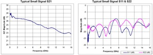
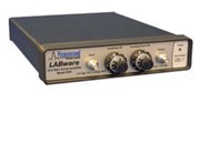
The PSPL8001 12.5 Gb/s Driver Amplifier LABware Module is designed for bench-top lab use. This LABware module can simply be plugged in with a line cord (either 110 V or 220 V) and the driver amplifier is ready for use. The PSPL8001 is ideal for driving Lithium Niobate optical modulators using NRZ signals for test and characterization experiments. The PSPL8001 can also be used as a linear amplifier with 26 dB gain and 12 GHz bandwidth for inputs less than ±150 mV (300 mVp-p with 50% duty cycle).
Key performance specifications
- LABware bench-top instrument
- 12.5 Gb/s Driver Amplifer
- 7.5 Vpp output amplitude
- Linear amplifier with 26 dB gain
- 30 kHz to 12 GHz bandwidth
- Integrated power supplies, amplitude, and crossing-point controls
Typical performance

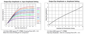
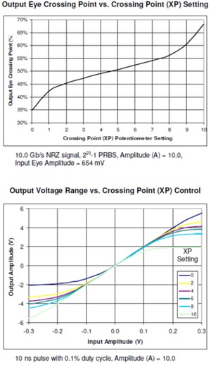
The Amplitude (A) control has very little effect on the output voltage under small signal conditions. Generally, it should be set to 10.0 when the PSPL8001 is used as a linear amplifier. The Crossing Point (XP) control sets the bias point of the amplifier. It should be set to 5.0. Both the Amplitude (A) and Crossing Point (XP) controls have locking levers. Be sure that the locks are released before rotating the knobs.
The Crossing Point (XP) control provides an adjustment for the crossing point of NRZ signals. By shifting the bias point, it can also compensate for NRZ signals that do not have a Mark Ratio of 1:2, RZ signals, or signals with low or high duty cycles.
The PSPL8001 is AC-coupled at the Input and Output, and the average value of the output signal (the DC component) must be at 0 V. Most NRZ data streams are conditioned to have a 50% duty cycle when averaged over a long period, about a microsecond. Those signals make full use of the positive and negative halves of the amplifier’s operating range.
The average amplitude of low duty cycle signals can be virtually at the baseline. These signals use only one half of the PSPL8001 operating range, and the maximum output amplitude may be 4 V instead of 8 V. The Crossing Point (XP) control can shift the amplifier’s operating point and increase the output amplitude up to 6 V in some cases.
It is recommended that the PSPL8001 be driven with a negative polarity signal when the duty cycle is very low. Narrow positive pulses can generate excessive heat within the PSPL8001 and damage the amplifier. Similarly, large duty signals should be positive.
Typical 10.66 Gb/s eye measurements
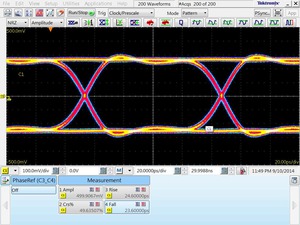
Input from Tektronix PPG1601, PRBS=223–1, 500 mv
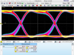
Output amplitude > 8 V
Caution: The PSPL8001 contains a static sensitive amplifier. To avoid damage from static electricity, always short the terminals of a device before connecting it to the input or output of the PSPL8001. Even coax cables must be shorted before making the connection.
Specifications
Large signal conditions
| Parameter | Symbol | Units | Minimum | Typical | Maximum | Comments |
|---|---|---|---|---|---|---|
| Impedance | Z | ohms | 50 | |||
| Output Eye Voltage with Amplitude (A) control = 10.0 |
VOUT | Vamp | 7.0 | 7.5 | Vin = 0.5 Vamp, 12.5 Gb/s PRBS | |
| Output Eye Voltage with Amplitude (A) control = 0.0 |
VOUT | Vamp | 3.2 | 4.0 | Vin = 0.5 Vamp, 12.5 Gb/s PRBS | |
| Rise Time | tr | ps | 22 | 28 | 20-80%, Vin = 0.5 Vamp, 12.5 Gb/s PRBS | |
| Fall Time | tf | ps | 24 | 30 | ||
| Additive Jitter RMS Peak-to-Peak |
ps pspp |
0.7 4 |
2.0 8 |
Vin = 0.5 Vamp, 12.5 Gb/s PRBS, meas. at crossing point | ||
| Crossing Point (XP) Adjust, Amplitude (A) control = 10.0 | % | ±10 | ±15 | Vin = 0.5 Vamp | ||
| Overshoot | % | 5 | 12.5 Gb/s PRBS | |||
| Undershoot | % | 5 | 12.5 Gb/s PRBS | |||
| Polarity | Non-Inverting | |||||
| Coupling | AC, input and output | |||||
| RF Connectors | SMA jacks (f) | |||||
Operating specifications
| Parameter | Comments |
|---|---|
| Max Allowed Input | 1.5 Max Vamp (damage threshold for input) |
| AC Power | 100, 117, 200, or 230 VAC, 50/60 Hz, 15VA (60 Hz) |
| Environment Operating Storage |
(Indoors, 80% relative humidity) 20 to 30 °C 0 to 50 °C |
| Safety Certifications | Conforms to EN-061010-1 (CE mark), UL-1244 and IEC-348. Safety class I. For lab use by qualified personnel. |
| Dimensions | 9.6 x 7.5 x 1.7 in. (244 x 190 x 33 mm) |
| Weight | 3.3 lbs. (1.5 kg) |
| Accessories | USA power cord |
| Warranty | One Year |
Ordering information
Models
- PSPL8001
- DRIVER AMPLIFIER, 12.5G b/s, LABware

