
Contact us
Live Chat with Tek representatives. Available 6:00 AM - 4:30 PM
Call us at
Available 6:00 AM – 5:00 PM (PST) Business Days
Download
Download Manuals, Datasheets, Software and more:
Feedback
16 Gb/s, 30 Gb/s, and 32 Gb/s PatternPro® Pattern Generator
PPG1600, PPG3000, and PPG3200 Series Datasheet
The products on this datasheet are no longer being sold by Tektronix.
View Tektronix Encore for reconditioned test equipment.
Check support and warranty status for these products.
More Information
- Máy tạo mẫu đa kênh PatternPro® PPG Series
- Explore more Software models
Read Online:
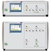
The Tektronix PatternPro® series programmable pattern generators provide up to four channels of stressed pattern generation for high-speed Datacom testing.
Notice to EU customers
This product is not updated to comply with the RoHS 2 Directive 2011/65/EU and will not be shipped to the EU. Customers may be able to purchase products from inventory that were placed on the EU market prior to July 22, 2017 until supplies are depleted. Tektronix is committed to helping you with your solution needs. Please contact your local sales representative for further assistance or to determine if alternative product(s) are available. Tektronix will continue service to the end of worldwide support life.
Key performance specifications
- Low inherent jitter (typical RJ <250 fs)
- 11 ps typical 20% to 80% rise/fall times
- Variable output amplitude:
- 300 mV to 1.0 V for PPG3200
- 250 mV to 2.0 V for PPG1600 and PPG3000 series
- Low frequency, high amplitude jitter insertion range of 10 Hz to 10 MHz at up to 5000 UI (PPG3200 series with Option LFJIT)
- BUJ amplitudes up to 50 psp-p with modulation rates up to 2.5 Gb/s (with Option HFJIT)
- 35% to 65% programmable crossing point (PPG1600 & PPG3000 series)
Key features
- Available with 1, 2, or 4 output channels of 16, 30, or 32 Gb/s (independent data on all channels)
- Provides full end-to-end multi-channel BER test solution when paired with the PED series error detector
- Jitter insertion options include BUJ, SJ, RJ, and PJ
- Aligned data on multi-channel units
- Full rate built-in adjustable clock source
- DC coupled differential data outputs
- Programmable output amplitude, offset, and crossing point
- PRBS and user defined patterns
- Adjustable channel phase delay
- Front panel touch screen GUI or USB computer control
Applications
- Multi-channel 25 Gb/s testing for 100 G Ethernet
- DQPSK and DP-QPSK testing
- CFP2 and CFP4 testing
- Multi-level signal testing
- Semiconductor and component testing
Product description
The Tektronix PatternPro® line of high-performance pattern generators offer single and multi-channel configurations capable of data rates up to 32 Gb/s. With optional jitter insertion, the PPG line offers a flexible, cost effective and easy to use test solution supporting high speed applications such as 100 Gigabit Ethernet, 32G Fibre channel, PAM4, DP-QPSK testing, and a broad range of receiver test applications. The single unit multi-channel configurations provide aligned, pattern-independent data outputs that support testing of crosstalk immunity and multi-channel functionality. The PPG line can be paired with the Tektronix PED line of Error Detector products to provide a complete BER test capability.
Data rate may be programmed over a broad range of values. (32 Gb/s version shown) Output may be either built-in PRBS patterns or programmed user data patterns.

100G Ethernet four lane end-to-end test using PPG3000 series pattern generator and PED3200 series error detector
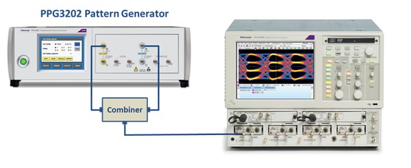
PPG3202 2-channel PG unit configured with external combiner for PAM4 signal operation
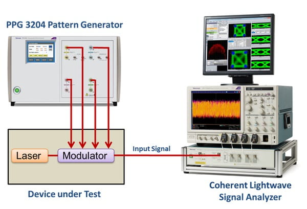
PPG3204 4-channel PG unit configured for DP-QPSK testing with Tektronix Coherent Lightwave Signal Analyzer
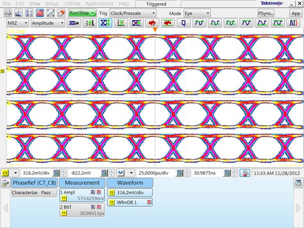
Four channel independent output data at 32 Gb/s
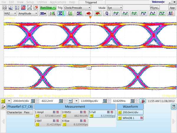
32 Gb/s and 14 Gb/s programmed data rates
Independently programmable output channels allow comprehensive multi-lane testing. (32 Gb/s version shown.)
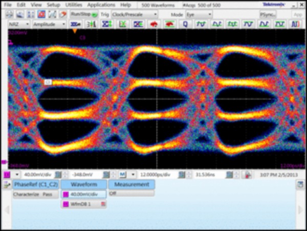
PAM4 eye diagram at 28 Gbaud
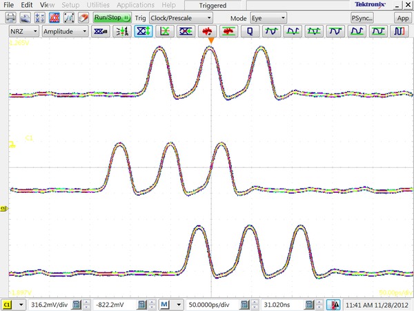
32 Gb/s custom user data demonstrating programmed data skew values
Specifications
All specifications are guaranteed unless noted otherwise. All specifications apply to all models unless noted otherwise.
PPG3200 data outputs
- Amplitude
- Each positive and negative differential output is independently programmable.
- Single-ended
- 300 mV to 1.0 V
- Differential
- 600 mV to 2.0 V
- Offset window
- -2 V to +3 V, programmable/adjustable
- Rise/fall time
- Scope bandwidth can impact the measured signal rise time.
- 20 to 80%
- 11 ps, typical
- 10 to 90 %
- 16 ps, typical
- Termination voltage range
-2.0 V to +3.3 V window. Programmable/adjustable. Applied by user via 50 Ω.
This setting is used in cases where the load being driven is terminated at a level other than zero volts. The effect of the termination voltage on the output voltage is shown in the following figure. To ensure proper operation, never load the output with a termination voltage less than Voh minus 3 V.

- Data output jitter
- 250 fsRMS RMS RJ typical at 32 Gb/s using PRBS 211-1 pattern
- Connector type
- 2.4 mm
- Output impedance
- 50 Ω
- Single-ended
- 100 Ω
- Differential
PPG3000 & PPG1600 data outputs
- Amplitude range
- 250 mV to 2.0 V
- Single-ended
- 500 mV to 4.0 V
- Differential. Each positive and negative differential output is independently programmable.
- Offset range
- –2 V to +3.0 V window. Programmable/adjustable.
- Termination voltage range
-2.0 V to +3.3 V window. Programmable/adjustable. Applied by user via 50 Ω.
This setting is used in cases where the load being driven is terminated at a level other than zero volts. The effect of the termination voltage on the output voltage is shown in the following figure. To ensure proper operation, never load the output with a termination voltage less than Voh minus 3 V.

- Crossing point
- Programmable/adjustable
- Range
- 35% to 65%, typical. Tested using 50% mark density pattern.
- Resolution
- 1%
- Rise/fall time
- Scope bandwidth can impact the measured signal rise time.
- 20% - 80%
- 17 ps, typical
- 10% - 90%
- 25 ps, typical
- Data output jitter
- PPG3000
- 350 fsRMS, RJ typical at 28 Gb/s using PRBS 211-1 pattern
- PPG1600
- 350 fsRMS, RJ typical at 14 Gb/s using PRBS 211-1 pattern
- Connector type
- 2.92 mm
- Output impedance
- 50 Ω
- Single-ended
- 100 Ω
- Differential
Data patterns
- Pattern type
- Data (from memory) or PRBS. Length and type are individually settable on multi-channel generators.
- Data rate
- Programmable/adjustable
- Range
- 1.5 Gb/s to 16 Gb/s, (PPG1600 series)
1.5 Gb/s to 30 Gb/s, (PPG3000 series)
1.5 Gb/s to 32 Gb/s (PPG3200 series)
- Resolution
- 10 kb/s
- Accuracy
- ±5 ppm
- PRBS pattern lengths
- Independently selected on multi-channel units
- 27 -1 bits
- Polynomial = X7 + X6 + 1
- 29 - 1 bits
- Polynomial = X9 + X5 + 1
- 211 - 1 bits
- Polynomial = X11 + X9 + 1
- 215 - 1 bits
- Polynomial = X15 + X14 + 1
- 223 - 1 bits
- Polynomial = X23 + X18 + 1
- 231 - 1 bits
- Polynomial = X31 + X28 + 1
- Data pattern depth
- Range
- 2 to 4,194,304 bits. For 1 channel generator (4 Mbits).
2 to 2,097,152 bits. For 2 or 4 channel generators (2 Mbits/channel).
- Resolution
- 1 bit
Clock outputs
- Frequency
- The clock outputs are single-ended, applicable for internal clock. The internal clock rate ranges from 15 GHz to 30 GHz (PPG3000 series) and 16 GHz to 32 GHz (PPG1600 and PPG3200 series).
- PPG1600 Clock output frequency
- (Internal clock)/(n), n = 2,4,8, or 16 user programmable
- PPG3000 Clock output frequency
- (Internal clock)/(n), n = 1,2,4,8, or 16 user programmable
- PPG3200 Divided Clock output frequency
- (Internal clock)/(n), n = 2,4,8, or 16 user programmable
- PPG3200 Full Rate Clock output frequency (single output for PPG3201/2, quad output for PPG3204)
- Internal clock
- Amplitude
- Amplitude varies with frequency
600 mVp-p, typical; 200 mVp-pminimum; 1.0 Vp-pmaximum
- Output impedance
- 50 Ω, AC-coupled
- Maximum external DC voltage
- ±5 V
- Jitter
- < 200 fsRMS typical, measured by spectrum analyzer on 1010 pattern, phase noise integrated from 1 kHz to 1 GHz.
- Connector type
- 2.92 mm (PPG3000 & PPG1600)
2.4 mm (PPG3200)
Jitter insertion
The pattern generator can be ordered with built-in jitter options. The PPG3200 series are available with Option LFJIT and Option HFJIT; the PPG1600 and PPG3000 series are available with Option HFJIT only. The jitter insertion is the delay modulation of the data channels. Option HFJIT applies to each channel individually; Option LFJIT applies equally to clock and data.
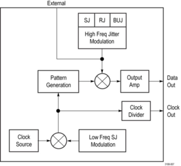
Jitter insertion block diagram
- High frequency jitter insertion option (Option HFJIT)
Add-on option for the instrument. Independent jitter sources on each channel. Sum of external, internal sine, and internal noise. Total range depends on modulation frequencies. Exceeding the range can generate errors.
- Total modulation range
- 50 psp-p
- Built-in sine source
- Programmable from either the front panel touch screen or remote control.
- Frequency range
- 5 kHz to 100 MHz
- Amplitude range
- 0 to 50 psp-p
- Accuracy
- ±10%, typical
- Built-in random noise source
- Programmable from either the front panel touch screen or remote control.
- Amplitude range
- 0 to 5 psRMS
- Accuracy
- ±10% typical
- Built-in BUJ source
- Programmable from either the front panel touch screen or remote control.
- Amplitude range
- 0 to 50 psp-p
- Modulation data rates
- 100 Mb/s to 2.5 Gb/s
- PRBS sequences
- 7,9,11,15,23,31
- Filter values
- 25/50/100 MHz filters
- External modulation input
- DC coupled, 3 dB bandwidths
- Frequency range
- DC to 100 MHz
- Amplitude range
- 0 to 50 ps p-p
- Maximum input
- 5 Vp-p
- Low frequency jitter insertion (Option LFJIT)
- Add-on option.
The specifications below apply when the data rate equals the internal clock rate frequency of 20 to 40 GHz. For each frequency octave below, the internal clock rate, the specifications below will be reduced by half. For example, when the data rate is 8 to 15.99999 Gb/s, the values below will be divided by 2. When the data rate is 4 to 7.99999 Gb/s, the values will be divided by 4.
- SJ modulation range curve points
Parameter Value 10 Hz fmod 5000 UIp-p 100 Hz fmod 2000 UIp-p 1 kHz fmod 2000 UIp-p 10 kHz fmod 2000 UIp-p 100 kHz fmod 100 UIp-p 1 MHz fmod 10 UIp-p 2 MHz fmod 1 UIp-p 10 MHz fmod 0.5 UIp-p 
Trigger system
- Trigger waveform
- Pattern mode trigger is synced to channel 1 pattern.
- Pattern mode
- 1 pattern per trigger for pattern length = multiple of 64
64 patterns per trigger for other pattern lengths
- Clock/n mode
- 64 through (232 - 64), n= any multiple of 64 in that range
- Duty cycle
- 50%, for either Pattern or Clock/n
- High level
- 0 V, typical
- Low level
- -500 mV, typical
- Output impedance
- 50 Ω, DC-coupled
- Connector type
- SMA
Clock inputs
- Frequency range
- 15 GHz to 30 GHz, (PPG3000 series)
16 GHz to 32 GHz, (PPG3200 series)
Not applicable for the PPG1600 series.
- Input signal
- 400 mVp-p, typical, AC coupled
- Maximum input signal
- 1 Vp-p
- Input impedance
- 50 Ω, AC-coupled
Reference clock
- Input frequency range
- 10 MHz ±10 ppm
- Input signal
- 1 Vp-p, typical, 50% duty square wave
- Maximum input signal
- 6 Vp-p, ±10 V DC, Damage threshold
- Input impedance
- 50 Ω, AC-coupled
- Output signal
- 1.2 Vp-p, typical, Square wave
- 10 MHz reference input/output
- Yes, BNC connector
Channel skew
- Skew adjust
- Relative to nominal position
- PPG1600 and PPG3000
Range = ±50 ps
Resolution = 100 fs
- PPG3200
Range = ±25 ps
Resolution = 100 fs
- Pattern shift
- Advance or delay. This is equivalent to unlimited shifting since this range allows shifting the longest pattern to any position.
- Range
- ± (230-1)
- Resolution
- 1 bit
- Nominal channel to channel pattern skew
- < ±2 UI, Time difference between patterns on a 2 channel PPG3000 series, skew adjust and bit shift at 0.
Data error insertion
- Error insertion types
- Single or rate-based
- Error insertion rate
- Range
- 1 x 10⁻³ to 1 x 10-15 BER
- Resolution
- 3 digits
Control interfaces
- Front panel touchscreen GUI
- Yes, edit all instrument settings.
- Computer programmable interface
- USB TMC, program all instrument settings.
Physical characteristics
- Front panel width (with mounting tabs)
- 48.3 cm (19.0 in)
- Height
- 1 & 2 channel
- 13.3 cm (5.25 in)
- 4 channel
- 27.9 cm (11.0 in)
- Width
- 45.1 cm (17.75 in)
- Depth (rack mount)
- 35.1 cm (13.8 in)
- Weight
- 1 & 2 channel
- 11.1 kg (24.5 lbs)
- 4 channel
- 20.4 kg (45 lbs)
- Operating temperature
- 0 °C to 40 °C (32 °F to 104 °F)
Ordering information
Models
- PPG1601
- 16 Gb/s programmable pattern generator, 1 channel
- PPG1602
- 16 Gb/s programmable pattern generator, 2 channels
- PPG1604
- 16 Gb/s programmable pattern generator, 4 channels
- PPG3001
- 30 Gb/s programmable pattern generator, 1 channel
- PPG3002
- 30 Gb/s programmable pattern generator, 2 channels
- PPG3004
- 30 Gb/s programmable pattern generator, 4 channels
- PPG3201
- 32 Gb/s programmable pattern generator, 1 channel
- PPG3202
- 32 Gb/s programmable pattern generator, 2 channels
- PPG3204
- 32 Gb/s programmable pattern generator, 4 channels
Options
Instrument options
- PPG1601 HFJIT
- High frequency jitter option for PPG1601
- PPG1602 HFJIT
- High frequency jitter option for PPG1602
- PPG1604 HFJIT
- High frequency jitter option for PPG1604
- PPG3001 HFJIT
- High frequency jitter option for PPG3001
- PPG3002 HFJIT
- High frequency jitter option for PPG3002
- PPG3004 HFJIT
- High frequency jitter option for PPG3004
- PPG3201 HFJIT
- High frequency jitter option for PPG3201
- PPG3202 HFJIT
- High frequency jitter option for PPG3202
- PPG3204 HFJIT
- High frequency jitter option for PPG3204
- PPG3201 LFJIT
- Low frequency jitter option for PPG3201
- PPG3202 LFJIT
- Low frequency jitter option for PPG3202
- PPG3204 LFJIT
- Low frequency jitter option for PPG3204
Power plug options
- Opt. A0
- North America power plug (115 V, 60 Hz)
- Opt. A1
- Universal Euro power plug (220 V, 50 Hz)
- Opt. A2
- United Kingdom power plug (240 V, 50 Hz)
- Opt. A6
- Japan power plug (100 V, 50/60 Hz)
- Opt. A10
- China power plug (50 Hz)
- Opt. A11
- India power plug (50 Hz)
- Opt. A99
- No power cord
Manuals
- 071-3413-xx
- Printed PPG/PED Installation & Safety instructions
- 077-1090-xx
- Tektronix PPG1600, PPG3000, & PPG3200 PatternPro® Series Pattern Generator User manual, PDF-only, downloadable from Tektronix.com


