A GUIDE TO THE RADIO SPECTRUM

WHAT’S A SPECTRUM DISPLAY?

Additional Information:
WikipediaGet a quick and inexpensive look at wireless signals with the USB Spectrum Analyzers.
A spectrum analyzer is the tool of choice for people who need to “see” a radio signal. In general most spectrum analyzers provide the same display; they show lower frequency signals on the left hand side of the display and higher frequency signals on the right hand side of the display. The three basic controls for most spectrum analyzers are; Frequency, Span & Amplitude (Reference Level). With these three controls we can control the view of the spectrum. The next question is “what am I looking at?”
We can tell a lot about an RF signal from the basic spectrum display. It certainly helps to know what you are looking for. Around the world there is a lot of dedicated spectrum assignment, meaning certain frequency ranges are used for certain types of radio signals.
The first step in identifying a radio signal is to determine the operating frequency of the transmitter. Other than Industrial/Scientific/Medical bands, the radio spectrum is a tightly managed resource. When we are trying to determine what type of signal we are seeing, we need to first identify the operating frequency. A simple technique is to look at the total width of the signal and find the mid-point in the signal. In general this will indicate the operating frequency. With this first piece of information we can now research frequency assignment tables to determine what type of radio service may be assigned to specific frequency.
The second piece of information that is important is how “wide” the signal is that is shown on the spectrum display. The “width” or occupied bandwidth of the signal provides us additional information regarding the class of service of the transmitter. We know for example that in the 2.4 GHz ISM frequency band, a Bluetooth signal is approximately 1 MHz wide but a Wi-Fi signal could be up to 40 MHz wide.
In summary, the basic spectrum display allows us to determine the frequency, occupied bandwidth and relative strength of a radio transmitter.
WHAT’S A SPECTROGRAM DISPLAY?

Additional Information:
WikipediaUsing spectrogram displays in the lab using the RSA600 series spectrum Analyzer.
While it’s very important to determine frequency, occupied bandwidth and relative signal strength; we also need to find out how often a signal is on.
The spectrogram display is the one of the best ways for us to measure this aspect of a signal. Like the spectrum display the spectrogram shows low frequencies on left and higher frequencies on the right. What makes this display different is that color represents the amplitude of the signal, and the Y-Axis is Time. You can think of a spectrogram as a strip chart recorder measuring power and frequency over a time period.
The spectrogram provides important information as it can tell us how often a signal is present, and indicates if the operating frequency is changing over time. These two pieces of information are critical in identifying the class of service of a particular emission.
Armed with frequency, occupied bandwidth, and time data; it is possible to make accurate assessments of the type of radio emitter that is being analyzed.
WHAT IS A REAL-TIME DISPLAY?
Take Tektronix USB spectrum analyzers into the field for fast RF analysis and geo-location.
In the past decade there has been a gradual shift toward real-time spectrum displays. While classic spectrum displays have been around since the 1960’s, they have all suffered from a common problem, speed. In most traditional spectrum analyzers what is displayed on the left hand side of the display and the right hand side of the display is not measured at the same time. The instrument sweeps across the frequency range making measurements over time. To overcome this shortcoming spectrum analyzers employ specific trace modes (max hold, min hold, average etc) to improve the ability of the analyzer to measure a specific signal.
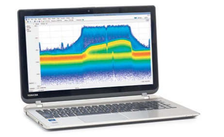
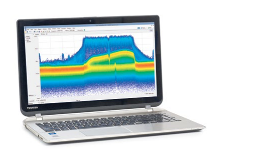
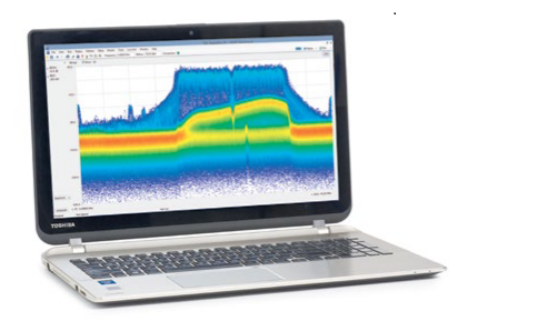
Real-time spectrum analyzers function and operate the same way traditional spectrum analyzers. The difference with real-time analyzer is that in up to the maximum real-time span, these analyzers do not sweep the spectrum, but rather instantaneously digitize the whole span. The real-time span could be limited by the instantaneous bandwidth of the instrument, and they can digitize signals extremely quickly. Real time spectrum analyzers with that capability can produce results measured in thousands of traces per second. This has led to an upgrade of the basic spectrum display with the Digital Phosphor Display (DPX). In the DPX display we still have low frequency on the left and high frequency on the right hand side of the display.
Rather than producing a single trace real time analyzers are able to keep track of how often a signal is measured for each pixel in the display. There is a counter behind each pixel that keeps track of how often energy is measured, and the pixel color is based on this counter. Real-time analyzers also employ a decay function, just like what was found on traditional CRT displays. This combination provides an extremely useful tool for analyzing fast frequency hopping signals like Bluetooth, or for isolating tough transients that can be virtually invisible to slow sweeping spectrum analyzers.
Note that the RSA306’s Span setting is not constrained to the real-time bandwidth. Rather, the DPX display can be swept in steps across the instrument’s entire 6.2 GHz frequency range. The same is true for the Spectrum Analyzer displays. In general, the RSA306 with SignalVu-PC software has conventional spectrum analyzer controls as well as powerful real-time capabilities.
SIGNAL CLASSIFICATION 101
Identifying signals you measure with a spectrum analyzer can be difficult even with the best of tools. The radio spectrum is a shared resource and the propagation characteristics change for each frequency band.
What follows are some guiding principals about radio transmissions. When you find a signal of interest, whether this is signal that should or should not be present in a particular frequency band, you would want to start with the basics.
The first step is to look at the frequency, bandwidth, and shape of a signal of interest to get an idea about the characteristics & therefore the identity of this signal. For example, many of the 3G and 4G signals have square tops due to the type of filtering they use. Also, these commercial wireless signals use predicable bandwidths. You can make an educated guess on the signal type based on what you see on the screen.
Other signal types will have different information bandwidths and different filtering employed, therefore they will have a different shape on the Spectrum Analyzer display or the Real-Time display of an analyzer.
The second step is to perform modulation analysis of the signal. Analyzing the modulation will give further insight into more of the unique characteristics of a signal. The fastest, simplest, and most common way of doing this is to take advantage of a spectrum analyzer’s Audio Demodulation feature – to play the FM or AM audio out the instrument of the signal of interest. Your ear can hear differences in signals.
There are limitations using this method, for example the Audio Demodulation of an analyzer may have a much smaller bandwidth compared to the signal of interest bandwidth. However, there are often distinguishable sounds from various signals seen throughout the spectrum, and this method is a proven technique to help identify signals.
The third step is to capture the signal data and perform additional analysis of the signal. This can be a difficult technique because based on some experience, trial and error would be used within the RF measurement software capabilities to try to determine more characteristics of the signal. For example, you could look at the RF IQ vs. Time to try to figure out a digital modulation Symbol Rate, or look at the Spectrogram to try to check for the presence of OFDM subcarriers.
UNLICENSED/ISM BANDS
Unlicensed bands – constrained by power and frequency, many consumer (Wi-Fi, Key FOBS) and medical devices use these frequencies.
Example Application
- WLAN 802.11b
- WLAN 802.11g
- Microwave Oven
- DECT Cordless Phone
- Bluetooth
WIFI – 802.11B
Technical Overview
- Modulation: CCK
- Source: Data
- Channel Bandwidth: 20 MHz
- Channel Occupancy: TDMA

WIFI – 802.11G
Technical Overview
- Modulation: OFDM
- Source: Data
- Channel Bandwidth: 20/40 MHz
- Channel Occupancy: TDMA

MICROWAVE OVEN
Technical Overview
- Modulation: CW
- Source: CW
- Channel Bandwidth: 20 MHz
- Channel Occupancy: CW

DECT
Technical Overview
- Modulation: GFSK
- Source: Data
- Channel Bandwidth: < 2.5 MHz
- Channel Occupancy: TDMA
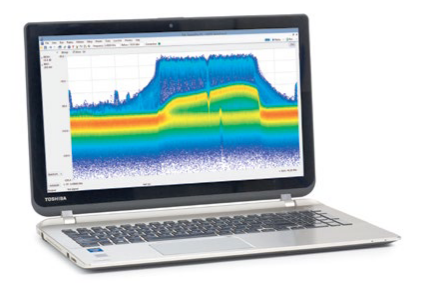
BLUETOOTH
Technical Overview
- Modulation: GFSK,p1/4DQPSK
- Source: Data
- Channel Bandwidth: ~ 1 MHz
- Channel Occupancy: FH/TDMA
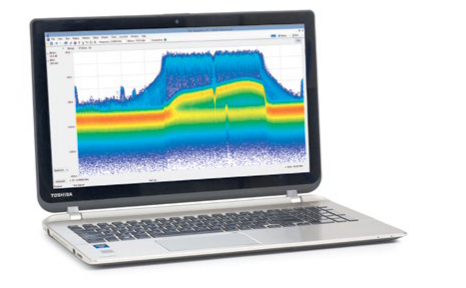
LAND MOBILE RADIO
Trunked radio, Public and Private Mobile Radio, Distributed.
Example Application
- P25 Phase 1
- Narrow Band FM
- NXDN
P25 Phase 1
Technical Overview
- Modulation: 4FSK
- Source: Data
- Channel Bandwidth: 6 kHz – 25 kHz
- Channel Occupancy: PTT
Common Frequency Range
- 138 MHz – 174 MHz
- 410 MHz – 512 MHz
- 806 MHz – 902 MHz
- 928 MHz – 975 MHz
Additional Information:
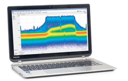
NARROW BAND FM
Technical Overview
- Modulation: FM
- Source: Analog Audio
- Channel Bandwidth: 6 kHz – 25KHz
- Channel Occupancy: PTT
Common Frequency Range
- 25 MHz – 49.6 MHz
- 138 MHz – 174 MHz
- 410 MHz – 512 MHz
- 806 MHz – 902 MHz
- 928 MHz – 975 MHz
Additional Information:
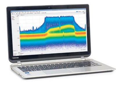
NXDN
Technical Overview
- Modulation: 4FSK
- Source: Data
- Channel Bandwidth: < 25 kHz
- Channel Occupancy: PTT
Common Frequency Range
- 138 MHz – 174 MHz
- 410 MHz – 512 MHz
- 806 MHz – 902 MHz
- 928 MHz – 975 MHz
Additional Information:
RADIO AND TELEVISION BROADCAST
Broadcast frequencies – Radio and Television applications, including short wave and hobbyist spectrum. sometimes under-utilized, long time owned by broadcasters.
Example Application
- FM Radio
- ATSC – Terrestrial TV
FM RADIO
Technical Overview
- Modulation: FM/IBOC
- Source: Analog/Data
- Channel Bandwidth: 250 kHz – 300 kHz
- Channel Occupancy: Continuous
ATSC – TERRESTRIAL TV
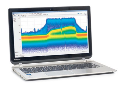
Technical Overview
- Modulation: 8VSB
- Source: Data
- Channel Bandwidth: 6 MHz
- Channel Occupancy: Continuous
Common Frequency Range
- 54 MHz – 88 MHz
- 174 MHz – 216 MHz
- 470 MHz – 806 MHz
- ATSC Frequencies NA
Additional Information:
CELLULAR
Extremely crowded and expensive spectrum. Used for mobile data and voice communications. Often replaces a hard wired communication line.
Example Application
- LTE Downlink
- LTE Uplink
- UMTS Downlink
- UMTS Uplink
- GSM
LTE DOWNLINK
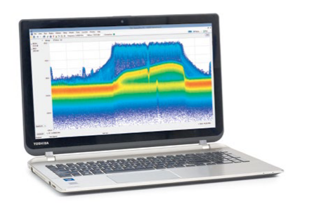
Technical Overview
- Modulation: OFDM(TDMA/FDMA)
- Source: Data
- Channel Bandwidth: 1-20 MHz
- Channel Occupancy: Continuous
Common Frequency Range
- 590 MHz – 610 MHz
- 715 MHz – 765 MHz
- 1930 MHz – 2000 MHz
- 2110 MHz - 2180 MHz
- 2345 MHz – 2360 MHz
- LTE Frequency Bands
Additional Information:
LTE UPLINK
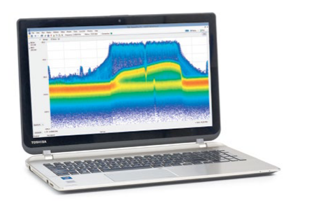
Technical Overview
- Modulation: OFDM
- Source: Data
- Channel Bandwidth: 1-20 MHz
- Channel Occupancy: TDMA/FDMA
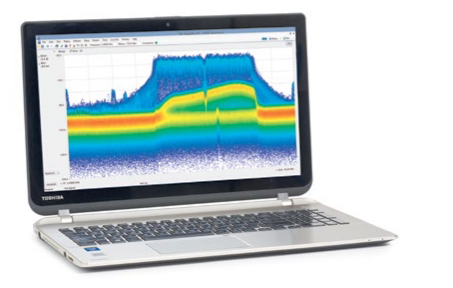
UMTS DOWNLINK
Technical Overview
- Modulation: CDMA
- Source: Data
- Channel Bandwidth: 3.84 MHz
- Channel Occupancy: Continuous
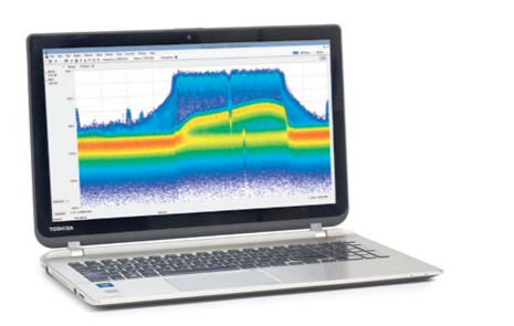
UMTS UPLINK
Technical Overview
- Modulation: CDMA
- Source: Data
- Channel Bandwidth: 3.84 MHz
- Channel Occupancy: Continuous
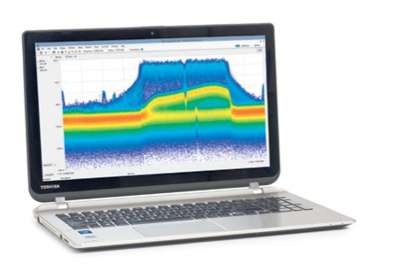
GSM
Technical Overview
- Modulation: GMSK
- Source: Data
- Channel Bandwidth: 200 kHz
- Channel Occupancy: TDMA/FDMA
Common Frequency Range
- 824 MHz – 849 MHz
- 869 MHz – 894 MHz
- 1850 MHz –1910 MHz
- 1930 MHz – 2000 MHz
Additional Information:
AERONAUTICAL
Civilian flight control and communications bands. Includes Radars for aircraft tracking and navigation, communications, IFF.
Example Application
- Aeronautical Communications
AERONAUTICAL COMMUNICATIONS
Technical Overview
- Modulation: AM/FM
- Source: Analog/Data
- Channel Bandwidth: < 25 kHz
- Channel Occupancy: PTT
WEATHER RADAR
Commonly used spectrum for radar, electronic warfare, and communications. Could be land, sea, air or space based systems.
Example Application
- Weather Radar
RADAR
Technical Overview
- Modulation: FM/PM/CW
- Channel Bandwidth: < 50 MHz
- Channel Occupancy: Pulse
Common Frequency Range
- 5.6 GHz – 6 GHz
- 9 GHz – 10 GHz
Additional Information:
RESOURCES
- Resources
- Application
RESOURCES
Additional Information:
| RSA306B USB SPECTRUM ANALYZER |
RSA503A AND RSA507A USB SPECTRUM ANALYZER |
RSA603A AND RSA607A USB SPECTRUM ANALYZER |
|
| Frequency Range | 9 kHz to 6.2 GHz | RSA503A: 9 kHz - 3 GHz RSA507A: 9 kHz - 7.5 GHz |
RSA603A: 9 kHz - 3 GHz RSA607A: 9 kHz - 7.5 GHz |
| Capture Bandwidth | 40 MHz | 40 MHz | 40 MHz |
| SFDR | 60 dB | 70 dB | 70 dB |
| Tracking Generator | N/A | Available | Available |
| Portability | USB 3.0 Powered | Battery or AC Powered | AC Powered |
| Best Fit Environment | Field / Lab | Field | Lab |
| Popular Applications |
Use:
|
Field use:
|
Lab Applications such as:
|
| General Purpose RF Design | |||
| Starting Price | In the US, $3,890 | In the US, $5,900 (3 GHz), $9,900 (7.5 GHz) | In the US, $6,900 (3 GHz), $9,900 (7.5 GHz) |
APPLICATION
Ready for any challenges in the lab and in the field


Find more valuable resources at TEK.COM
Copyright © 2016, Tektronix. All rights reserved. Tektronix products are covered by U.S. and foreign patents, issued and pending. Information in this publication supersedes that in all previously published material. Specification and price change privileges reserved. TEKTRONIX and TEK are registered trademarks of Tektronix, Inc. All other trade names referenced are the service marks, trademarks or registered trademarks of their respective companies.
04/16 EA 37W-30937-1


