Kontaktaufnahme
Live-Chat mit Tektronix-Vertretern. Verfügbar von 9 bis 17 Uhr CET Geschäftstage.
Kontaktieren Sie uns telefonisch unter
Verfügbar von 9 bis 17 Uhr CET Geschäftstage.
Download
Laden Sie Handbücher, Datenblätter, Software und vieles mehr herunter:
Feedback
TPR1000 and TPR4000 User Manual
This document provides information for installing and using the TPR1000 and TPR4000 Active Power Rail Probes.
Dieses Handbuch bezieht sich auf:
TPR1000, TPR4000
By downloading, you agree to the terms and conditions of the Manuals Download Agreement.Manuals Download Agreement
ATTENTION: please read the following terms and conditions carefully before downloading any documents from this website. By downloading manuals from Tektronix' website, you agree to the following terms and conditions:
Manuals for Products That Are Currently Supported:
Tektronix hereby grants permission and license to owners of Tektronix instruments to download and reproduce the manuals on this website for their own internal or personal use. Manuals for currently supported products may not be reproduced for distribution to others unless specifically authorized in writing by Tektronix, Inc.
A Tektronix manual may have been revised to reflect changes made to the product during its manufacturing life. Thus, different versions of a manual may exist for any given product. Care should be taken to ensure that one obtains the proper manual version for a specific product serial number.
Manuals for Products That Are No Longer Supported:
Tektronix cannot provide manuals for measurement products that are no longer eligible for long term support. Tektronix hereby grants permission and license for others to reproduce and distribute copies of any Tektronix measurement product manual, including user manuals, operator's manuals, service manuals, and the like, that (a) have a Tektronix Part Number and (b) are for a measurement product that is no longer supported by Tektronix.
A Tektronix manual may be revised to reflect changes made to the product during its manufacturing life. Thus, different versions of a manual may exist for any given product. Care should be taken to ensure that one obtains the proper manual version for a specific product serial number.
This permission and license does not apply to any manual or other publication that is still available from Tektronix, or to any manual or other publication for a video production product or a color printer product.
Disclaimer:
Tektronix does not warrant the accuracy or completeness of the information, text, graphics, schematics, parts lists, or other material contained within any measurement product manual or other publication that is not supplied by Tektronix or that is produced or distributed in accordance with the permission and license set forth above.
Tektronix may make changes to the content of this website or to its products at any time without notice.
Limitation of Liability:
TEKTRONIX SHALL NOT BE LIABLE FOR ANY DAMAGES WHATSOEVER (INCLUDING, WITHOUT LIMITATION, ANY CONSEQUENTIAL OR INCIDENTAL DAMAGES, DAMAGES FOR LOSS OF PROFITS, BUSINESS INTERRUPTION, OR FOR INFRINGEMENT OF INTELLECTUAL PROPERTY) ARISING OUT OF THE USE OF ANY MEASUREMENT PRODUCT MANUAL OR OTHER PUBLICATION PRODUCED OR DISTRIBUTED IN ACCORDANCE WITH THE PERMISSION AND LICENSE SET FORTH ABOVE.
Read Online
OPERATING INFORMATION
- Theory of operation
- Environmental requirements
- Connecting to the instrument
- Probe controls and indicators
- Functional check
- Required instrument software versions
- Probe input
- Probe offset
- Connect MMCX accessories
- Connect solder-in accessories
- Using the solder-pin installation tool
- Using the tripod
- Using the optional browser
- Ground lead length
- Ground lead inductance
- Accessories
Important safety information
This manual contains information and warnings that must be followed by the user for safe operation and to keep the product in a safe condition.
General safety summary
Use the product only as specified. Review the following safety precautions to avoid injury and prevent damage to this product or any products connected to it. Carefully read all instructions. Retain these instructions for future reference.
This product shall be used in accordance with local and national codes.
For correct and safe operation of the product, it is essential that you follow generally accepted safety procedures in addition to the safety precautions specified in this manual.
The product is designed to be used by trained personnel only.
Only qualified personnel who are aware of the hazards involved should remove the cover for repair, maintenance, or adjustment.
Before use, always check the product with a known source to be sure it is operating correctly.
This product is not intended for detection of hazardous voltages.
Use personal protective equipment to prevent shock and arc blast injury where hazardous live conductors are exposed.
While using this product, you may need to access other parts of a larger system. Read the safety sections of the other component manuals for warnings and cautions related to operating the system.
When incorporating this equipment into a system, the safety of that system is the responsibility of the assembler of the system.
To avoid fire or personal injury
High temperature probe tips
 | WARNING:To prevent a burn injury, when using a solder micro-coax or flex tip in a high temperature application, be sure to allow the tip to cool down before handling the tip. |
Observe all terminal ratings
To avoid fire or shock hazard, observe all rating and markings on the product. Consult the product manual for further ratings information before making connections to the product.
Do not exceed the Measurement Category (CAT) rating and voltage or current rating of the lowest rated individual component of a product, probe, or accessory. Use caution when using 1:1 test leads because the probe tip voltage is directly transmitted to the product.
Do not apply a potential to any terminal, including the common terminal, that exceeds the maximum rating of that terminal.
Do not float the common terminal above the rated voltage for that terminal.
The measuring terminals on this product are not rated for connection to mains or Category II, III, or IV circuits.
Do not connect a current probe to any wire that carries voltages above the current probe voltage rating.
Do not operate without covers
Do not operate this product with covers or panels removed, or with the case open. Hazardous voltage exposure is possible.
Avoid exposed circuitry
Do not touch exposed connections and components when power is present.
Do not operate with suspected failures
If you suspect that there is damage to this product, have it inspected by qualified service personnel.
Disable the product if it is damaged. Do not use the product if it is damaged or operates incorrectly. If in doubt about safety of the product, turn it off and disconnect the power cord. Clearly mark the product to prevent its further operation.
Before use, inspect voltage probes, test leads, and accessories for mechanical damage and replace when damaged. Do not use probes or test leads if they are damaged, if there is exposed metal, or if a wear indicator shows.
Examine the exterior of the product before you use it. Look for cracks or missing pieces.
Use only specified replacement parts.
Wear eye protection
Wear eye protection if exposure to high-intensity rays or laser radiation exists.
Do not operate in wet/damp conditions
Be aware that condensation may occur if a unit is moved from a cold to a warm environment.
Do not operate in an explosive atmosphere
Keep product surfaces clean and dry
Remove the input signals before you clean the product.
Provide proper ventilation
Refer to the installation instructions in the manual for details on installing the product so it has proper ventilation.
Slots and openings are provided for ventilation and should never be covered or otherwise obstructed. Do not push objects into any of the openings.
Provide a safe working environment
Always place the product in a location convenient for viewing the display and indicators.
Avoid improper or prolonged use of keyboards, pointers, and button pads. Improper or prolonged keyboard or pointer use may result in serious injury.
Be sure your work area meets applicable ergonomic standards. Consult with an ergonomics professional to avoid stress injuries.
Probes and test leads
Before connecting probes or test leads, connect the power cord from the power connector to a properly grounded power outlet.
Keep fingers behind the protective barrier, protective finger guard, or tactile indicator on the probes. Remove all probes, test leads and accessories that are not in use.
Use only correct Measurement Category (CAT), voltage, temperature, altitude, and amperage rated probes, test leads, and adapters for any measurement.
| WARNING:To avoid electric shock, keep the probe wire as far from the tip and high voltage circuits as possible. The probe wire voltage rating is less than the probe tip voltage rating. Therefore the probe wire may not provide adequate protection. |
| WARNING:To avoid electric shock, do not use the probe if the wear indicator on the cable becomes visible. Contact Tektronix at tek.com for a replacement. |
Beware of high voltages
Understand the voltage ratings for the probe you are using and do not exceed those ratings. Two ratings are important to know and understand:
- The maximum measurement voltage from the probe tip to the probe reference lead.
- The maximum floating voltage from the probe reference lead to earth ground.
These two voltage ratings depend on the probe and your application. Refer to the Specifications section of the manual for more information.
| WARNING:To prevent electrical shock, do not exceed the maximum measurement or maximum floating voltage for the oscilloscope input BNC connector, probe tip, or probe reference lead. |
Connect and disconnect properly.
Connect the probe output to the measurement product before connecting the probe to the circuit under test. Connect the probe reference lead to the circuit under test before connecting the probe input. Disconnect the probe input and the probe reference lead from the circuit under test before disconnecting the probe from the measurement product.
De-energize the circuit under test before connecting or disconnecting the current probe.
Connect the probe reference lead to earth ground only.
Do not connect a current probe to any wire that carries voltages or frequencies above the current probe voltage rating.
Do not connect or disconnect probes or test leads while they are connected to a voltage source.
Use only insulated voltage probes, test leads, and adapters supplied with the product, or indicated by Tektronix to be suitable for the product.
Inspect the probe and accessories
Before each use, inspect probe and accessories for damage (cuts, tears, or defects in the probe body, accessories, or cable jacket). Do not use if damaged.
Ground-referenced oscilloscope use
Do not float the reference lead of this probe when using with ground-referenced oscilloscopes. The reference lead must be connected to earth potential (0 V).
Floating measurement use
Do not float the reference lead of this probe above the rated float voltage.
Service the probe and accessories
Go to tek.com/support to find information on contacting Tektronix Service Support.
Terms in this manual and on the product
These terms may appear in this manual:
| WARNING:Warning statements identify conditions or practices that could result in injury or loss of life. |
| CAUTION:Caution statements identify conditions or practices that could result in damage to this product or other property. |
These terms may appear on the product:
- DANGER indicates an injury hazard immediately accessible as you read the marking.
- WARNING indicates an injury hazard not immediately accessible as you read the marking.
- CAUTION indicates a hazard to property including the product.
Symbols on the product
 | When this symbol is marked on the product, be sure to consult the manual to find out the nature of the potential hazards and any actions which have to be taken to avoid them. (This symbol may also be used to refer the user to ratings in the manual.) |
The following symbols(s) may appear on the product.
 CAUTION: Refer to Manual |
Compliance information
This section lists the safety and environmental standards with which the instrument complies. This product is intended for use by professionals and trained personnel only; it is not designed for use in households or by children.
Compliance questions may be directed to the following address:
Tektronix, Inc.
PO Box 500, MS 19-045
Beaverton, OR 97077, US
tek.com
Safety compliance
This section lists the safety standards with which the product complies and other safety compliance information.
Equipment type
Test and measuring equipment.
Pollution degree description
A measure of the contaminants that could occur in the environment around and within a product. Typically the internal environment inside a product is considered to be the same as the external. Products should be used only in the environment for which they are rated.
- Pollution Degree 1. No pollution or only dry, nonconductive pollution occurs. Products in this category are generally encapsulated, hermetically sealed, or located in clean rooms.
- Pollution Degree 2. Normally only dry, nonconductive pollution occurs. Occasionally a temporary conductivity that is caused by condensation must be expected. This location is a typical office/home environment. Temporary condensation occurs only when the product is out of service.
- Pollution Degree 3. Conductive pollution, or dry, nonconductive pollution that becomes conductive due to condensation. These are sheltered locations where neither temperature nor humidity is controlled. The area is protected from direct sunshine, rain, or direct wind.
- Pollution Degree 4. Pollution that generates persistent conductivity through conductive dust, rain, or snow. Typical outdoor locations.
Pollution degree rating
Pollution Degree 2
IP rating
IPX0
Environmental compliance
This section provides information about the environmental impact of the product.
Product end-of-life handling
Observe the following guidelines when recycling an instrument or component:
- Equipment recycling
- Production of this equipment required the extraction and use of natural resources. The equipment may contain substances that could be harmful to the environment or human health if improperly handled at the product’s end of life. To avoid release of such substances into the environment and to reduce the use of natural resources, we encourage you to recycle this product in an appropriate system that will ensure that most of the materials are reused or recycled appropriately.
 |
This symbol indicates that this product complies with the applicable European Union requirements according to Directives 2012/19/EU and 2006/66/EC on waste electrical and electronic equipment (WEEE) and batteries. For information about recycling options, check the Tektronix Web site (http://www.tek.com/productrecycling). |
Preface
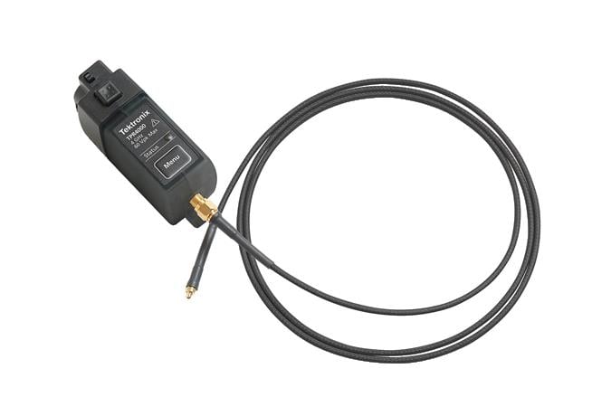
This manual describes the installation and operation of the TPR1000 and TPR4000 active power rail probes. Basic probe operations and concepts are presented in this manual. Access this document and other related information from tek.com.
The TPR1000 and TPR4000 probes provide a low noise, large offset range solution for measurement of ripple on DC power rails ranging from –60 to +60 VDC. Tektronix’s power rail probes offer industry leading low noise and high offset range required to measure AC ripple between 200 μVp-p and 800 mVp-p at up to 4 GHz.
Compatible with the 6 series MSO, 5 series MSO, 4 Series MSO, 3 Series MDO, MDO3000 , MDO4000C, MSO/DPO5000B, DPO7000C, and DPO70000C/DX/SX oscilloscopes. Due to software incompatibilities between the TPR1000 and TPR4000 probes and the MDO3000 and MDO4000C oscilloscopes, the accuracy of probe measurements is reduced when these oscilloscopes are used in vertical scale settings less than 2 mV/division. For all other vertical scale settings, the specified accuracy of the probe is maintained. DPO70000 oscilloscopes require the optional TCA-VPI50 adapter.
Why use a power-rail probe?
The added functionality, higher density, and faster switching speeds of modern electronic products drive the need for lower supply voltages. Designers need to zoom-in on power rails to look for high-frequency intruder signals, measure ripple and analyze coupling effects with tighter tolerances. Oscilloscopes often don't have enough offset to shift the noise and ripple on DC rails to the center of the screen to make the needed measurements.
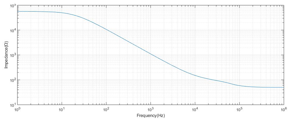
The TPR1000 and TPR4000 probes provide a low-noise measurement solution (oscilloscope and probe), which is critical to not confuse the noise of the oscilloscope and probe with the noise and ripple of the DC supply being measured. The higher input impedance in the probes minimize the oscilloscope loading effect on DC rails (50 kΩ at DC). The probes provide higher bandwidth to see more signal content (harmonics, faster ripples, etc.) on DC rails that could affect data signals, clocks, etc.
The TPR1000 and TPR4000 provide a best-in-class integrity solution for power integrity and validation engineers in the high speed (μP), low power (mobile) and switched-mode power supply markets. The probes are designed to offer the lowest noise with high bandwidth at 60 V offset, flexible connectivity options to cover customers challenges, and software packages to cover the digital power management market.
Operating information
Use this section to help you use the probe safely and effectively. Read all safety information before installing your measurement system to be aware of the operating and clearance requirements, including possible hazardous areas when the measurement system is connected to the device under test (DUT).
Theory of operation
The block diagram shows the major circuit blocks or modules in the TPR1000 and TPR4000 probes.
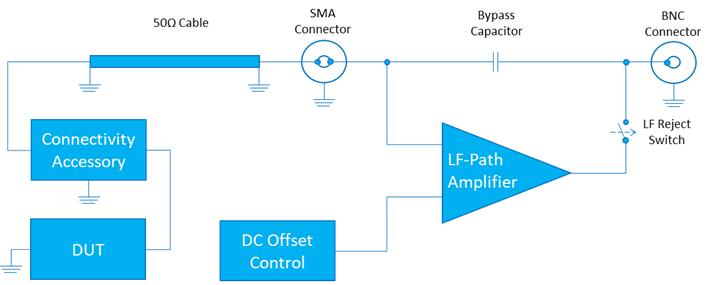
The TPR1000 and TPR4000 function by extending the oscilloscopes offset capability while maintaining a low noise signal path into the instrument. The linear dynamic range can be moved around the offset voltage operating window using the DC offset control into the LF amplifier. The LF amplifier can be disconnected when DC offset is not needed by setting the coupling mode to DC reject in the instrument vertical menu. The bypass capacitor acts as a low impedance path for high frequency components while blocking low frequency components. Because the TPR1000 and TPR4000 are designed for measuring the low source impedances of power distribution planes it is not recommended to measure devices with source impedances >1 Ω as it may cause distortion of the waveform.
Environmental requirements
| Characteristic | Description |
|---|---|
| Temperature | Probe body: 0 to +50 °C |
| Standard accessories: -40 to +125 °C | |
| High temp accessories: -55 to +155 °C | |
| Humidity | 5 to 95% up to +40 °C, derate to 85% above +40 °C |
| Altitude | Up to 3,000 meters (9,842 feet) |
| Dynamics (random vibration) | Operating: 5 to 500 Hz, 2.66 gRMS |
| Nonoperating: 5 to 500 Hz, 3.48 gRMS |
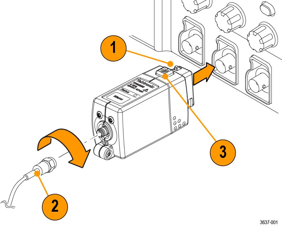
Connecting to the instrument
The following steps describe the process for connecting the TPR1000 and TPR4000 probes.
Procedure
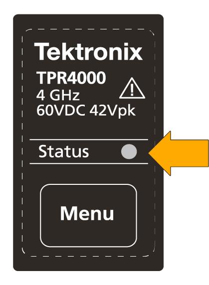
Probe controls and indicators
A description of the controls and indicators on the compensation box.
When the probe is powered on, the multicolor Status LED indicates the status of the probe.
| LED | Status | Action |
|---|---|---|
| Green (solid) | The probe has initialized and is in the normal operating mode. | - |
| Green (blinking) | The probe is connected, but has not initialized. | - |
| Red (any state) | An internal probe diagnostic fault exists. | Disconnect and reconnect the probe to restart the power-on diagnostic sequence. If the Status LED continues to be red or flashing for more than 30 seconds when the instrument application is running, the probe is defective and must be returned to Tektronix for repair. |
| Note:The TPR1000 and TPR4000 power rail probes are designed to work with all TekVPI-interface oscilloscopes and adapters. However, there may be some cases where all of the probe features may not work properly. |
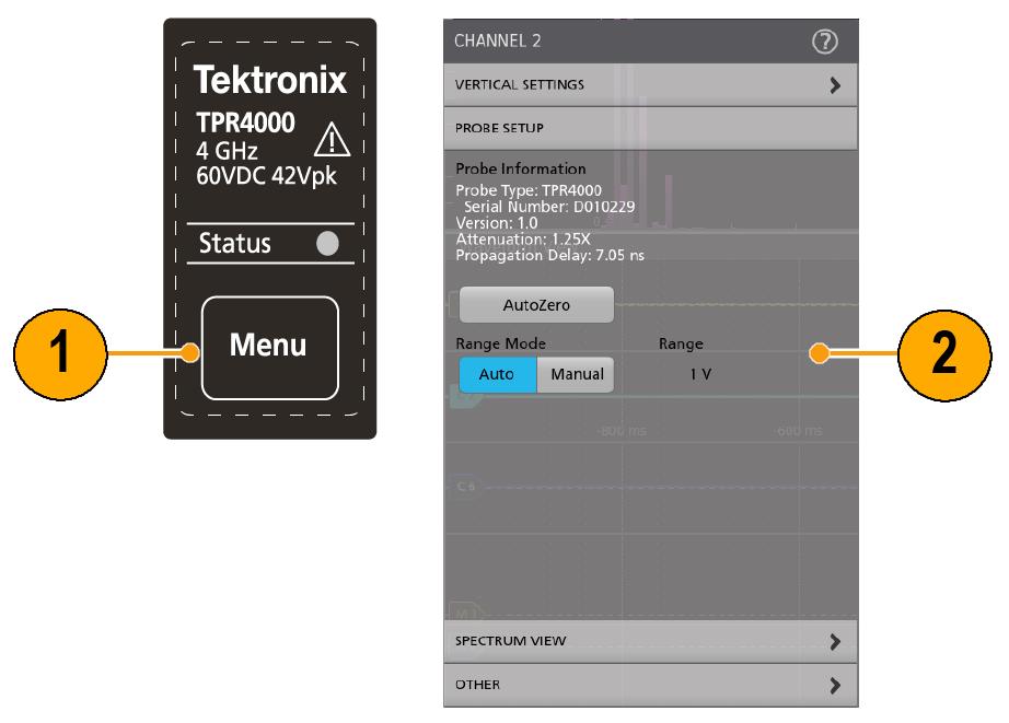
Menu button
Procedure
AutoZero
It is recommend to run AutoZero after the 20 minute warm-up period or when the operating temperature of the probe changes by ±5 °C.
Procedure
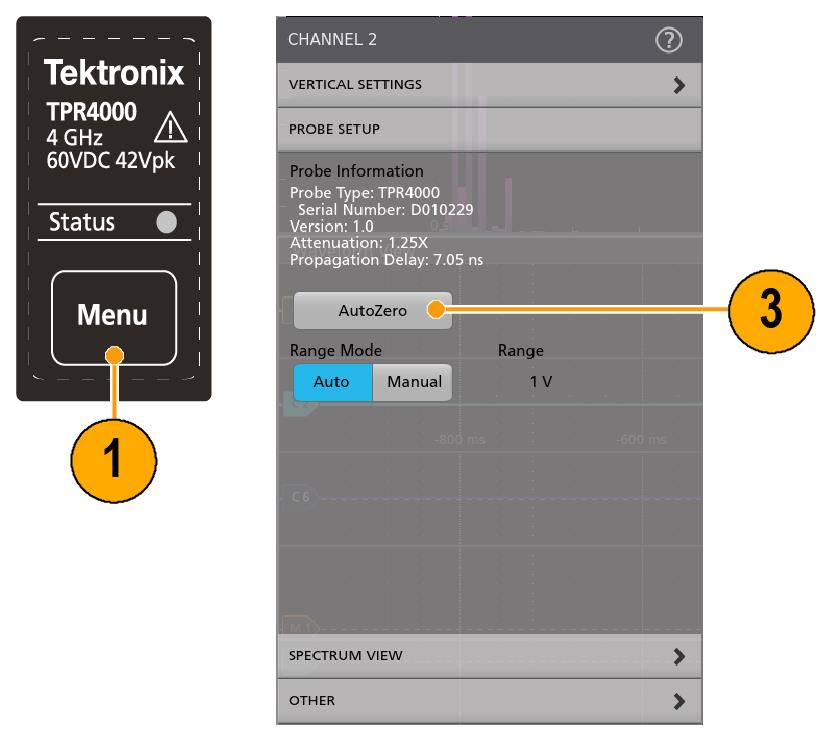
- Press the Menu button to display the Probe Setup menu on the instrument.
- Short the probe tip to ground.
- Press the AutoZero button on the instrument to run AutoZero.
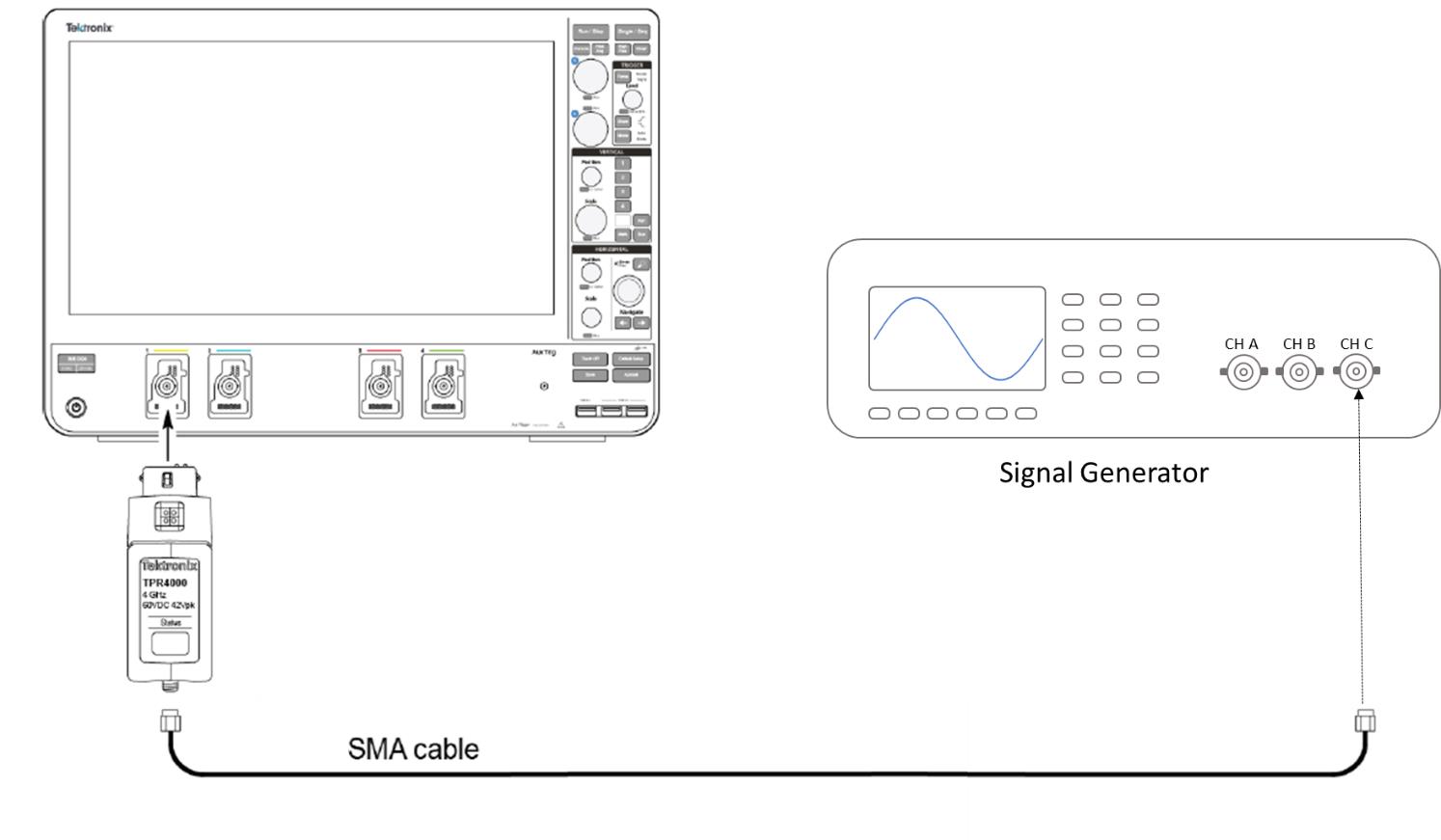
Functional check
Use the following procedure to check that your probe is functioning properly. To verify that your probe meets the warranted specifications, refer to the Performance Verification procedures.
Before you begin
| Description | Performance requirement | Recommended equipment |
|---|---|---|
| Oscilloscope | TekVPI Interface | DPO7000 Series, 3 Series MDO, 4 Series MSO, 5 Series MSO, 6 Series MSO |
| SMA cable | 1.3 m cable, SMA male-to-SMA male, 50 Ω | Cable included in standard accessory kit (TPR4KIT) |
| Sine wave generator | Frequency: 10 Mhz | - |
| Amplitude: 1 Vpp, Offset 1 Vpp |
Procedure
Required instrument software versions
The probe may operate with older versions of instrument software. However, older software versions than those listed are not guaranteed to provide full probe functionality.
| Instrument | Required software version |
|---|---|
| 5 and 6 Series MSO | 1.12.5 |
| MDO3000 | 1.27462 |
| MDO4000C | 1.09354 |
| MSO/DPO5000B | 10.8.3.3 |
| DPO7000C | 10.8.3.3 |
| DPO70000C/DX/SX | 10.9.1 |
Probe compatibility
Due to software incompatibilities between the TPR1000 and TPR4000 probes and some instrument models, the accuracy of probe measurements is reduced when the oscilloscope is used in vertical scale settings less than 2 mV/division. For all other vertical scale settings, the specified accuracy of the probe is maintained.
- MDO4000C
- MDO4000B
- MDO4000
- MDO3000
When you connect a TPR1000 or TPR4000 probe to one of the oscilloscopes listed above, the warning message shown below appears. If you want to proceed with using the probe with one of these oscilloscopes, press the Menu Off button on the oscilloscope to dismiss the message.
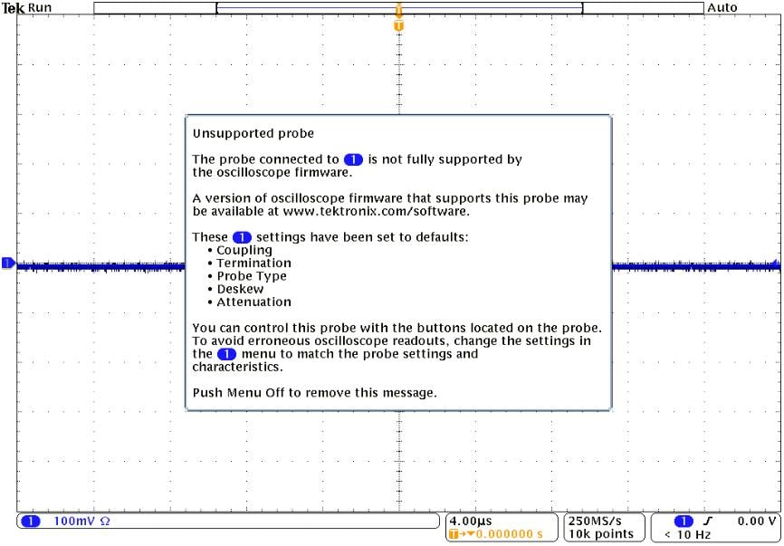
The oscilloscope will allow you to change the vertical scale setting below 2 mV/div without generating a warning message.
Probe input
The probe is electrically protected against static voltage. However, applying voltages above its design limits may damage the probe tip amplifier.
The probe head amplifier used by the probe has a limited linear operating range. To keep the input linearity error within specification, you must limit the signal input voltage to ±1 V.

Probe offset
Use the following instructions for setting the probe offset.
Before you begin
See your oscilloscope user manual for specific instructions on using the offset control.
About this task
The probe offset is adjustable for operation within the linear range of the probe, and to increase the sensitivity of the probe at higher DC measurement voltages. Using the offset to cancel DC signal components enables optimal probe performance.
Procedure
- Set the probe offset equal to the expected nominal DC value of the source you are connecting to.
- Set the vertical scale to 500 mV/div.
- Connect the probe to the circuit.
- Change the volts/div setting to the desired range, adjusting the offset as needed to keep the signal in the center of the screen.
Results
The probe has a ±60 V offset range. The linear operating range is ±1 V. When you adjust the probe offset with no signal applied to the probe input, the output range is ±1 V, (the linear operating range of the probe), not the ±60 V offset range of the probe. However, when you apply up to ±60 V to the probe input, the probe offset control can zero this offset.
If the signal on the screen displays an offset that is either 1 Volt higher or lower than expected, check to make sure the DUT is connected and operating. This is a result of the input to the LF amplifier being clamped at one extreme of the dynamic range when no input is present.
Connect MMCX accessories
The following describes how to connect to MMCX accessories.
Gently insert the MMCX end of the cable into one of the following accessories: micro-coax tip, solder flex tip, u.fl adapter, or MMCX to square pin Y-lead adapter, until you feel the connector engage. To remove an accessory, gently pull from the MMCX connection point, being careful to only grip the knurled metal area of the connector.
Connect solder-in accessories
The following describes how to connect to solder-in accessories.
There are two types of solder-in accessories, micro-coax and flex tips.
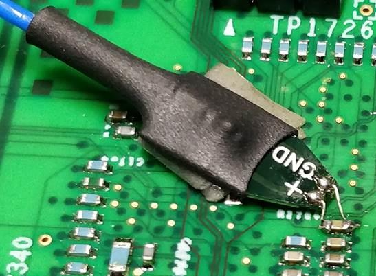
Micro-coax tip
For convenient first-time use, the solder micro-coax tips are shipped pre-trimmed and ready to be soldered to the test point. You can reuse a tip by removing the tip from the solder joint and then trimming the wire insulation back to expose the center pin and ground shield on the tip cable.
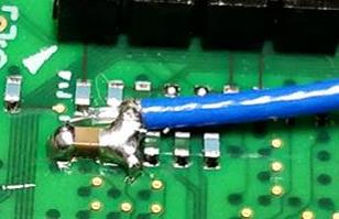
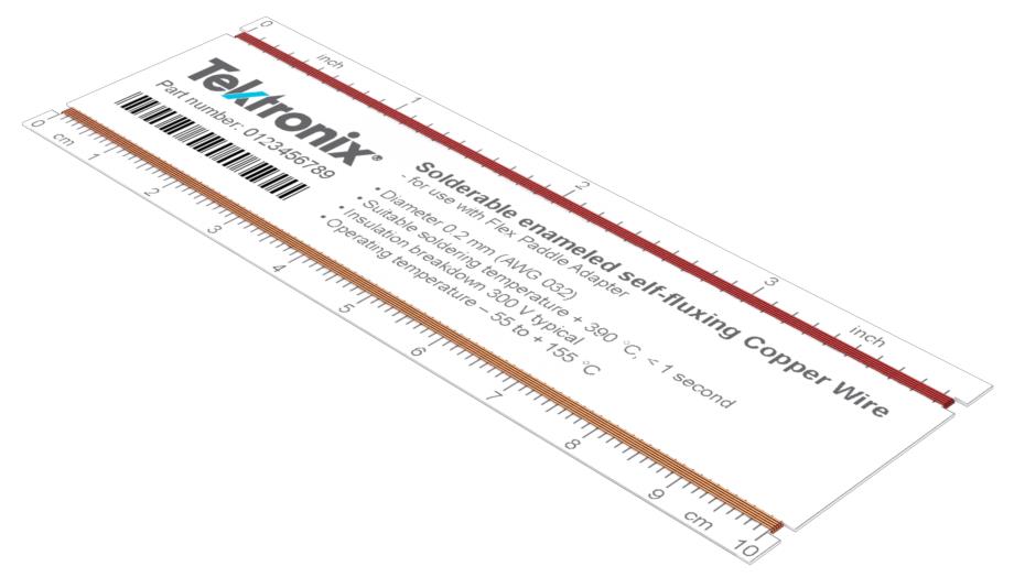
Flex tip
To attach the solder flex tip, first solder the enameled self-fluxing copper wire (standard accessory) to the test point. Feed the wire through the vias on the end of the flex tip, and then apply a small amount of solder to the vias to attach the wire to the tip.
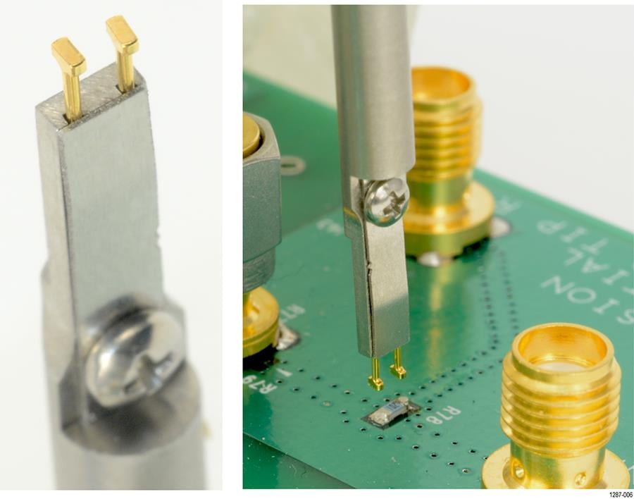
Using the solder-pin installation tool
The following describes how to install the solder pins using the supplied soldering-aide tool.
Before you begin
The supplied set of solder pins are intended to be installed on DUT circuit boards and used with the supplied MMCX to square-pin adapter.
The solder pins are extremely small and can be challenging to handle. It is recommended to use tweezers and a magnifying tool when installing pins on a circuit board.
Procedure
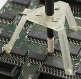
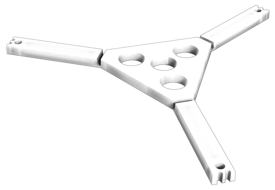
Using the tripod
The tripod probe support adds stability to square-pin mounted test points.
For more stability, use glue to attach the tripod legs to the DUT circuit board.
Using the optional browser
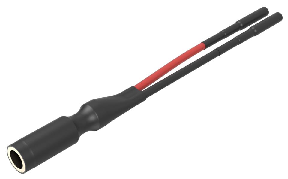
The optional browser kit contains the following parts: up to 1 GHz browser probe, square pin Y-lead adapter, micro-SMD clip, three ground leads, and four replacement probe-tip pins.
| WARNING:To prevent injury to the operator or damage to the probe, oscilloscope, and DUT, do not touch the probe ground to any point that is not at the same potential as the chassis ground of the oscilloscope. The probe ground must be connected to the same potential as the chassis ground of the oscilloscope. |
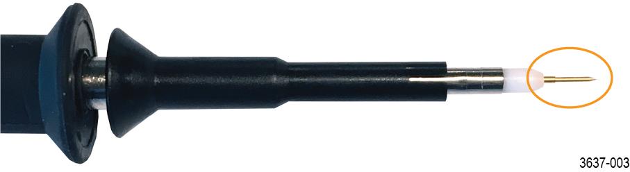
Installing ground leads
To obtain accurate measurements, always attach a ground lead to the probe tip before making measurements. It is recommended that you use the shortest ground lead that will function in your electrical application. The following illustration shows the browser probe tip, the tip cover, and the three types of grounds leads supplied with the browser.
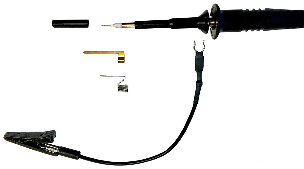
- To install the spring ground lead, slide the ground lead over the probe tip until it seats around the metal part of the probe-tip housing.
- To install the alligator ground lead, slide the ground lead prongs over the exposed metal between the plastic probe-tip sections.
- To install the blade ground lead, locate the slot in the probe-tip housing as shown below. Slide the ground lead over the probe tip until the blade slides into the slot.
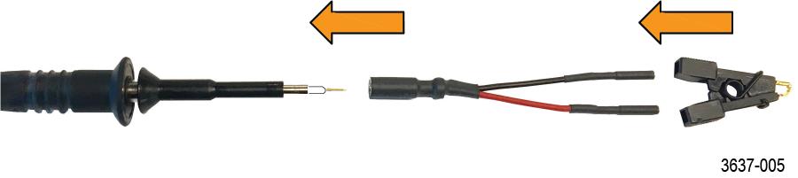
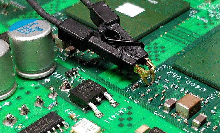
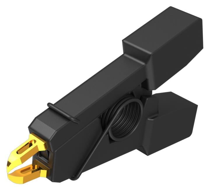
Connecting the Y-lead adapter and micro-SMD clip
The browser kit includes a Y-lead adapter and a micro-SMD clip that connect as shown below. The Y-lead adapter can also connect to square pins.
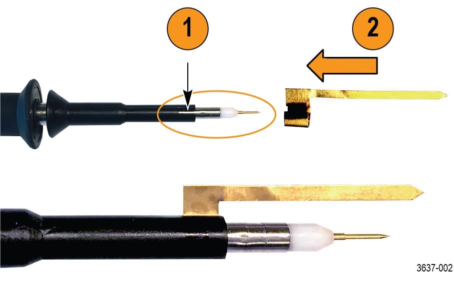
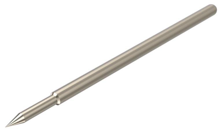
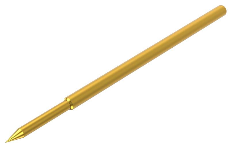
Replacing browser-tip pins
To remove the browser-tip pin, use pliers to grasp the pin and gently pull it out of the tip housing. To install a new browser-tip pin, select between a solid (silver colored) or spring-loaded (gold colored) pin, and then use pliers to gently insert the pin into the browser-tip housing until you feel the pin press against the bottom of the housing.
Ground lead length
When you are probing a circuit, you should always use as short a ground lead as possible between the probe head and circuit ground.
The following illustration shows the effects of lead length on waveform distortion.
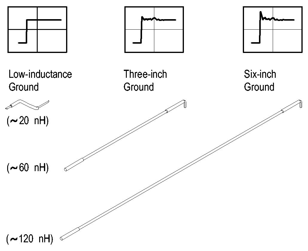
The series inductance added by the probe tip and ground lead can result in a resonant circuit; this circuit may cause parasitic ringing within the bandwidth of your oscilloscope.
Ground lead inductance
When you touch your probe tip to a circuit element, you are introducing a new resistance, capacitance, and inductance into the circuit.
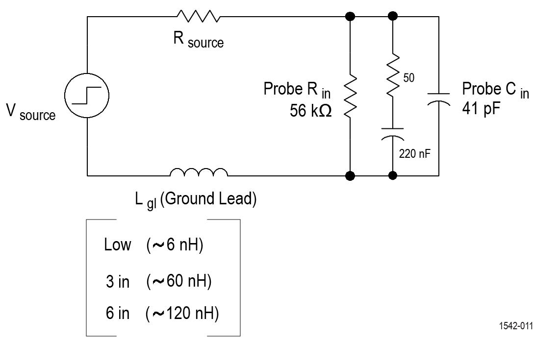
You can determine if ground lead effects may be a problem in your application if you know the self-inductance (L) and capacitance (C) of your probe and ground lead. Calculate the approximate resonant frequency (f0) at which this parasitic circuit will resonate with the following formula.
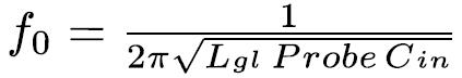
The equation shows that reducing the ground lead inductance will raise the resonant frequency. If your measurements are affected by ringing, your goal is to lower the inductance of your ground path until the resulting resonant frequency is well above the frequency of your measurements.
The low-inductance ground contacts described in Accessories can help you reduce the effects of ground lead inductance on your measurements.
Accessories
Each probe is shipped with one TPR4KIT accessory kit containing the following items.
| Item | Image |
|---|---|
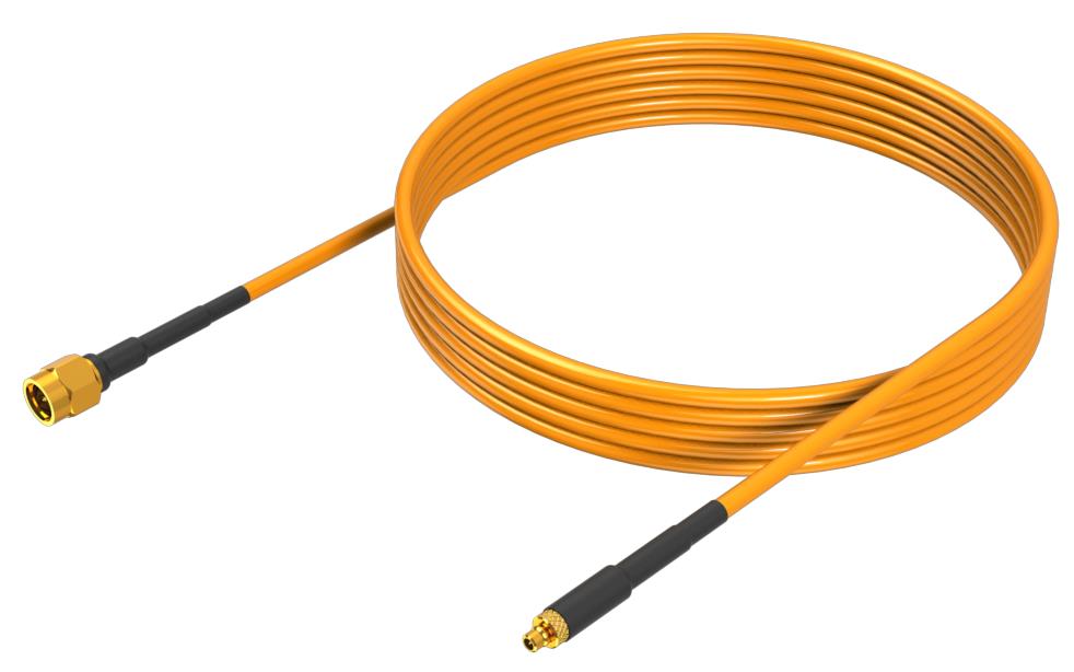
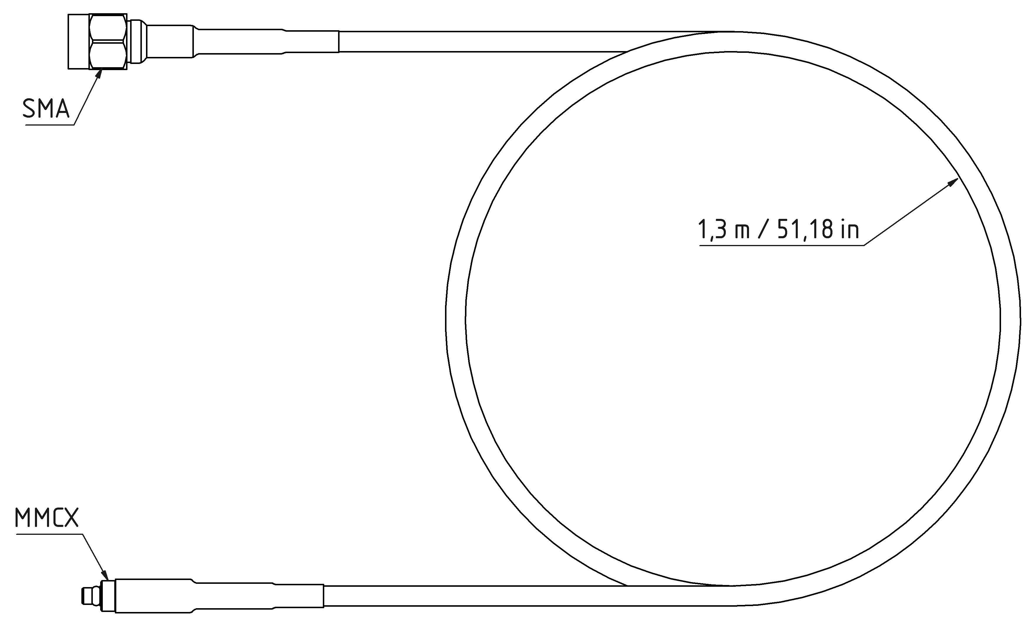
| 1.3 m cable, SMA male-to-MMCX male, 50 Ω |
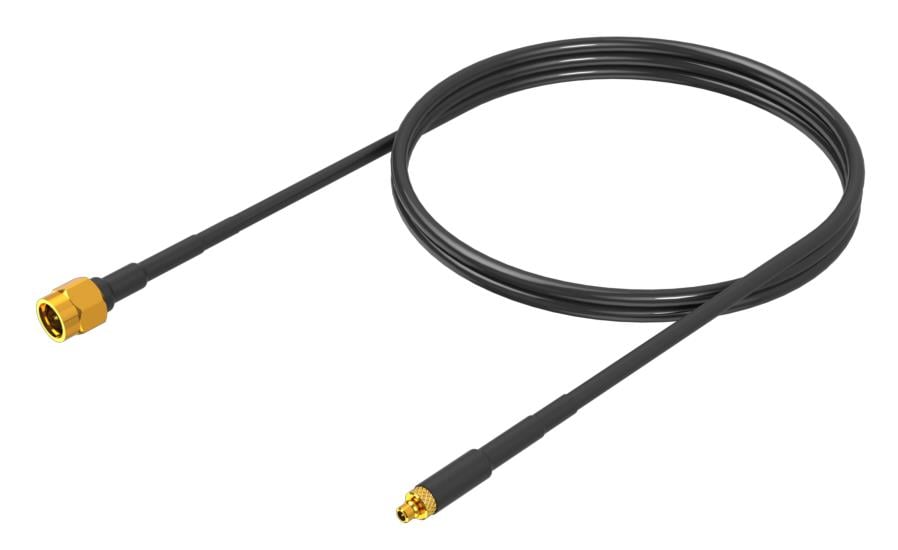 |
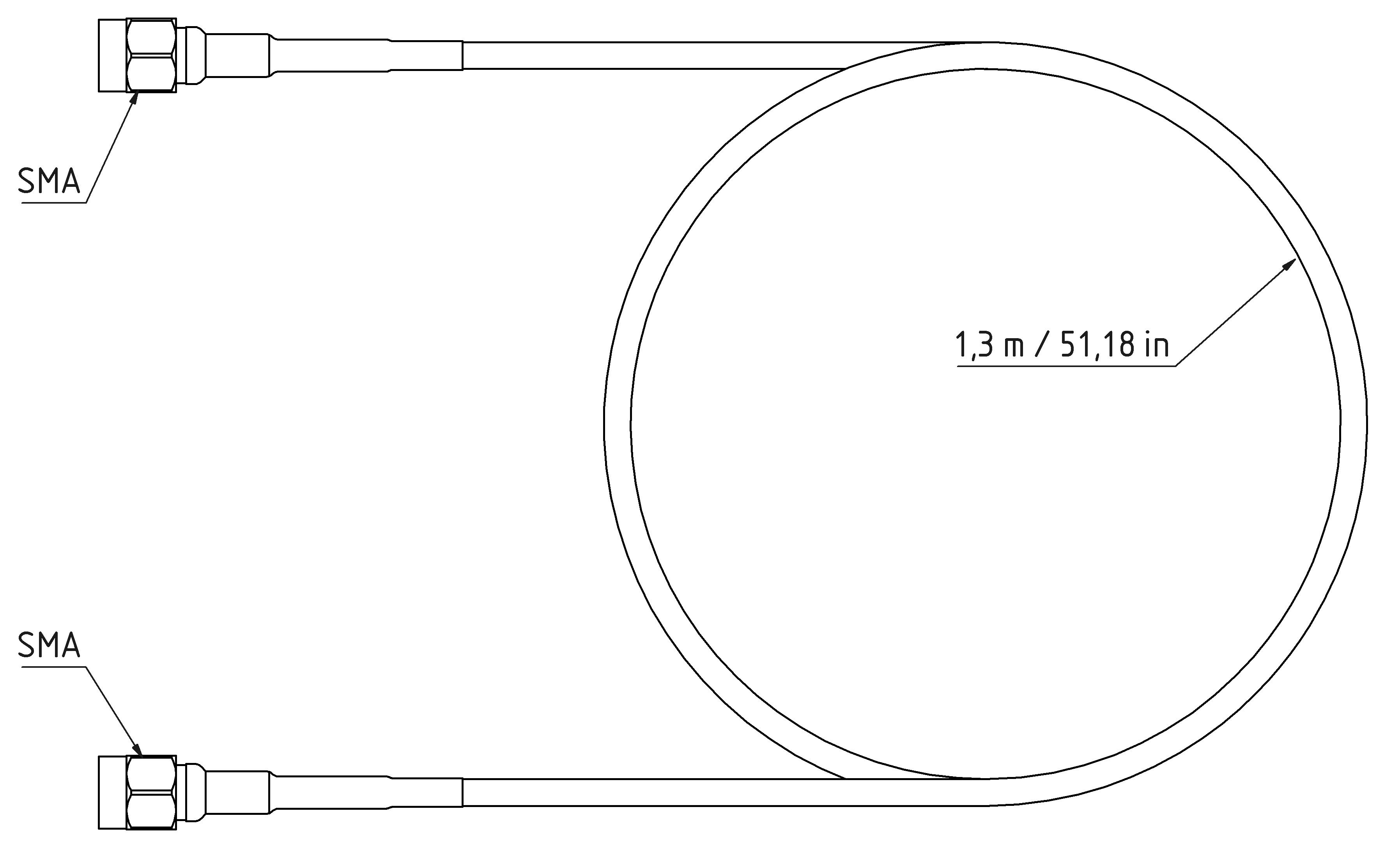
| 1.3 m cable, SMA male-to-SMA male, 50 Ω |
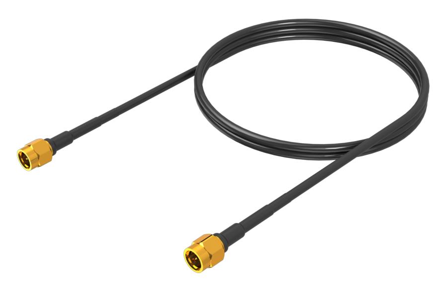 |
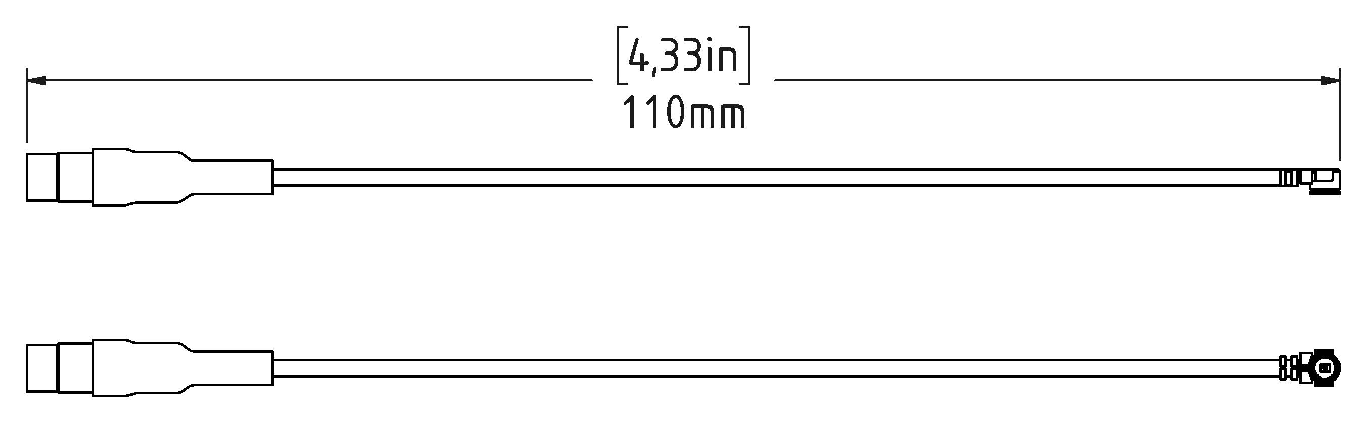
| Y-lead adapter, MMCX female-to-0.8 mm sockets |
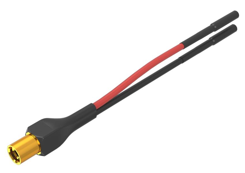 |
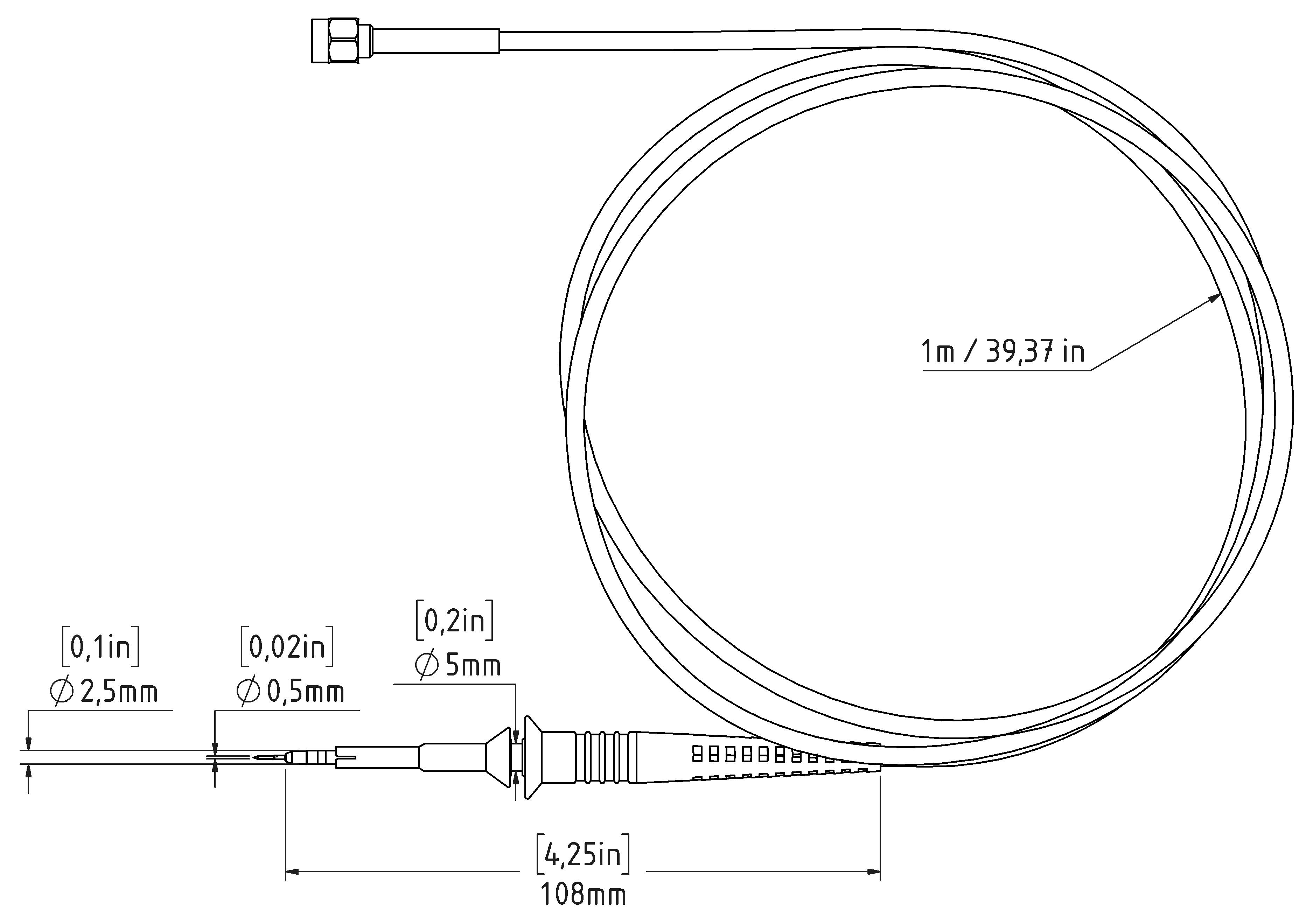
| Adapter cable, MMCX female-to-U.FL female, 50 Ω |
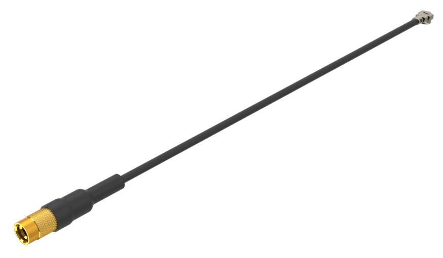 |
| Adapter, MMCX female-to-square pin (0.062 centers) | 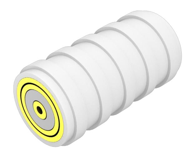 |
| DUT interface solder pins, set of 20 |
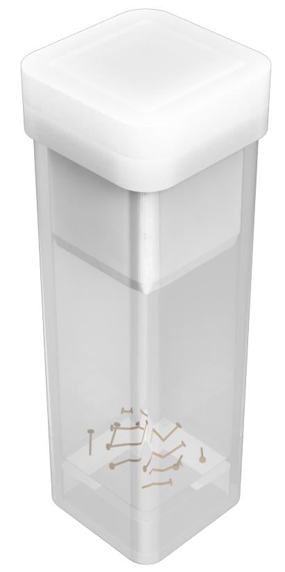 |
| Soldering aide tool, 0.062 solder pins over SMT |  |
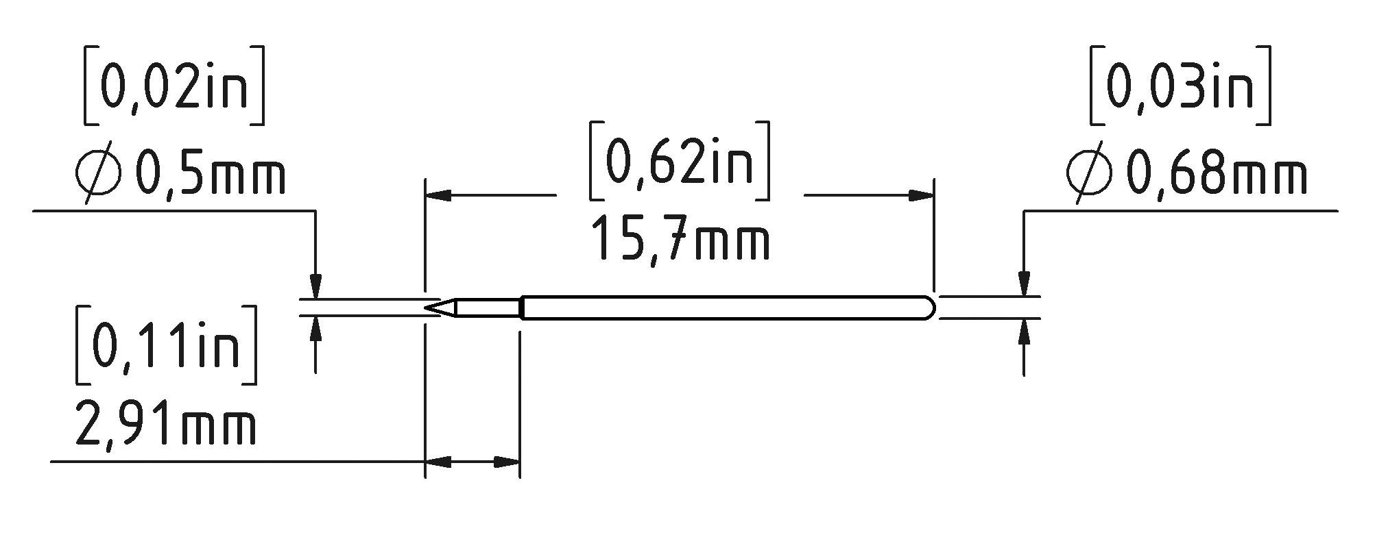
| Solder-in cable adapter, MMCX female-to-solder micro-coax tip, 50 Ω, set of 3 |
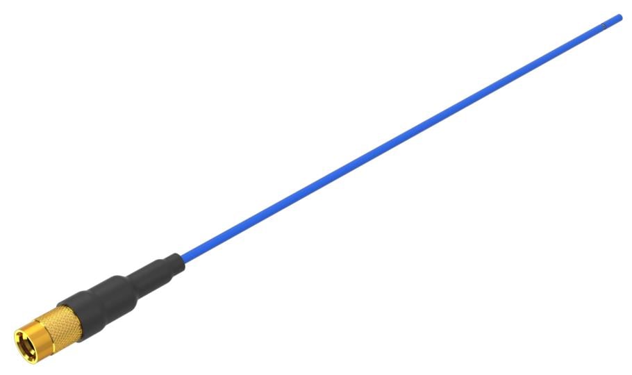 |
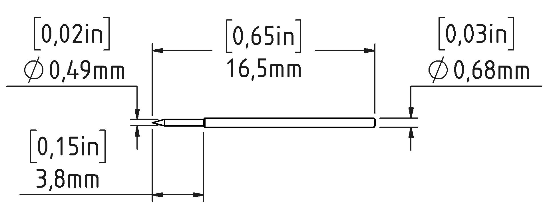
| Solder-in cable adapter, MMCX female-to-solder flex-paddle tip, 50 Ω, set of 3 |
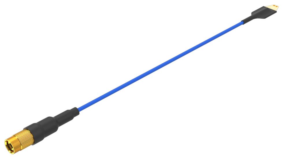 |
| Wire card, solderable enameled self-fluxing copper wire (for use with the solder-in tips) |
 |
| Probe tip tripod support (with living hinge) |
 |
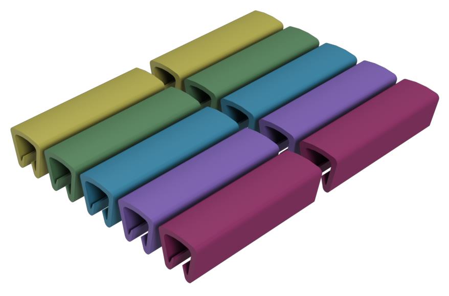
| Marker bands, set of 5 (for probe identification) |
 |
Optional high-temperature accessory kit
The optional TPR4KITHT high-temperature accessory kit contains the following items.
| Item | Image |
|---|---|
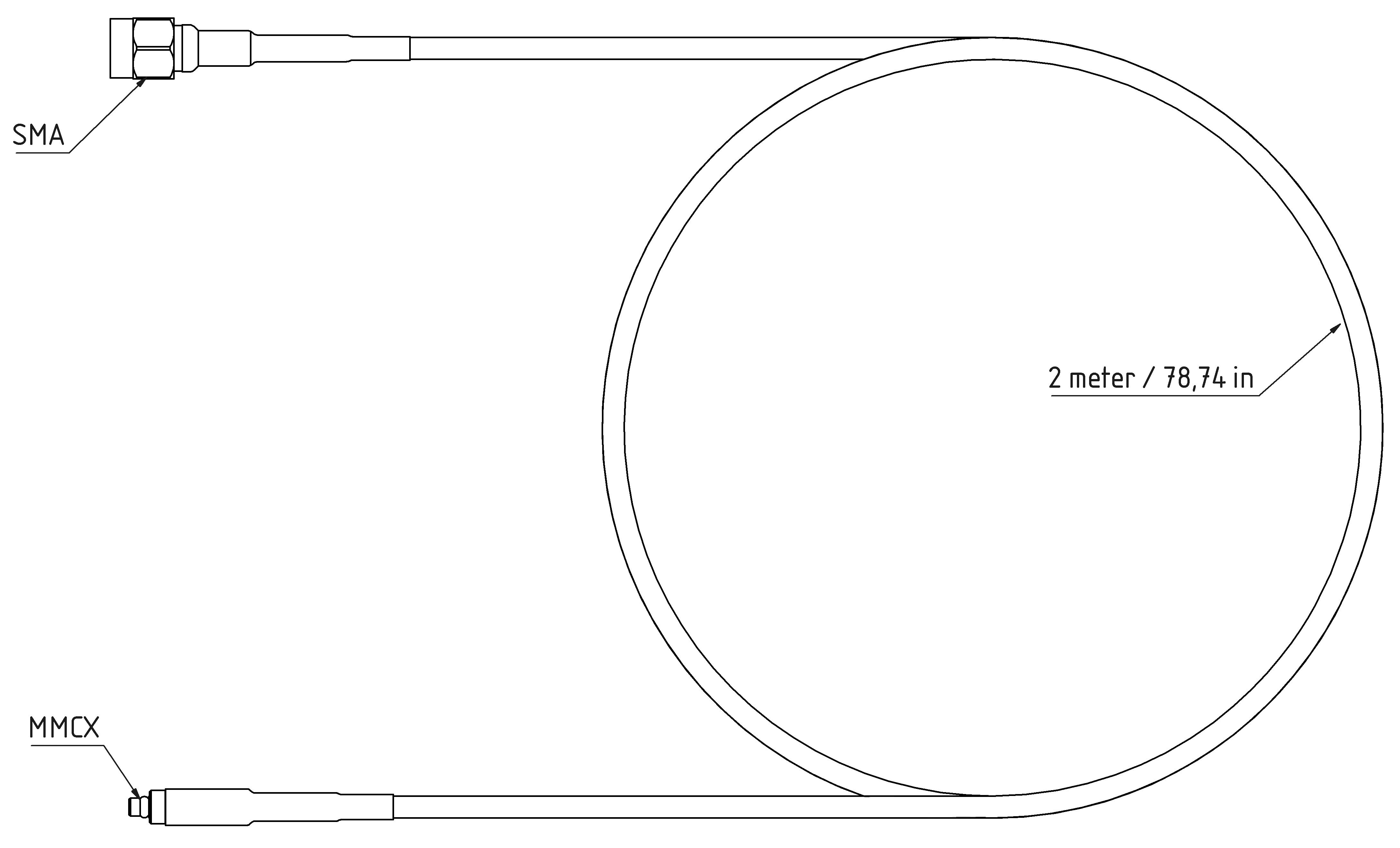
| 2 m high-temperature cable, SMA male-to-MMCX male, 50 Ω |
 |
| Solder-in cable adapter, MMCX female-to-solder micro-coax tip, 50 Ω, set of 3 |
|
| Solder-in cable adapter, MMCX female-to-solder flex-paddle tip, 50 Ω, set of 3 |
|
Optional 1 GHz browser accessory kit
The optional TPRBRWSR1G accessory kit contains the following items.
| Item | Image |
|---|---|
| Browser |
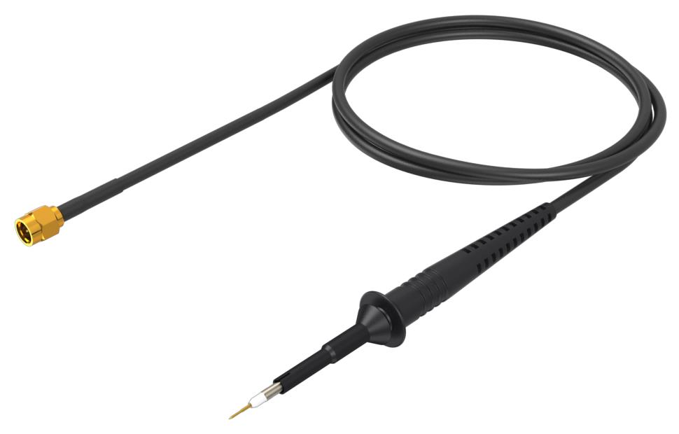 |
| Ground leads (blade, 0.5 mm spring, 15 cm alligator) |
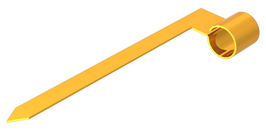 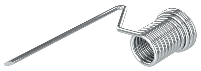 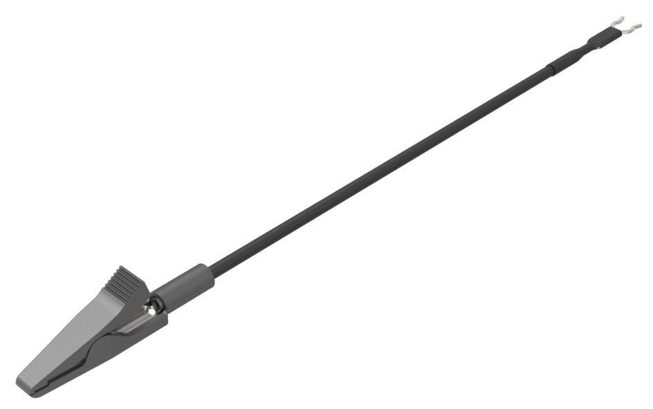 |
| Y-lead adapter, browser tip-to-0.8 mm sockets |
 |
| Micro-SMD clip |
 |
| Replacement 0.5 mm browser tips (2 solid tips, 2 spring tips) |
  |
Optional solder-in micro-coax tip accessory kit
The optional TPR4SIACOAX accessory kit contains the following items.
| Item | Image |
|---|---|
| Solder-in cable adapter, MMCX female-to-solder micro-coax tip, 50 Ω, set of 3 |
|
Optional solder-in flex-paddle tip accessory kit
The optional TPR4SIAFLEX accessory kit contains the following items.
| Item | Image |
|---|---|
| Solder-in cable adapter, MMCX female-to-solder flex-paddle tip, 50 Ω, set of 3 |
|
Specifications
The specifications apply to both the TPR1000 and TPR4000 probes unless noted otherwise.
- The probe has been calibrated at an ambient temperature of 23 °C ±5 °C.
- The probe is connected to a host instrument with an input impedance of 50 Ω.
- The probe and oscilloscope must have a warm-up period of at least 20 minutes and be in an environment that does not exceed the limits described.
- The Signal Path Compensation (SPC) has been run on the oscilloscope before testing the probe specifications.
Warranted characteristics
Warranted characteristics describe guaranteed performance within tolerance limits or certain type-tested requirements.
Warranted characteristics that have checks in the Performance Verification section are marked with the ✔ symbol.
| Characteristic | Description |
|---|---|
| DC attenuation | 1.25x |
| ✔ DC attenuation accuracy | <±1% within 80% of DC dynamic range |
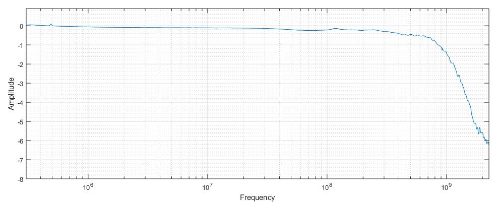
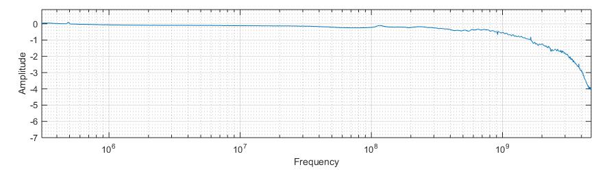
| ✔ Analog bandwidth (SMA configuration) | 1 GHz (TPR1000) |
| 4 GHz (TPR4000) | |
| DC input dynamic range | >±1 V |
| ✔ Offset scale accuracy | (2% of setting value + 2.5 mV max) |
| Typical value is ±(0.1% + 2.5 mV) after SPC and Probe Zero |
Typical characteristics
Typical characteristics describe typical, but not guaranteed performance.
| Characteristic | Description |
|---|---|
| DC input resistance | 50 kΩ |
| Return loss (50 Ω reference impedance) | Maximum: -12 dB between 10 MHz and 1 GHz (TPR1000) |
| Maximum: -12 dB between 10 MHz and 4 GHz (TPR4000) | |
| DC to AC impedance crossover frequency | 300 Hz |
| DC to AC gain matching | ±1% |
| Risetime (small signal, 20% to 80%) | 282 pS (TPR1000) |
| 88 pS (TPR4000) | |
| Risetime (small signal, 10% to 90%) | 408 pS (TPR1000) |
| 128 pS (TPR4000) | |
| Step Response Long Term Aberrations | <1% of final value after 50 µS |
| Delay time (compensation box only) | 565 ps ±20% (TPR1000) |
| 475 ps ±20% (TPR4000) | |
| Delay time for each accessory | 6.19 ns ±10% (1.3 m MMCX cable) |
| 9.47 ns ±10% (2 m MMCX cable) | |
| 494 pS ±20% (10 cm blue coax solder-in) | |
| 500 pS ±20% (10 cm Flex Paddle Adapter) | |
| 484 pS ±20% (U.FL to MMCX Adapter) | |
| 5.2 nS ±10% (Browser) | |
| Delay time (base configuration consists of 1.3 m SMA to MMCX cable + MMCX micro coax tip, TRPSIACOAX) | 7.12 nS |
| Noise | Typical: <25% RMS additive to oscilloscope at full bandwidth |
| Noise (probe only, DC to 20 MHz ) | Maximum: 220 µV p-p |
| Typical: 165 µV p-p into 6 series MSO | |
| Input common mode rejection | -20 dB 20 Hz up to probe bandwidth |
| Characteristic | Description |
|---|---|
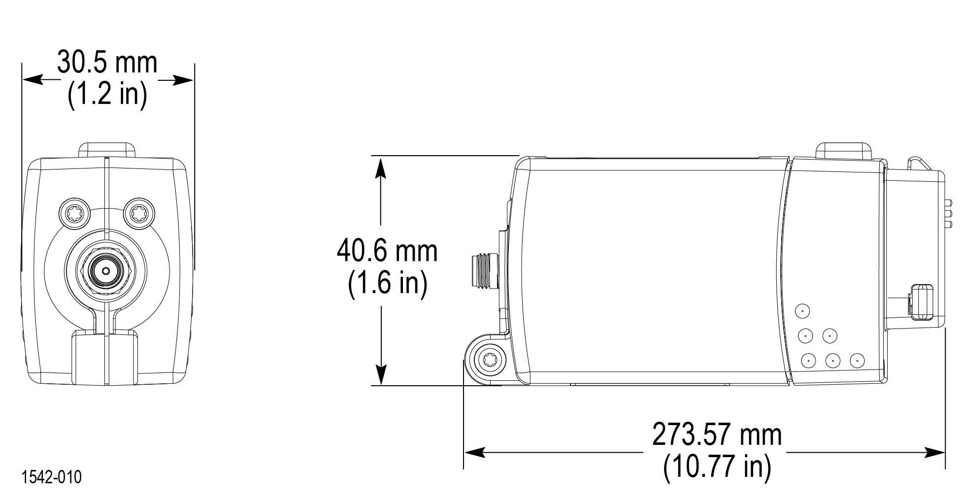
| Dimensions (compensation box) | 85.1 mm × 40.6 mm × 30.5 mm (3.4 in × 1.6 in × 1.2 in) |
| Packaged weight | 1.24 kg (2.7 lbs) |
Nominal characteristics
Nominal characteristics describe guaranteed traits, but the traits do not have tolerance limits.
| Characteristic | Description |
|---|---|
| Compatibility | Oscilloscopes equipped with the TekVPI interface |
| Instrument coupling | DC, LF-Reject |
| Input offset requestable range | ±60 V |
| Non-destructive input voltage range (AC frequency above 10 kHz) | 2.5 VRMS, with peaks ≤±20 V (DF 6.25%) |
| Input connector on compensation box | SMA-female jack |
| Output connector on cable | SMA-male plug |
| DUT connector on standard cable | MMCX-male plug |
| DUT connector on optional cable | SMA-male plug |
| SMP-female jack | |
| Insulation voltage rating | ±30 V RMS (AC) |
| ±42 V Peak (pk-pk) | |
| ±60 V DC (DC) |
Accessory characteristics
Specifications for the TPR1000 and TPR4000 accessories are either warranted and typical characteristics.
| Characteristic | Description |
|---|---|
| TPR4SIAFLEX and TPRSIACOAX (typical) | 1 GHz (TPR1000) |
| >3.5 GHz (TPR4000) | |
| SMA to SMA cable (warranted) | 1 GHz (TPR1000) |
| 4 GHz (TPR4000) | |
| MMCX to U.FL adapter (typical) | 1 GHz (TPR1000) |
| >2 GHz (TPR4000) | |
| MMCX to square pin adapter (typical) | 1 GHz (TPR1000) |
| 1 GHz (TPR4000) | |
| 2 M high temperature SMA to MMCX cable (typical) | 1 GHz (TPR1000) |
| >2 GHz (TPR4000) |
| Item number | Dimensions |
|---|---|
| Rigid Browser Tip |
 |
| Pogo Browser Tip |
 |
| Browser |
 |
| Browser Spring Ground |
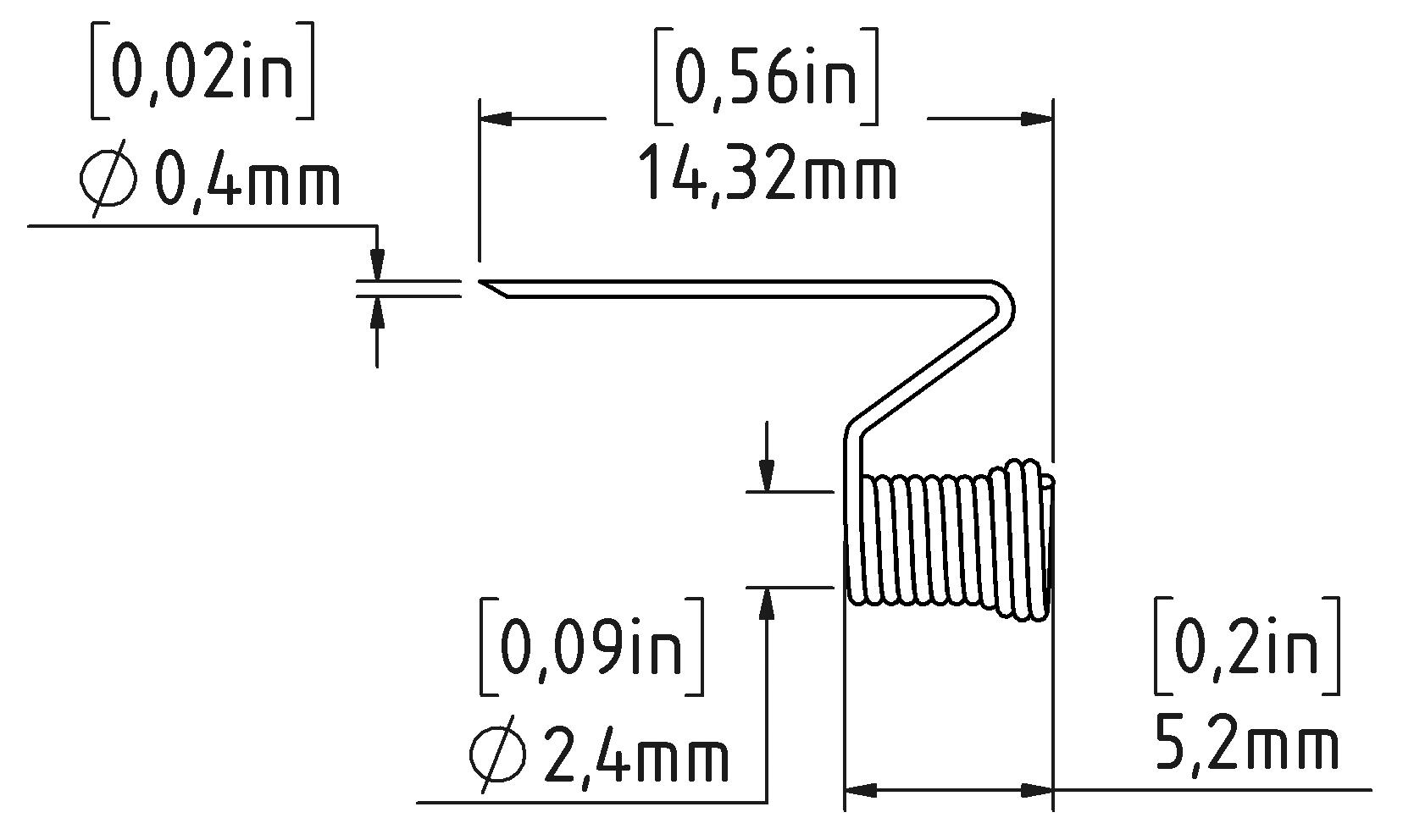 |
| Browser Blade Ground |
 |
| Browser Alligator Ground |
 |
| TPRSIACOAX |
 |
| TPRSIAFLEX |
 |
| MMCX to U.FL adapter |
 |
| 1.3 m SMA to MMCX Cable |
 |
| 1.3 m SMA to SMA Cable |
 |
| 2 m SMA to MMCX Cable |
 |
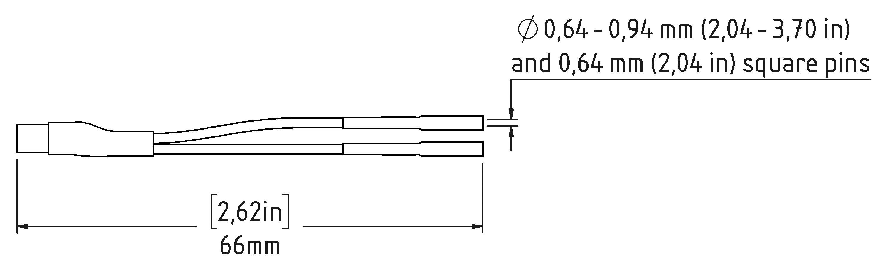
| Browser to Square-pin adapter |
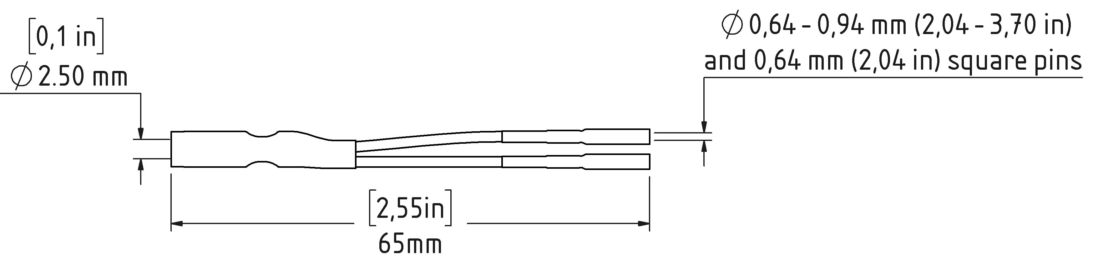 |
| MMCX to Square-pin adapter |
 |
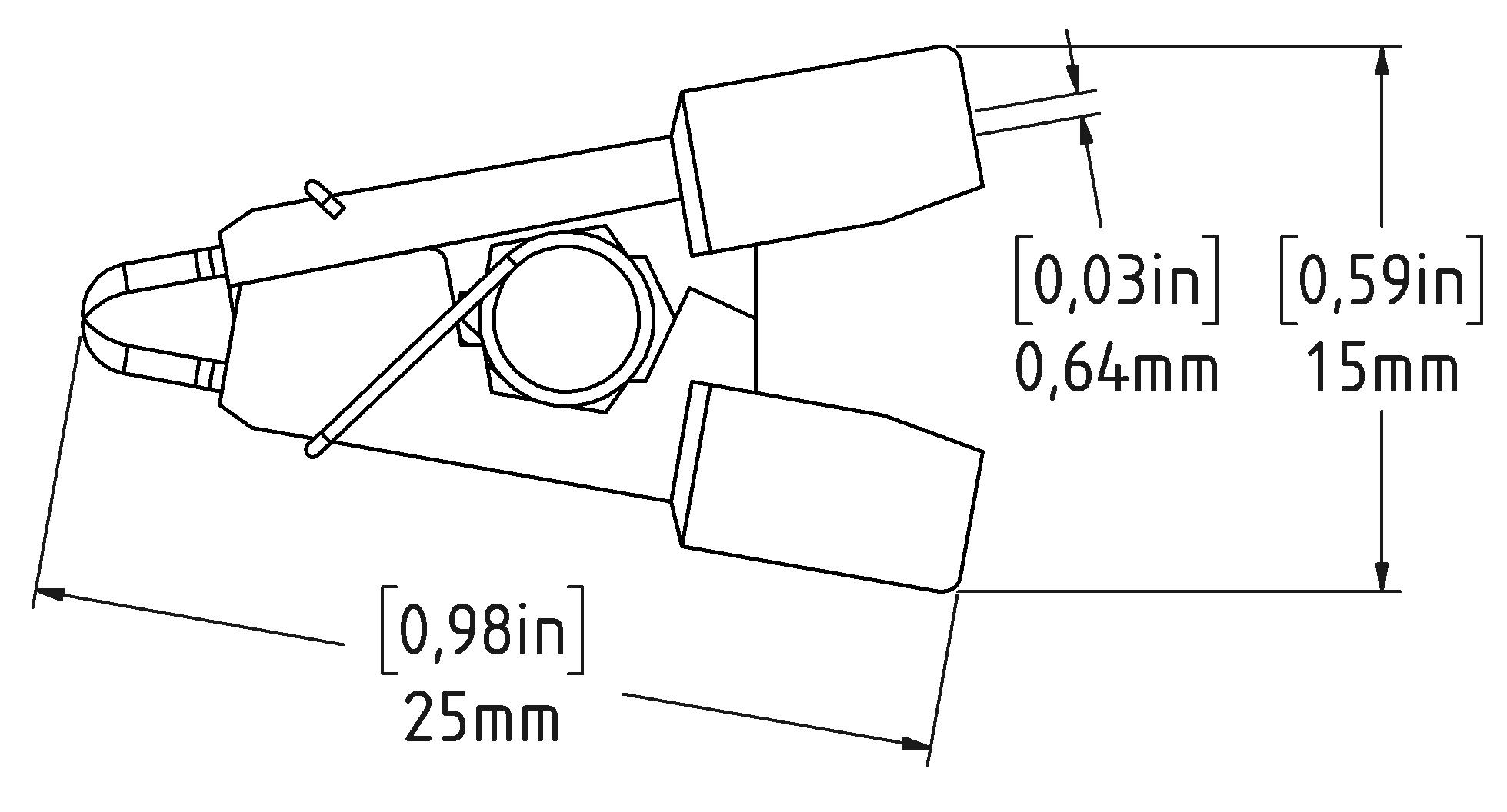
| SMT Component Clip |
 |
Performance verification
The procedures that follow verify the warranted specifications of the probe. The recommended calibration interval is one year. Perform the verification procedures in the order listed.
The following equipment is required for the performance verification procedures. The nine-digit part numbers (xxx-xxxx-xx) are Tektronix part numbers.
| Description and quantity | Performance requirement | Recommended example |
|---|---|---|
| Oscilloscope | TekVPI Interface | Tektronix 6 Series MSO, 8 GHz bandwidth option |
| DC calibration source | - | Keithley 2400 SMU |
| Digital multimeter (DMM) | Resistance, 0.1% accuracy | Keithley 2700 DMM |
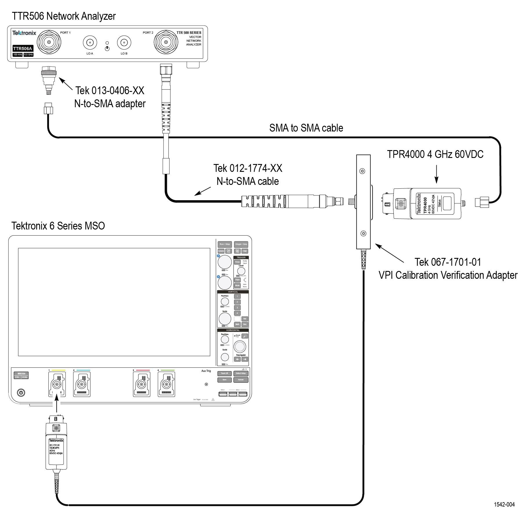
| Network Analyzer | - | Tektronix VNA TTR506, 067-1701-XX with Calibration kit BN533828 |
| TekVPI Calibration Verification adapter | TekVPI Interface | - |
| SMA to BNC adapter | SMA male to BNC female | 015-0554-XX |
| SMA to BNC adapter | SMA female to BNC male | 015-0572-XX |
| SMA to SMA adapter | SMA male to SMA male | 015-0551-XX |
| BNC-to-dual banana adapter (2) | - | 103-0090-XX |
| BNC cable (2) | 50 Ω, 0.76 m (30 in) length | 012-0117-XX |
| Feed-thru termination | 50 Ω, 1 GHz, ±0.5 Ù | 011-0049-XX |
| SMA cable for network analyzer | N to SMA-M 5 foot cable | 012-1774-XX |
| SMA adapter for network analyzer | Type-N male to Type-SMA female | 013-0406-XX |
| SMA torque wrench | 5/16-in, 7 in-lb. | - |
| SMA adapter wrench | 7/32-in | - |
Equipment setup
Use the following procedures to set up and warm up the equipment to test the probe.
- DC gain accuracy
- DC input dynamic range
- Input offset range and scale accuracy
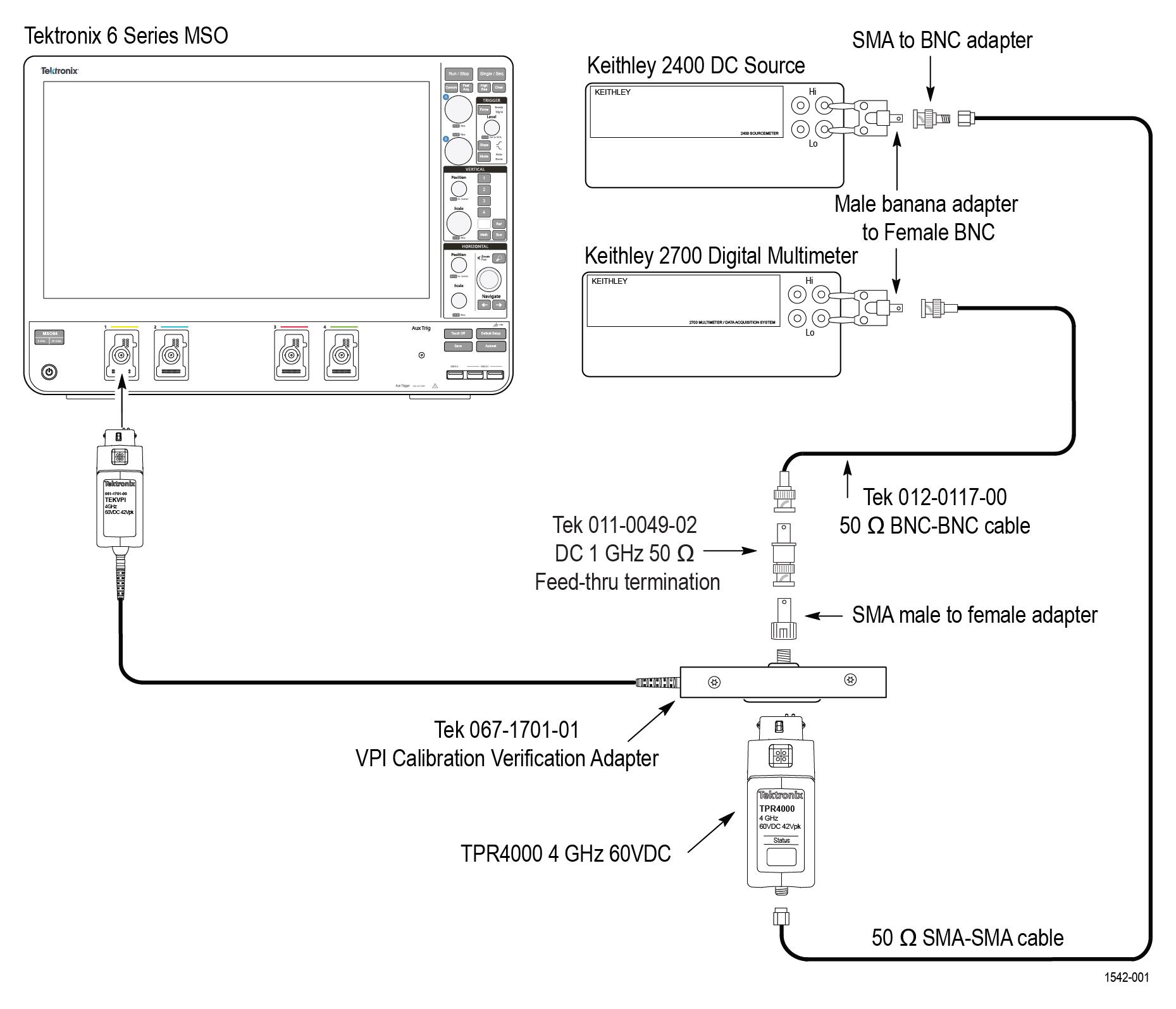
Use the analyzer setup diagram for the analog bandwidth performance check.
Warm up the test equipment
- Turn on the TekVPI oscilloscope.
- Connect the TekVPI Calibration/Verification adapter to the oscilloscope.
- Connect the probe to the TekVPI Calibration Verification adapter and verify that the Status LED on the probe turns green.
- Turn on the remaining test equipment.
- Allow 20 minutes for the equipment to warm up.
- Use the test record template to record the test results.
Test record
Use the test record to record the values of the performance verification checks.
| Probe Model/Serial Number: |
|
| Certificate Number: |
|
| Temperature: |
|
| RH %: |
|
| Date of Calibration: |
|
| Technician: |
|
| Performance test | Minimum | Measured / calculated | Maximum | |
|---|---|---|---|---|
| DC gain accuracy | 0.792 |
| 0.808 | |
| DC input dynamic range | –1 V |
| NA | |
| NA |
| +1 V | ||
| DC reject function | Pass/Fail |
| - | |
| Input offset range and scale accuracy | +12 V offset | -194 mV |
| 194 mV |
| +1 V offset | -18 mV |
| 18 mV | |
| –1 V offset | -194 mV |
| 194 mV | |
| –12 V offset | -18 mV |
| 18 mV | |
| Analog bandwidth | TPR1000 | -3 dB |
| NA |
| TPR4000 | -3 dB |
| NA | |
Check the DC gain accuracy
Use the following test to check the DC gain accuracy of the probe.
Before you begin
When using the DMM function in a Keithley SMU, turn on FILTER to reduce transient output values.
Procedure
Example
| Index | DC source voltage | Vout (measured) | Vout (linear fit) |
|---|---|---|---|
| –2 | –640 mV | –513 mV | –512 mV |
| –1 | –320 mV | –256 mV | –256 mV |
| 0 | 0 mV | 0.0009 mV | 0 mV |
| 1 | 320 mV | 258 mV | 256 mV |
| 2 | 640 mV | 515 mV | 512 mV |
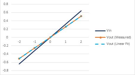
The gain slope can either be obtained by using a spreadsheet to calculate the linear regression of the points, or graphically by hand. To obtain the gain slope graphically, carefully plot each measurement point on a rectangular coordinate system, the X axis is the DC source voltage and the Y axis is the measured DC output value. Using a straight edge, draw a line through the points, minimizing the error between the line and each point. The gain slope is taken by the slope of the drawn line (rise in Y divided by run in X), and the zero point error taken at the point at which the line crosses the Y axis. The DC output value can be predicted by the following equation:

| Vout (linear fit) slope | Vin slope | Measured gain |
|---|---|---|
| 0.257 | 0.320 | 0.803125 |
Check the DC input dynamic range
Use the following test to check the DC input dynamic range of the probe.
Before you begin
When using the DMM function in a Keithley SMU, turn on FILTER to reduce transient output values.
Procedure
Check the input offset range and scale accuracy
Use the following test to check the input offset range and scale accuracy of the probe.
Procedure
Check the analog bandwidth
Use the following test to check the analog bandwidth of the probe.
About this task
Procedure
- Connect the test equipment as shown in the Analyzer setup diagram.
- Set the network analyzer to measure insertion loss (S21) in dB. Set the network analyzer to the following settings:
- Power Level: –10 dBm
- IF Bandwidth: 1 kHz
- Sweep Type: Linear
- Start Frequency: 300 kHz
- Stop Frequency: 6 GHz
- Number of points: 201
- Set scale factor: 1 dB
- Set up the network analyzer with a fresh 2-port SOLT calibration to the reference planes of the SMA side of network analyzer cable (port 2) and the SMA side of the SMA-to-N adapter (port 1).
- Place a marker on the S21 trace at the start frequency (300 kHz).
- Place a marker on the S21 trace at the probe bandwidth (1 GHz for TPR1000 or 4 GHz for TPR4000).
- Verify that the amplitude is greater than -3.97 dB (subtracting the 0.97 dB of probe attenuation range from the 3.97 dB target value yields the 3 dB limit).
- Record the result in the test record.
Maintenance
This section contains maintenance information for your probe.
| Note:There are no user replaceable parts within the probe. Refer to Accessories for a list of replaceable accessories for your probe. |
Cleaning
Protect the probe from adverse weather conditions. The probe is not waterproof.
| CAUTION:To prevent damage to the probe, do not expose it to sprays, liquids, or solvents. Avoid getting moisture inside the probe during exterior cleaning. |
Do not use chemical cleaning agents; they may damage the probe. Avoid using chemicals that contain benzine, benzene, toluene, xylene, acetone, or similar solvents.
Clean the exterior surfaces of the probe with a dry, lint-free cloth or a soft-bristle brush. If dirt remains, use a soft cloth or swab dampened with a 75% isopropyl alcohol solution. A swab is useful for cleaning narrow spaces on the probe, use only enough solution to dampen the swab or cloth. Do not use abrasive compounds on any part of the probe.
Returning instrument for service
Use the following instructions for returning your instrument for service.
When repacking the instrument for shipment, use the original packaging. If the packaging is not available or unfit for use, contact your local Tektronix representative to obtain new packaging.
If you need to return your instrument for repair or calibration, call 1-800-438-8165 or complete the form at tek.com/services/repair/rma-request. When you request service, have the serial number, firmware, and software version of the instrument.
If you want to see the warranty or service agreements on your products, or if you want to create your own service price estimate, visit our quick service quote site at tek.com/service-quote.
Help us improve our technical documentation. Provide feedback on our TekTalk documentation forum.