The SRQ feature of the GPIB bus provides hardware hand shaking between the GPIB controller card in the PC and the instrument. This allows synchronization between moving data to the PC with the state of the instrument without the need to use time delay functions.
Background
Whenever an instrument is being controlled from a PC to take measurements, at least two basic steps are involved:
1. Configure (setting up desired functions, channels, etc.) and initiate the measurements
2. Once the measurements are complete, bring back the data to the PC.
A common issue here is that after initializing the measurements, how do you know when the measurements are complete so that you can retrieve the data?
Depending on how time critical your application is, this issue may or may not be significant. One common way around this issue is to estimate the time it would take for x-number of measurements, and then use some type of time delay function or loop in the application program before fetching the data. However, this approach is subject to variability in processing speeds on different computers. What might be sufficient delay on a certain class of Pentium computer might not be long enough on a computer you purchase in the future.
When all the timing information such as various delays on the instrument, measurement speed (A/D conversion time) and various system configuration time are available, you can of course make a good estimate on how much time delay to set. Although by no means a robust approach, using an appropriate time delay will be sufficient if your application is not timing critical, or optimizing data transfer is not your concern.
However, many applications require optimized timing to achieve maximized throughput in overall system speeds or some simply want to take the guesswork out of programs. If that is the case, using the service request (SRQ) feature of the GPIB interface provides an alternative, more streamlined approach.
Important GPIB features
GPIB (IEEE-488.2) provides a system for reporting status and event information, which allows you to find out if the instrument has data to return, whether an error occurred, limit has been exceeded, etc. Typically, the reporting system consists of 8-bit register sets and queues (usually output and error queue). Please reference: “Status Structure” section of your instrument manual. Usually, each register set is made up of a condition register, an event register and an enable register. The condition register and event register are “read only” registers. They are constantly updated to reflect current operating conditions or events.
The enable register is the only type of register you can program (“read/write”). In the following discussion, we will manipulate this register to generate SRQ on the GPIB bus.
Without going into other details of GPIB features (IEEE-488.2), we should note that pin# 10 of GPIB is the Service Request (SRQ) line. This line is used by the talkers,
e.g. an instrument, to asynchronously request service from the controller (e.g. GPIB card in PC).Note:Since it is not the intention of this note to explain the detail status structure of the instrument, you are encouraged to reference to your instrument manual for more information. The following discussion assumes that you are somewhat familiar with the status structure of your instrument.
Generating the Service Request
Let’s assume that you want to gather x-number of measurements from your instrument. You don’t know how long your instrument will take to perform this task, so you want the instrument to generate a Service Request (SRQ) when the task is complete so that you can fetch the data. A common approach in this case is to store x-points of data in the instrument buffer and then to generate a SRQ when this buffer is full.
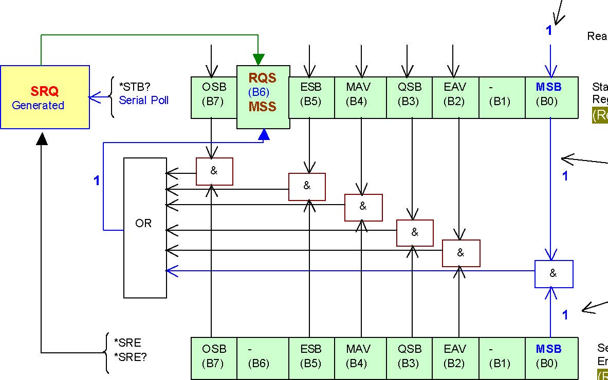
The following diagram shows the Status Byte and Service Request Enable Registers:

Status Byte and Service Request.
OSB = Operation Summary Bit
MSS = Master Summary Status
RQS = Request for Service
ESB = Event Summary Bit
Mav = Message Available
QSB = Questionable Summary Bit
EAV = Error Available
MSB = Measurement Summary Bit
& = Logical AND
OR = Logical OR
From the above diagram, you can see that to generate SRQ, RQS/MSS bit (B6) of the Status Byte Register must be set. If you perform serial poll while RQS/MSS bit is set (logic ‘1’), then SRQ will be generated on the GPIB bus.
It is important to recall that you can only program Enable Registers, which means you cannot directly write to the Status Byte Register. From the above register map, note that the RQS/MSS bit will be set:
1. our code sets a bit on the Service Request Enable Register, and
2. if the corresponding bit in the Status Byte Register is also set (by the instrument).
Since Service Request Enable Register is an Enable Register, we can set the bit directly using “*SRE y” command, where y is the weighted bit value in decimal. For example, using “*SRE 1” will set the MSB (B0) and “*SRE 8” will set the QSB (B3) of the Service Request Enable Register. “*SRE?” will return the current value of the Service Request Enable Register. For this discussion, let’s assume that we set MSB (B0) by writing “*SRE 1”.
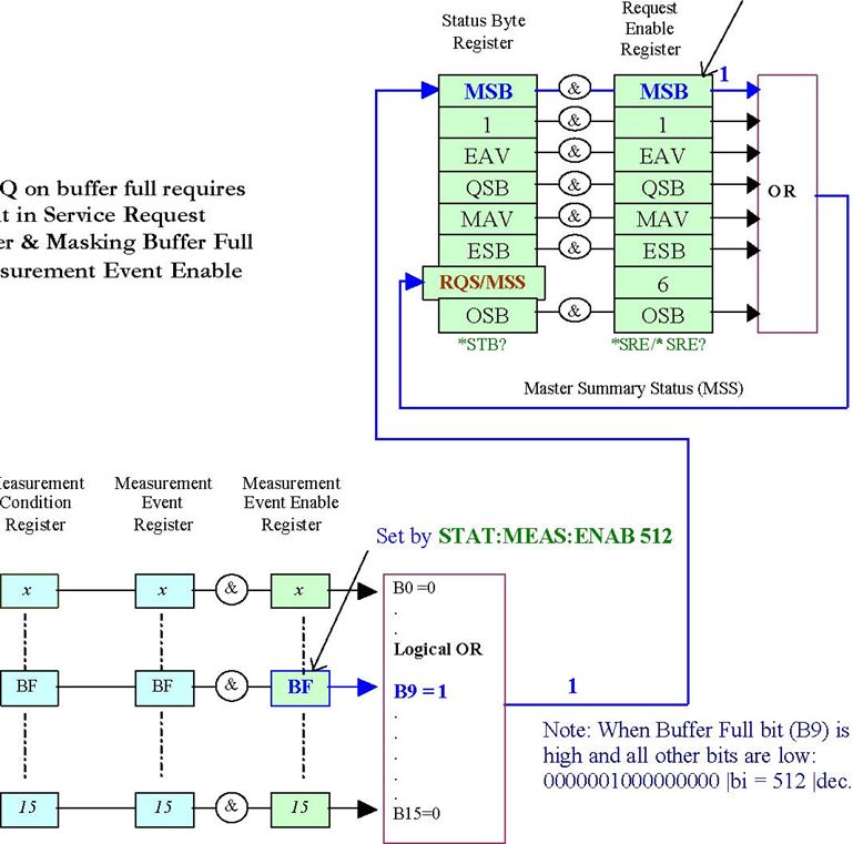
How do we configure the instrument to set the corresponding bit in the Status Byte Register when the buffer is full? The overall Status Register Structure below shows that MSB (B0) of Status Byte Register is being controlled by the Measurement Registers. Since we have “write” access to enable registers only, we need to set an appropriate bit in Measurement Event Enable register.


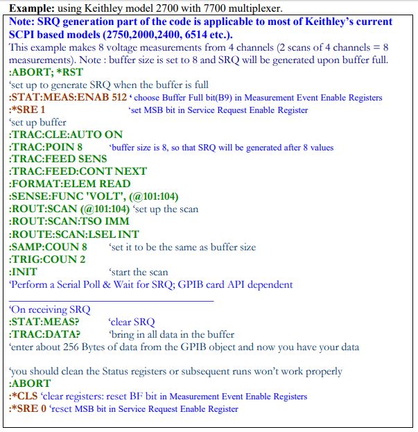
NOTE: the SCPI commands above would be used together with the commands of the GPIB card to send, enter or perform serial poll (IEEE-488.2).
SRQ is a feature of GPIB. Detection of SRQ through VISA interface (to GPIB) is possible as well. RS-232 or TCP/IP interfaces do not support SRQ.
Conclusion
SRQ feature of GPIB based instruments provides a convenient and optimum way to coordinate data transfer from the instrument to the PC as soon as the data are available. In fact, it can be an invaluable feature for applications that require tight timing synchronization.
Appendix A
Let’s discuss the more complex scenario. Suppose you want to enable generation of SRQ for more than one condition: Buffer Full, High Limit, and Low Limit.
As before, the corresponding bits in the Measurement Event Enable Register would need to be set by the controlling code. These three conditions correspond to bits 9, 2 and 1.
These three bits combine for a value of 518 (29 + 22 + 21 = 512 + 4 + 2 = 518). The
SCPI command would be :STAT:MEAS:ENAB 518
Now when any of the conditions occur, a value of 1 would be feed into the Measurement Summary Bit of the Status Byte Register. If the corresponding bit of the Enable Register has been set to a 1, then RQS (B6) will be set and the serial poll operation will detect the SRQ condition.
In contrast to the previous case, now you must determine which of the three conditions is responsible for the SRQ. To do this use the :STAT:MEAS:EVENT? command to query the Measurement Event register. This will return the value of that 8-bit register and clear it’s contents. A bit-wise compare on the returned value can determine which bit (9, 2 or 1) was responsible for the SRQ.


