Kontaktaufnahme
Live-Chat mit Tektronix-Vertretern. Verfügbar von 9 bis 17 Uhr CET Geschäftstage.
Kontaktieren Sie uns telefonisch unter
Verfügbar von 9 bis 17 Uhr CET Geschäftstage.
Download
Laden Sie Handbücher, Datenblätter, Software und vieles mehr herunter:
Feedback
User Defined Filter Tool
5 Series/6 Series B MSO Option 5-UDFLT/6-UDFLT Application Datasheet

In the broad sense, any system that processes a signal can be thought of as a filter. For example, an oscilloscope channel operates as a low pass filter where its 3 dB down point is referred to as its bandwidth. Given a waveform of any shape, a filter can be designed to transform it into a defined shape within the context of some basic rules, assumptions, and limitations.
Digital filters have some significant advantages over analog filters. For example, the tolerance values of analog filter circuit components are usually large, such that high-order filters are difficult or impossible to implement. With digital filters, high-order filters are easily realized.
The 5 Series and 6 Series MSO allow you to apply filters to math waveforms through a MATH Arbitrary function. The User Defined Filter (UDF) tool, (Option 5/6 UDFLT) takes this functionality a level deeper, providing more than MATH Arbitrary basic functions and adds flexibility to support standard filters and can be used for application centric filter designs.
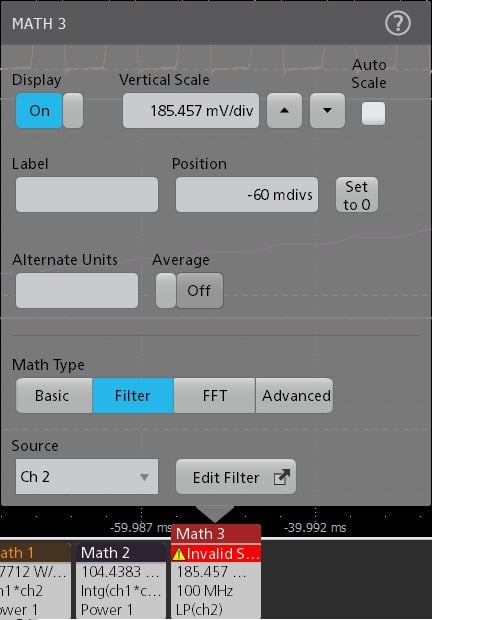
Supported filter types:
- Low-Pass
- High-Pass
- Band-Pass
- Band-Stop
- All-Pass
- Hilbert
- Differentiator
- Raised-Cosine
- Root-Raised-Cosine

Supported filter responses:
- Butterworth
- Chebyshev I
- Chebyshev II
- Elliptical
- Gaussian
- Bessel-Thomson
- Custom

General applications of filters
Low-Pass filters (LPF) are used to remove background and high-frequency noise. High-Pass filters (HPF) can be used to remove DC and low-frequency components. Both LPF and HPF are commonly used in high-speed serial and data communication applications. Band-Pass filters (BPF) are used in high-speed serial analysis for doing jitter measurements over a frequency range of interest. They can be used in pre-amplification, equalization and control in audio systems applications. Band-Stop filters (BSF) are extensively used in medical electronic systems.
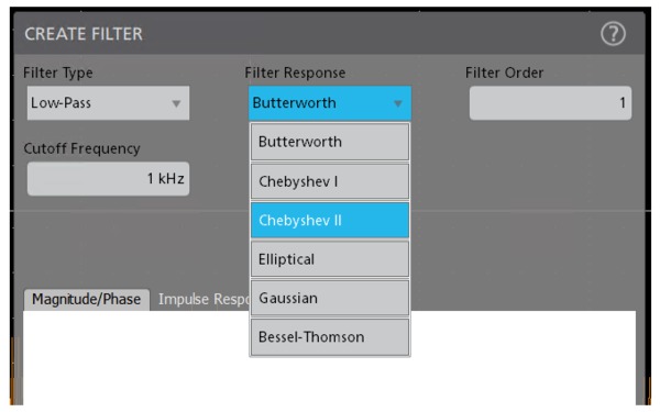
With the User defined filter tools, Tektronix provides a solution that includes the most common IIR and FIR (Gaussian Window), Custom, Raised-Cosine, and Root-Raised-Cosine filters. FIR filters include; Gaussian window filters, Hilbert, Differentiator, and All-Pass filters. IIR filters include Butterworth, Chebyshev-I, Chebyshev-II, Bessel-Thompson, and Elliptical filters.
Low-pass filter
A low-Pass filter passes all the frequencies up to the specified cutoff frequency. It rejects all the frequencies above the cutoff.

High-pass filter
A high-Pass filter passes all the frequencies above the specified cutoff frequency. It rejects all the frequencies below the cutoff.
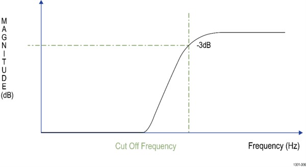
These filters are useful for eliminating DC and low-frequency components.
Band-pass filter
A Band-Pass filter passes the band of frequencies between configured lower and upper cutoff frequencies. You must specify the upper and lower cutoff frequencies.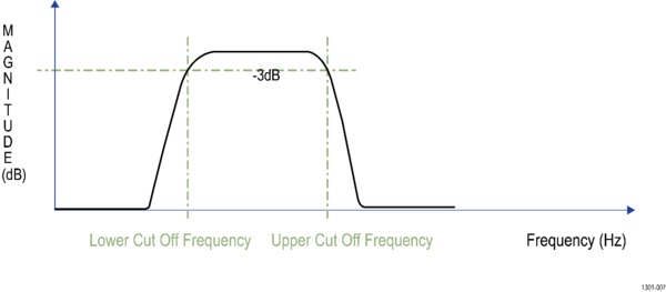
Band-stop filter
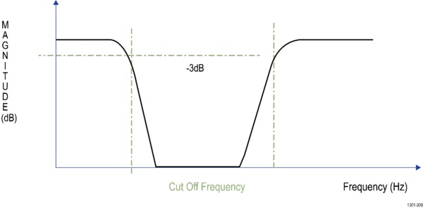
A Band-Stop filter passes all frequencies except a configured frequency band between lower and upper cutoff frequencies.
All-pass filter
The All-Pass filter has a constant amplitude or a constant gain and passes all frequencies between DC to Fs/2. You can enter a delay in seconds which introduces appropriate delay on the filtered output MATH waveform which results in a phase shift. The application computes and displays plots of magnitude and phase responses.

Bessel-Thompson filter
The Bessel-Thompson filter is optimized for better transient response with a linear phase in the pass-band.
The graph shows a low-pass response curve. This class of filters also supports high-pass, band-pass, and band-stop filters. The application computes and displays plots of magnitude, phase, impulse, and step responses.
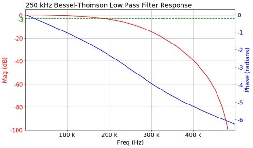
The Bessel-Thompson class of filters is commonly used as the analog bandwidth limit filter in oscilloscope channels. It is also used as the filter response type for optical reference receiver mask testing applications. The reason for its popularity is that it is the closest one can get to realizing an ideal Gaussian filter response, that is not physically realizable.
Bessel-Thomson filters are used in RF and audio applications in which the preservation of the wave shape and phase of components within a signal is important.
These filters are also used in applications where a constant group delay is critical, such as in analog video signal processing.
Gaussian window
This is an FIR filter design using the Gaussian window method. This function computes the coefficients of a finite impulse response filter. Different filter types with Gaussian window are:
- Low-pass
- High-pass
- Band-pass
- Band-stop
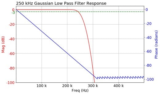
The standard deviation is a user input which defines the Gaussian window width.
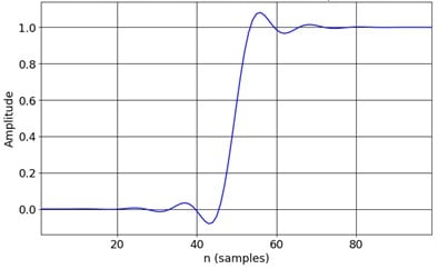
The following is an example showing low-pass FIR filter of order 100, 1.25 GS/s, 62.5 MHz cutoff frequency, and standard deviation value of 50.

Hilbert
The ideal Hilbert transform filter has a gain of one at all frequencies and shifts the phase of all frequencies by 90 degrees. This type of filter can be used to create quadrature signals over a wide frequency range.
This filter departs from its desired behavior in the frequency range of 0 to 0.025 times the sample rate and in the range of about 0.475 to 0.5 times the sample rate.
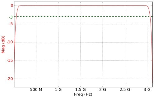
Differentiator
The ideal differentiator is a high-pass filter that shifts phase by 90 degrees. Its frequency response can be linear all the way from DC to Fs/2. The application computes and displays plots of magnitude response.
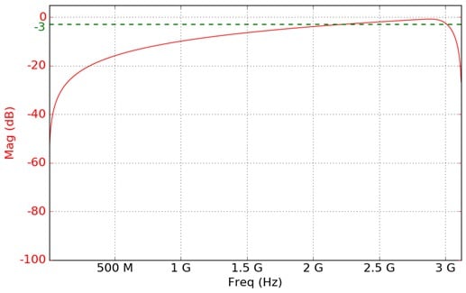
IIR filters
Butterworth filter
Butterworth filters do not have pass-band and stop-band ripple and are commonly known as "maximally flat magnitude" filters. These filters have the flattest amplitude response of all the available filters. The following graph shows an example of a low-pass response curve. This filter type also supports high-pass, band-pass and band-reject filters. The application computes and displays plots of magnitude, phase, impulse, and step responses.
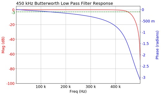
As the filter order is increased, the pass-band and stop-band performance improve, with the transition from pass-band to stop-band becoming sharper. The Butterworth method is best suited for design problems that focus on controlling pass-band and stop-band ripple.
In electrophysiology Butterworth and elliptic IIR filters are often applied. They are a good choice for DC measurement applications.
Chebyshev I
There are two types of Chebyshev filters:- Type I and Type II. Generally, Type I is referred as a regular filter, and this is the most common Chebyshev filter. The transition from pass-band to stop-band is more rapid than the Butterworth filter.
A Type I filter has equiripple in the pass-band and no-ripples in the stop-band. The UDF application provides control of pass-band ripple as part of this filter.
The following graph shows a low-pass response curve. This filter type also supports high-pass, band-pass, and band-stop filters. The application computes and displays plots of magnitude, phase, impulse, and step responses.

Chebyshev II
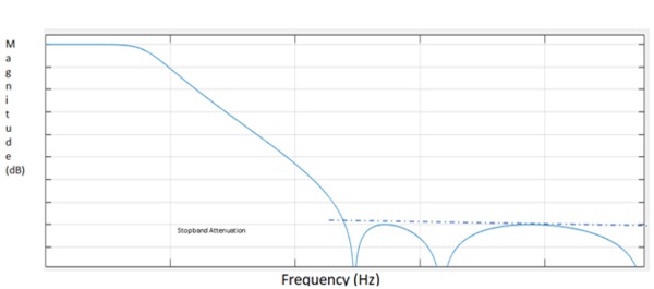
This filter is also known as the inverse Chebyshev filter. The Type II has equiripple in the stop-band and no ripples in the pass-band.
These filters have a maximally flat pass-band response. The UDF application provides control of stop-band attenuation as part of this filter.
The graph below shows a low-pass response curve. This filter type also supports high-pass, band-pass, and band-stop filters. The application computes and displays plots of magnitude, phase, impulse, and step responses.
Elliptic filter
Elliptic filters have pass-band and stop-band ripple and the sharpest roll-off near the cutoff frequency. This type of filter contains ripple behavior in both the pass-band and stop-band.
The elliptic has the fastest roll-off and lowest order filter compared to the others. The application provides control of pass-band ripple and stop-band attenuation as part of this filter.
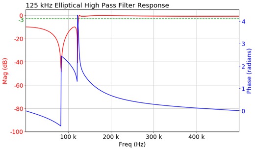
The graph shows an example of a high-pass response curve. This filter type also supports low-pass, band-pass, and band-stop filters. The application computes and displays plots of magnitude, phase, impulse, and step responses.
This filter is used in many RF and microwave applications where a very fast transition between the pass-band and stop-band frequencies is required.
Raised-Cosine (RC) and Root-Raised-Cosine (RRC) filters
Raised-Cosine and Root-Raised-Cosine filters are low-pass filters. Ideal pulse shaping filters have an infinite number of taps. The UDF tool windows the filter span based on the number of symbols.
The Symbols configuration helps in setting the window width. RC and RRC filters need several samples per symbol, hence a Symbol Duration configuration is used for this purpose.
Samples per symbol is the product of the current sample rate of oscilloscope and symbol duration. Since the sample rate is inherently a configuration of the filter, the filter response changes for different sample rates. The UDF tool designs the filter just for the current oscilloscope sample rate.
The filter order is computed as Symbols x Symbol Duration x Sample Rate. The number of taps is an odd number, to maintain an even symmetry in the impulse response.


Custom filters
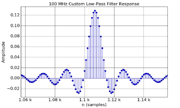
Custom filters provide the ability to design filters that require a higher ratio between Sample rate and Cutoff frequency. The custom filter order is calculated using the Remez order formula. The filter creation depends on the transition width, passband ripple, stopband attenuation, and the sample rate.
The maximum supported filter order is 15,000. The transition width and other parameters must be adjusted accordingly to get the filter order below 15,000.

Key filter parameters
A filter's response to different frequencies is characterized as pass-band, transition band, or stop-band.
Pass-band response: The filter's effect on frequency components that are passed through (mostly) unchanged.
Stop-band response: Band of highly attenuated frequencies post filtering.
Transition band: Represents frequencies in the middle, which may receive some attenuation but are not removed completely from the output signal.
Cutoff frequency: Used to specify the bandwidth of high-pass, low-pass, bandpass, and band-stop filters. The cutoff frequency is the point at which the magnitude is -3 dB from pass-band gain. This represents the 3 dB point.
3 dB point: The magnitude response shows the cutoff frequency annotation at the bottom left of the graph. This is obtained by finding the intersection of magnitude curve with -3 dB horizontal line. Sometimes cutoff frequencies are interpolated using quadratic spline interpolation to get accurate results.
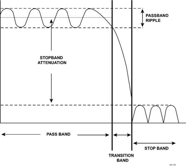
Filter roll-off rate: The slope of the transition band of a filter is referred to as its roll-off rate. This is commonly specified in dB per octave or in dB per decade.
Filter order: The order refers to the order of the filter's system function. The filter roll-off is a function of the filter order.
Impulse response: The impulse describes the transfer function of a filter in the time domain. That is, it defines the effect of a filter on the signal input resulting in a filtered output. Therefore, it is essential to understand the filter responses for good filter design. This is the output from the filter when the input is unit impulse. If an impulse is fed into a filter, its impulse response can fully define the characteristics of the filter in the time domain. Computing an FFT of the filter impulse response provides the phase and magnitude response of the filter in the frequency domain.
Step response: This response represents the integral of the impulse response for the digital filter transfer function. This is the output from the filter when the input is a unit step function.
Stop-band attenuation: Describes dB value of stop-band attenuation down from the peak pass-band value.
Pass-band ripple: Describes dB of peak-to-peak pass-band ripple in the pass-band region.
Creating the filters
To create the filters, add a new MATH. Configure the MATH source and select Math Type as Filter.
Click on Edit Filter to open the UDF tool. Configure the filter settings as per the application needs.
Clicking on the Apply Filter button on the UDF tool designs a filter response, applies the filter on the configured input source and generates a MATH filtered output with Magnitude, Phase, Impulse, and Step responses. To save the filter as .flt file, select Save Filter To File option.
Click on Generate Filter and update the filter response. This button is disabled after you generate the filter by clicking Generate Filter, until any changes are made to the configurations.
UDF tool allows you to save plot images easily. All three plots, viz. Magnitude/Phase, Impulse, and Step response can be saved at the configured location.

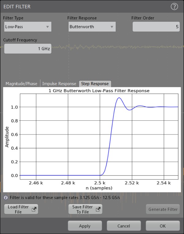
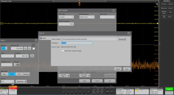
It is possible to load the previously saved filter files. To load previously saved filter, click Load Filter File button, and select any previously saved .flt file to recall any filter files.
After loading the filter file, select Apply Filter button to see the filter responses.

Filters can be saved as part of the oscilloscope session file. When saved in a session file, filter design parameters and the corresponding .flt file are also saved.
Ordering information
Models
| Product | Options | Supported instruments |
|---|---|---|
| New instrument option | 5-UDFLT | 5 Series MSO (MSO54, MSO56, MSO58) 5 Series MSO Low Profile (MSO58LP) |
| Product upgrade option | SUP5-UDFLT | |
| Floating license | SUP5-UDFLT-FL | |
| New instrument option | 6-UDFLT | 6 Series B MSO (MSO64B, MSO66B, MSO68B) 6 Series MSO (MSO64) 6 Series Low Profile Digitizer (LPD64) |
| Product upgrade option | SUP6-UDFLT | |
| Floating license | SUP6-UDFLT-FL |
Bundles
| Bundle options | Supported instruments | Description |
|---|---|---|
| 5-PRO-SIGNAL-1Y | 5 Series MSO | 1 Year Pro Signal Integrity Bundle |
| 5-ULTIMATE-1Y | 1 Year Ultimate Bundle | |
| 5-PRO-SIGNAL-PER | Perpetual License - Pro Signal Integrity Bundle | |
| 5-ULTIMATE-PER | Perpetual License - Ultimate Bundle | |
| 6-PRO-SIGNAL-1Y | 6 Series B MSO | 1 Year Pro Signal Integrity Bundle |
| 6-ULTIMATE-1Y | 1 Year Ultimate Bundle | |
| 6-PRO-SIGNAL-PER | Perpetual License - Pro Signal Integrity Bundle | |
| 6-ULTIMATE-PER | Perpetual License - Ultimate Bundle |


