
Do you want to make a quick and not-so-dirty (precise) measurement on a high-speed signal?
Don’t have time to solder a probe tip to the device?
Not sure where the source of the problem with your high-speed design is?
These are common situations that engineers often find themselves in. With time pressures increasing and an elusive problem blocking the completion of a project, you need a quick, easy, and high performance method to measure high-speed signals.
The traditional method of capturing a signal on an oscilloscope has been with a handheld scope probe. This trusty browser method of probing has several advantages, including the ability to quickly scan a series of signals by moving the probe’s tip from test point to test point. The browsing method works well if you are not worried about the fidelity of the measurement. Seeing a DC voltage level or an operating clock is sufficient. When more detailed analysis or a higher fidelity measurement is needed, many engineers choose to solder probe tips to their boards.
Now, however, with the introduction of the Tektronix P7700 probes there is a new alternative: use a precision, browser tip attached to a high bandwidth differential or TriMode™ probe. With the new high bandwidth browser tip, you’ll have the advantage of quick and easy movement of the probe from one test point to another while still maintaining measurement fidelity.
Physical challenges
But you might say, I need to probe board features and components that have very small geometries. My components are 0201 size and my differential pairs can be as close as 14 mils (0.35mm). The small size of today’s components and the density of the boards make it challenging to access test points. In addition, test points are often vias on the backside of a BGA packaged part or a decoupling capacitor located between larger parts. Board designs try to pack as much functionality on them as possible, so the via spacing is as close as the PCB design rules allow. Accessing these “via farms” are another challenge you’ll face when trying to probe a signal.


Via farm on backside of a BGA packaged component.
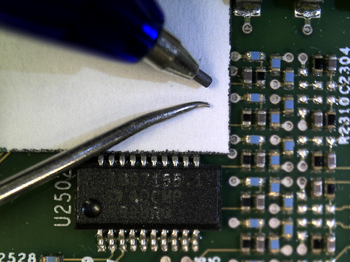
How small does the tip of a probe browser need to be in order to contact the desired test point and not any other adjacent contacts? Using an 0201 resistor as an example, the contacts on the device are 0.004” x 0.012” (0.1mm x 0.3mm), so the probe tip needs to be <1mm in diameter with contact points that are small enough to land on the components pads (~.008”/~0.2mm). If the mechanical pencil lead shown in the picture below were the probe’s tip, it would be too large to make a reliable contact. Likewise, the sharp tip of the dental pick shown in the picture is uncomfortably large to land and stick on the solder pads of the resistors.


Tip sizes compared to SMT components.
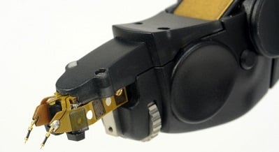
The probe tips on the Tektronix P77BRWSR shown below are less than 0.01” (0.25mm) in diameter and have 4 sharp barbs on the end of the tip that can make secure contact with SMT component pads, tightly spaced vias, and narrowly spaced differential pairs.


Tektronix P77BRWSR browser probe accessory.
Staying connected
So let’s assume that you can find a probe tip on a browser that is small and sharp, what are some of the other considerations when you decide you want to use a browser? Here are some quotes from engineers who use browsers to probe their devices. I’m sure this will sound familiar:
“When I'm browsing I can lose connections or accidentally move to other pins.”
“I want to maintain positive pressure on the tip when I'm browsing.”
Clearly, it’s important for the browser to securely attach and stay connected to the device, especially if you need to reach over to your scope while still holding the connection to your signal. Sharp points on the browser tip are helpful for this purpose. The barbs on the P77BRWSR are small and sharp enough to dig in slightly to metal contacts, such as solder or copper.


Close-up of the Tektronix P77BRWSR browser tip showing the barbs on the end of the tip.
The browser also has “pogo” pin tips that adjust to uneven surfaces and maintain contact if you relax your grip on the browser. You can see it in action in the short video clip below:
Open wide
Browsing isn’t only about narrow and small either. As one engineer told me:
“Sometimes I need a wide pitch on the browser so that I can contact a signal and a ground bus that is further away.”
Today’s high performance browsers typically allow you to adjust the tip spacing. The range of adjustment can vary, so be sure to check the minimum and maximum spacing of the tips. Maximizing the adjustment range means you can reach more signals on your devices with the browser. Tektronix’ P77BRWSR has a minimum spacing of 0 and a maximum of .21” (5.3 mm).
Note that as you adjust the spacing of the browser tips, the probe’s high frequency response changes somewhat. For maximum signal fidelity, be sure to check probe manufacturer recommendations on correcting for changes in frequency response vs. tip opening.
Test point visibility
There’s another consideration that may be obvious, but is often overlooked. Don’t make the mistake of this engineer:
“The body of the browser can get in the way visually. I have to flip it around to come in at different angles so I can see my probe points.”
Although it is not often found on a datasheet, being able to see the browser tips is a key requirement for quick and easy measurements. When evaluating high performance browsers, look for tips that reach out and away from the browser body. Check that you can clearly see the tips from as many angles as possible, so that you don’t have to twist or turn your device just to see the contacts of the probe.
The Tektronix P77BRWSR has tips that extend out from the browser body for good visibility. It also includes an LED headlight that can be turned on to improve the visibility of the probe connection point.


Tektronix P77BRWSR browser tips are easily visible from all angles.
Usability and performance
The P77BRWSR browser sets a new industry standard for usability and performance. The browser accessory works with Tektronix P7700 series TriMode probes that deliver up to 20 GHz bandwidth, minimize probe loading on the device under test and a fully de-embedded measurement based upon a full S-parameter characterization of the probe and accessories. The P77BRWSR offers high impedance (144kΩ DC resistance, 0.22pF AC loading).
Because the fidelity of a measurement depends upon the frequency response of the measurement device, the S-parameters of the accessory are stored on the browser and are uploaded to your scope when it is first attached. As the browser tip spacing changes, the frequency response is automatically adjusted based upon the width of the spacing. You don’t have to worry that your measurement is inaccurate just because you adjusted the spacing. To learn how you can start marking quick and precise browser measurements, go to: /datasheet/p7700-series-trimode%E2%84%A2-probe-family-datasheet.
Learn more about P7700 probes »
What are your experiences with using browser probes on high-speed designs? How have you overcome some of the challenges?


