Contact us
Call us at
Available 6:00 AM – 5:00 PM (PST) Business Days
Download
Download Manuals, Datasheets, Software and more:
Feedback

TBS1000C 2 Channel Digital Storage Oscilloscope
- Bandwidth 50 MHz - 200 MHz
- Analog Channels 2
- Digital Channels -
- Sample Rate 1 GS/s

TBS2000B Digital Storage Oscilloscope
- Bandwidth 70 MHz - 200 MHz
- Analog Channels 2 or 4
- Digital Channels -
- Sample Rate 1 GS/s to 2 GS/s

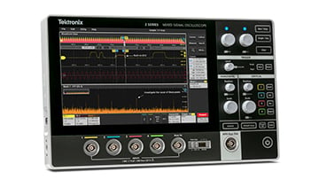
2 Series MSO Portable Mixed Signal Oscilloscope
- Bandwidth 70 MHz - 500 MHz
- Analog Channels 2 or 4
- Digital Channels 16 (optional)
- Sample Rate 1.25 GS/s - 2.5 GS/s

3 Series MDO Mixed Domain Oscilloscope
- Bandwidth 100 MHz - 1 GHz
- Analog Channels 2 or 4
- Digital Channels 16 (optional)
- Sample Rate 2.5 GS/s - 5 GS/s

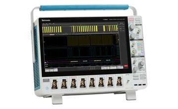
4 Series B MSO Mixed Signal Oscilloscope
- Bandwidth 200 MHz to 1.5 GHz
- Analog Channels 4 or 6
- Digital Channels Up to 48 (optional)
- Sample Rate 6.25 GS/s

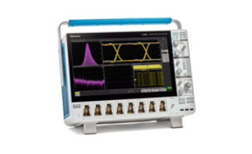
5 Series B MSO Mixed Signal Oscilloscope
- Bandwidth 350 MHz - 2 GHz
- Analog Channels 4, 6 or 8
- Digital Channels Up to 64 (optional)
- Sample Rate 6.25 GS/s

5 Series MSO Low Profile
- Bandwidth 500 MHz – 1 GHz
- Analog Channels 8
- Digital Channels Up to 64 (optional)
- Sample Rate 6.25 GS/s

6 Series B MSO Mixed Signal Oscilloscope
- Bandwidth 1 GHz - 10 GHz
- Analog Channels 4, 6 or 8
- Digital Channels Up to 64 (optional)
- Sample Rate 50 GS/s

6 Series Low Profile Digitizer
- Bandwidth 1 GHz - 8 GHz
- Analog Channels 4 (SMA)
- Digital Channels -
- Sample Rate 25 GS/s

MSO/DPO70000DX Mixed Signal/Digital Phosphor Oscilloscopes
- Bandwidth 8 GHz - 33 GHz
- Analog Channels 4
- Digital Channels 16 (optional)
- Sample Rate 25 GS/s - 100 GS/s

DPO70000SX ATI Performance Oscilloscope
- Bandwidth 13 GHz - 70 GHz
- Analog Channels 1-4
- Digital Channels -
- Sample Rate 50 GS/s - 200 GS/s

MDO3000 Mixed Domain Oscilloscope
- Bandwidth 100 MHz - 1 GHz
- Analog Channels 2 or 4
- Digital Channels 16 (optional)
- Sample Rate 2.5 GS/s - 5 GS/s

MDO4000C Mixed Domain Oscilloscope
- Bandwidth 200 MHz - 1 GHz
- Analog Channels 4
- Digital Channels 16 (optional)
- Sample Rate 2.5 GS/s - 5 GS/s
Product series comparison
 |
 |
 |
 |
 |
 |
 |
 |
 |
 |
 |
 |
 |
|
|
TBS1000C 2 Channel Digital Storage Oscilloscope
Request a Demo |
TBS2000B Digital Storage Oscilloscope
Request a Demo |
2 Series MSO Portable Mixed Signal Oscilloscope
Request a Demo |
3 Series MDO Mixed Domain Oscilloscope
Request a Demo |
4 Series B MSO Mixed Signal Oscilloscope
Request a Demo |
5 Series B MSO
Request a Demo |
5 Series MSO Low Profile
Request a Demo |
6 Series B MSO
Request a Demo |
6 Series Low Profile Digitizer
Request a Demo |
MSO/DPO70000DX Mixed Signal/Digital Phosphor Oscilloscopes
Request a Demo |
DPO70000SX ATI Performance Oscilloscope
Request a Demo |
MDO3000 Mixed Domain Oscilloscope
Request a Demo |
MDO4000C Mixed Domain Oscilloscope
Request a Demo |
|
| Bandwidth |
50 MHz - 200 MHz |
70 MHz - 200 MHz |
70 MHz - 500 MHz |
100 MHz - 1 GHz |
200 MHz to 1.5 GHz |
350 MHz - 2 GHz |
500 MHz – 1 GHz |
1 GHz - 10 GHz |
1 GHz - 8 GHz |
8 GHz - 33 GHz |
13 GHz - 70 GHz |
100 MHz - 1 GHz |
200 MHz - 1 GHz |
| Analog Channels |
2 |
2-4 |
2 or 4 |
2 or 4 |
4 or 6 |
4, 6 or 8 |
8 |
4, 6 or 8 |
4 (SMA) |
4 |
1-4 |
2 or 4 |
4 |
| Digital Channels |
- |
- |
16 (optional) |
16 (optional) |
Up to 48 (optional) |
Up to 64 (optional) |
Up to 64 (optional) |
Up to 64 (optional) |
- |
16 (optional) |
- |
16 (optional) |
16 (optional) |
| Sample Rate |
1 GS/s |
1 GS/s to 2 GS/s |
1.25 GS/s all channels; 2.5 GS/s half channels |
2.5 GS/s - 5 GS/s |
6.25 GS/s |
6.25 GS/s |
6.25 GS/s |
50 GS/s |
25 GS/s |
25 GS/s - 100 GS/s |
50 GS/s - 200 GS/s |
2.5 GS/s - 5 GS/s |
2.5 GS/s - 5 GS/s |
| Record Length |
20k points |
5 Mpoints |
10 Mpts |
10 M |
31.25 M to 62.5 M |
62.5 M - 500 M |
125 M - 500 M |
62.5 M - 1 G |
125 M - 1 G |
31.25M - 1G points |
62.5M - 1G point |
10 M |
20 M |
| Spectrum Analyzer |
Standard Math FFT |
Standard Math FFT |
Standard Math FFT |
Built-in dedicated RF path up to 3 GHz (optional) |
Spectrum View with integrated digital down converter; Each channel with 312.5 MHz span, 500M span (optional) |
Spectrum View with integrated digital down converter; Each channel with 312.5 MHz span standard, 500 MHz span (optional) |
Spectrum View with integrated digital down converter; Each channel with 312.5 MHz span standard, 500 MHz span optional Standard Math FFT |
Spectrum View with integrated digital down converter; Each channel with 1.25 GHz span standard, 2 GHz span (optional) |
Spectrum View with integrated digital down converter; Each channel with 1.25 GHz span standard, 2 GHz span optional |
Standard Math FFT |
Standard Math FFT |
Built-in dedicated RF path up to 3 GHz |
Built-in dedicated RF path up to 6 GHz |
| Function Generator Output |
- |
- |
1 (optional, multiplexed with Aux Out) |
1 (optional) |
1 (optional) |
1 (optional) |
1 (optional) |
1 (optional) |
1 (optional) |
- |
- |
1 (optional) |
1 (optional) |
| Maximum Waveform Capture Rate |
- |
10,000 times per second |
- |
>280,000 wfm/s |
> 500,000 wfms/s |
>500,000 wfms/s |
>500,000 wfms/s |
>500,000 (Peak Detect, Envelope acquisition mode), |
>500,000 (Peak Detect, Envelope acquisition mode) |
>300,000 wfms/s |
>300,000 wfms/s |
>235,000 - >280,000 wfm/s |
>270,000 - >340,000 wfm/s |
| RF Channels |
- |
- |
- |
1 (optional) |
- |
- |
- |
- |
- |
- |
- |
1 |
1 |
| RF Frequency Range |
- |
- |
- |
9 kHz to 1 GHz or 3 GHz (optional) |
Spectrum View DC to bandwidth of scope (-3dB) |
Spectrum View DC to bandwidth of scope (-3dB) |
Spectrum View DC to bandwidth of scope (-3dB) |
Spectrum View DC to bandwidth of scope (-3dB) |
Spectrum View DC to bandwidth of scope (-3dB) |
- |
- |
9 kHz - 1 GHz |
9 kHz – 3 GHz/ 6 GHz (optional) |
| Trigger Types |
Edge, Pulse Width, Runt, Line |
Edge, Pulse Width, Runt |
Edge, Pulse Width, Timeout, Runt, Logic, Setup/Hold, Rise/Fall, Parallel, Serial Bus (optional) |
Edge |
Edge |
Edge |
Edge |
Edge |
Edge |
Comm, Bus, I2C, SPI, CAN, LIN, Flexray, RS-232/422/485/UART, USB, Edge, B Event Scan, Glitch, Pattern, Runt, Serial Pattern, Setup/Hold, State, Timeout, Transition, Visual, Width, Window |
Edge, B Event Scan, Glitch, Pattern, Runt, Setup/Hold, State, Timeout, Transition, Visual, Width, Window |
Edge |
Edge |
| Optional Analysis |
- |
- |
I2C, SPI, RS-232/422/485/UART, CAN, CAN FD, LIN, SENT decode |
I²C/SPI decode |
1-Wire decode |
1-Wire decode |
1-Wire decode |
1-Wire decode |
1-Wire decode |
MIPI® D-PHY Testing (D-PHY), DDR Memory Bus Analysis (DDRA), DPOJET Jitter And Eye Diagram Analysis (DJA), DisplayPort 1.2 Source Test Automation (DP12), Ethernet Compliance Test Solution (ET3), HDMI Compliance Test Solution (HT3), HSIC Electrical Validation and Protocol Decode (HSIC), MHL Advanced Analysis and Compliance Test (MHD), MOST Electrical Compliance and Debug (MOST), MIPI M-PHY Transmitter Debug, Characterization and Compliance Test (M-PHY), PCI Express Transmitter Compliance and Debug (PCE3), SAS 12 Gb/s Test (SAS3), Serial Data Link Analysis Solution Software (SLE, SLA), SFP+ Compliance and Debug (SFP-TX), SignalVu Vector Signal Analysis Software (SVE), Thunderbolt TX Compliance Test (TBT-TX), USB 2.0 Compliance Test Solution (USB), USB 3.0 Transmitter Test (USB3) |
DPOJET Jitter and Eye Diagram Analysis (DJA), Serial Data Link Analysis Visualizer (SDLA64), SignalVu Vector Signal Analysis (SVE) |
CAN/LIN decode |
CAN/LIN decode |
| Vertical Accuracy |
- |
3% |
±2.0% |
±1.5% |
±1% |
±1% |
±1% |
±1% |
50 Ω: ±1.0% of full scale, (±2.0% of full scale at 1mV/div) |
±2% |
±2% |
±1.5% |
±1.5% |
| Automated Measurements |
32 |
32 and FFT function for thorough waveform analysis |
36 |
- |
- |
- |
- |
- |
- |
53 |
53 |
- |
- |
| No. Of Application Modules Range |
- |
- |
- |
- |
- |
- |
- |
- |
- |
- |
- |
- |
- |
| Rise Time |
7.0 ns - 2.1 ns |
3.5ns~5ns |
5 ns to 950 ps (70MHz to 500MHz) |
4000 ps to 400 ps (100 MHz to 1 GHz) |
2.3 ns to 450 ps (200 MHz to 1.5 GHz) |
175 ps - 1 ns |
350 ps |
400 ps - 40 ps (1 GHz - 10 GHz) |
400 ps - 50 ps (1 GHz - 8 GHz) |
9 ps - 98 ps |
<6ps - 13ps |
400 ps - 4 ns |
175 ps - 3.5 ns |
| Display |
7-inch(178mm) WVGA color display |
9 inch TFT WVGA |
10.1 inches, 1280 x 800 |
11.6 inches, 1920 x 1080 HD |
13.3 in, 1920x1080 HD |
15.6 in, 1920x1080 HD |
- |
15.6 in, 1920x1080 HD |
- |
12.1 in (308 mm), Color |
6.5 in (165 mm), Color |
9 in. (229 mm), Color |
10.4 in. (264 mm), Color |
| Warranty |
5-year Warranty |
5 years |
1 year |
3 years |
1 years |
1 year |
3 years |
1 year |
1 year |
One-year Warranty |
One-year Warranty |
3 years |
3 years |
| SA Real Time Capture Bandwidth |
- |
- |
- |
1 GHz (optional), 3 GHz (optional) |
Spectrum View: 312.5 MHz, 500 MHz (optional) |
Spectrum View: 312.5 MHz, 500 MHz (optional) |
Spectrum View: 312.5 MHz, 500 MHz (optional) |
Spectrum View: 1.25 GHz, 2 GHz (optional) |
Spectrum View: 1.25 GHz, 2 GHz (optional) |
- |
- |
Up to 3 GHz |
Up to 3.75 GHz |
| Base Price | US $459 | US $1,670 | US $1,940 | US $4,690 | US $9,180 | US $21,300 | Contact Us | US $39,400 | Contact Us | Contact Us | Contact Us | US $7,560 | US $11,600 |
Oscilloscope Probes and Accessories
Choose from a broad portfolio of Tektronix probes and accessories, all perfectly matched to our industry-leading oscilloscopes. With over 100 choices available, select the oscilloscope probe you need for your specific testing application.
Current Probes
Best-in-class bandwidth and sensitivity. Safety Certified.

Low Voltage Differential Probes
Signal fidelity for serial bus PHY measurements.

High Voltage Differential Probes
Industry leading performance up to 6000V. Safety Certified.

IsoVu Isolated Probes
Probing systems make high-resolution measurements in the presence of common mode signals or noise.

Passive Probes
Highest bandwidth, lowest probe loading.

Power Rail Probes
Power rail probes offer low noise, low loading, high bandwidth, and high DC offset specifically for power integrity measurements.
Software for your Oscilloscope
Analyze your most challenging system designs by adding one of our oscilloscope software packages to your scope.
TekScope™ oscilloscope software
Analyze waveforms anytime from anywhere by turning your PC into an oscilloscope with TekScope.

Keithley KickStart Software
Start measuring in minutes without complex programming. Perform I-V characterization and more.
Oscilloscope applications

Oscilloscope Learning Center
Learn how to use oscopes, spectrum analyzers, source measure units, and other instruments to troubleshoot system anomalies, provide measurement insights, debug EMI, and more.Primer
Oscilloscope Basics and Fundamentals
In this comprehensive primer, you can learn everything you need to know about oscilloscope fundamentals, types, systems, setup, and use.
SOLUTION BRIEF
Capacitance and Inductance Measurements Using an Oscilloscope and a Function Generator
Learn about impedance, impedance measurement methods, measurement ranges, and more with real-world examples.
APPLICATION NOTE
Spectrum View: A New Approach to Frequency Domain Analysis on Oscilloscopes
Learn about how Spectrum View analysis allows optimization of both time domain and frequency domain displays independently to offer important insights.
APPLICATION NOTE
How Oscilloscope Probes Affect Your Measurement
Learn how an oscilloscope probe changes the signal you’re measuring at the test point and what probing specifications to look for to minimize probing effects.
Oscilloscope FAQs
What is an oscilloscope?
An oscilloscope, formerly known as an oscillograph (informally scope, oscope, or O-scope), graphically displays electrical signals and shows how they change over time. Learn more about how an oscilloscope works, what they're used for and the types of oscilloscopes.
What is an oscilloscope used for?
Engineers use an oscilloscope (also referred to informally as an oscope) to design, manufacture or repair electronic equipment to verify that a device is working properly.
How does an oscilloscope work?
An oscilloscope reconstructs electrical signals using three systems—vertical, horizontal and trigger—which work together to gather information about the electrical signal, so the oscilloscope can graphically display those signals.
How does an oscilloscope measure voltage?
An oscilloscope measures voltage waves by capturing physical phenomena such as vibrations or temperature, or electrical phenomena such as current or power with a sensor. The oscilloscope then converts that signal into a waveform and graphically displays it where the horizontal axis represents time and the vertical axis represents voltage.
What does an oscilloscope measure?
An oscilloscope measures voltage waves, but it can also be used to measure current, resistance, sound, capacitance, frequency and more.
How does an oscilloscope measure frequency?
Most oscilloscopes measure frequency automatically, but you can also use a simple equation (frequency=1/period) and the horizontal scale on your oscilloscope to measure frequency manually.
How can an oscilloscope measure current?
You can use an oscilloscope to measure current by measuring the voltage dropped across a shunt resistor or by using a current probe.
What are the different types of oscilloscopes?
There are two main types of oscilloscopes: analog and digital. Most engineers today use digital oscilloscopes, which fall into five categories: digital storage oscilloscopes, digital phosphor oscilloscopes, mixed signal oscilloscopes, mixed domain oscilloscopes, and digital sampling oscilloscopes.
What is a mixed signal oscilloscope?
A mixed signal oscilloscope is a type of digital storage oscilloscope designed to capture, display, and compare both analog and digital signals.
What is a mixed domain oscilloscope?
Like a mixed signal oscilloscope, a mixed domain oscilloscope measures analog and digital signals, but has built-in spectrum analyzer, allowing engineers to make radio frequency (RF) measurements as well.
How to use an oscilloscope?
Learn the basics of how to set up and how to use an oscilloscope as well as basic measurement techniques with our Oscilloscope How-To Guide.
How to choose an oscilloscope?
There are many factors to consider when buying an oscilloscope. Learn more in our guide on how to choose the best oscilloscope for your application.
How much does an oscilloscope cost?
Oscilloscope pricing can range greatly depending on whether you’re a hobbyist looking for a simple setup or an electrical engineer using an oscilloscope in a lab setting. How you choose to configure your oscilloscope, its bandwidth and the number of channels are big factors in determining oscilloscope price. Tektronix oscilloscopes, for example, can range from around $500 to tens of thousands of dollars for more sophisticated instruments and advanced configurations. For guidance on finding the oscilloscope that best meets your needs, contact the experts at Tektronix.

"We couldn't find equipment capable of making measurements such as the high-side gate-source voltage. In fact, most differential signals in the presence of today’s higher frequency common mode
voltages cannot be measured accurately. That’s when Tektronix stepped in.”


